EP0317146A2 - Trommelantriebsvorrichtung zur Verwendung in einem Spielautomaten - Google Patents
Trommelantriebsvorrichtung zur Verwendung in einem Spielautomaten Download PDFInfo
- Publication number
- EP0317146A2 EP0317146A2 EP88310452A EP88310452A EP0317146A2 EP 0317146 A2 EP0317146 A2 EP 0317146A2 EP 88310452 A EP88310452 A EP 88310452A EP 88310452 A EP88310452 A EP 88310452A EP 0317146 A2 EP0317146 A2 EP 0317146A2
- Authority
- EP
- European Patent Office
- Prior art keywords
- reel
- driving device
- members
- impact mitigating
- reel driving
- Prior art date
- Legal status (The legal status is an assumption and is not a legal conclusion. Google has not performed a legal analysis and makes no representation as to the accuracy of the status listed.)
- Granted
Links
Images


Classifications
-
- G—PHYSICS
- G07—CHECKING-DEVICES
- G07F—COIN-FREED OR LIKE APPARATUS
- G07F17/00—Coin-freed apparatus for hiring articles; Coin-freed facilities or services
- G07F17/32—Coin-freed apparatus for hiring articles; Coin-freed facilities or services for games, toys, sports, or amusements
- G07F17/3202—Hardware aspects of a gaming system, e.g. components, construction, architecture thereof
- G07F17/3204—Player-machine interfaces
- G07F17/3211—Display means
- G07F17/3213—Details of moving display elements, e.g. spinning reels, tumbling members
-
- Y—GENERAL TAGGING OF NEW TECHNOLOGICAL DEVELOPMENTS; GENERAL TAGGING OF CROSS-SECTIONAL TECHNOLOGIES SPANNING OVER SEVERAL SECTIONS OF THE IPC; TECHNICAL SUBJECTS COVERED BY FORMER USPC CROSS-REFERENCE ART COLLECTIONS [XRACs] AND DIGESTS
- Y10—TECHNICAL SUBJECTS COVERED BY FORMER USPC
- Y10T—TECHNICAL SUBJECTS COVERED BY FORMER US CLASSIFICATION
- Y10T403/00—Joints and connections
- Y10T403/45—Flexibly connected rigid members
- Y10T403/454—Connecting pin traverses radially interposed elastomer
Definitions
- This invention relates to a reel driving device for use in the slot machine in which a reel is driven by a pulse motor or the like.
- reels are started to rotate by a rotating force caused by an impact force mechanically given by a lever operation and is caused to stop rotating by locking a paw preset for each symbol of each reel by pushing, e.g. a stop button.
- a combination of symbols the symbols of each reel has different signal grooves, and when the reels are stopped, a combination of symbols are judged based on their signal grooves.
- a signal for actuating the pulse motors of respective reels is generated by a lever operation to cause the pulse motors to rotate the reels, and the reels are stopped based on a signal for stopping the respective pulse motors generated by pushing a stop button.
- Symbols of the respective reels are judged by counting driving pulses supplied to the respective pulse motors and judging a combination of the counted signals by a microcomputer (Japanese Utility Model Publication No. 7268/1988, Japanese Utility Model Laid Open Publication No. 115566/1982 and U.S. Patent No. 4410178).
- the pulse motor which has a small torque with respect to a load of the reel accelerates the rotation of the reel considerably so lower compared with the mechanical drive that the rotation of the reel is not regular (awkward) and has low acceleration. That is, this results in a problem of poorer images compared with the mechanically driven slot machine.
- this invention aims at providing a reel driving device for use in the slot machine for driving a reel by a pulse motor which absorbs to mitigate the inertia force of the reel by an elastic member, whereby the reel is driven at high acceleration and regularly, and less deviates even when the reel is abruptly stopped.
- This invention comprises a drive disk, a reel and reel fixing means.
- the drive disk has a drive shaft fixing boss for prohibiting the drive shaft from idling, and impact mitigating bosses for mitigating an impact force exerted by the motor, provided therein opposed to each other with respect to the drive shaft fixing boss.
- the reel has holes for receiving the drive shaft fixing boss and the impact mitigating bosses provided at corresponding positions thereof.
- the reel fixing means prohibit the reel from moving along the drive shaft.
- the inertia force of the reel generated in its operation is absorbed by the interaction among the drive disk having the drive shaft fixing boss and the impact mitigating bosses, the reel, and the reel fixing means. Consequently the inertia force of the reel generated in an operation of the reel is absorbed, and the reel less deviates when suddenly stopped.
- FIG. 1 is a broken perspective view including the reel driving device for use in the slot machine according to the embodiment of this invention.
- a drive shaft 1 of a motor has a flat surface (A) formed axially on the end portion thereof and a circumferential groove (B) formed in the tip of the end portion. Accordingly the section of the drive shaft of the motor contains a chord and an arc.
- This embodiment basically comprises a drive disk 2, reel 3 and reel fixing means. Each element will be explained one by one.
- a drive disk 2 there are provided a drive shaft fixing boss 2a which receives the drive shaft 1 of the motor, and impact mitigating bosses 2b,2b which mitigate the impact force generated when the motor is actuated and is suddenly stopped.
- the shaft fixing boss 2a is constructed so as to receive the drive shaft 1 of the motor and enables the drive shaft 1 to transmit the drive force of the motor to a reel disk without idling in the boss.
- the impact mitigating bosses 2b,2b are arranged symmetrically to the drive shaft fixing boss, and each comprises a cylindrical member 2b1 and an O ring 2c of, e.g., rubber, put around the cylindrical member.
- the two cylindrical members 2b1 are arranged symmetrically and two O rings 2c are put around each cylindrical member 2b1.
- the number of the cylindrical members 2b1, the distance between the drive shaft fixing boss and the respective impact mitigating bosses, and the number of the O ring are variable depending on a generated impact force.
- the shape of the impact mitigating bosses is not limited to a cylinder but may be, e.g., a polygonal cone or elliptical cone.
- each impact mitigating bosses are elliptical cone
- the bosses are so arranged that their major axes are laid in the radial direction. This arrangement is effective to absorb the impact force.
- the impact mitigating bosses per se may be made of an elastic material.
- a reel 3 has a first boss hole 3a for receiving the drive shaft fixing boss 2a, and second boss holes 3b,3b for receiving the impact mitigating bosses 2b,2b formed therein so as to receive the drive force from the drive disk 2.
- the first boss hole 3a is for aligning the drive shaft 1 of the motor and the rotary shaft of the reel 3.
- the second boss holes 3b,3b are for transmitting the drive force to the reel 3 and mitigating the impact force. Accordingly, it is preferable that the impact mitigating bosses 2b are inserted in the second boss holes 3b,3b without plays therein.
- the inner diameter of the second boss holes 3b is made a little smaller that of the outer diameter of the cylindrical members 2b1 with the O rings 2c, and the impact mitigating bosses 2b are inserted in the second boss holes 3b, deforming the O rings 2c.
- reinforcing ribs 3c,3c for reinforcing the reel 3 may be provided at an interval which allows the O rings 2c,2c to be held by the reinforcing ribs 3c,3c.
- the extra second boss holes 3b,3b do not have to be provided, which can simplify the fabrication of the reel 3 and improve the strength of the reel 3.
- the reel fixing means comprise a washer 4 and E ring 5.
- the washer 4 of which the outer diameter is bigger than the inner diameter of the first boss hole 3a at least, and of which the inner diameter is bigger than the outer diameter of the drive shaft 1, is used.
- the reel 3 is assembled by mounting the drive disk 2 on the drive shaft 1, then inserting the drive shaft fixing boss 2a and the impact mitigating bosses 2b,2b, of the drive disk 2 in the first boss hole 3a and the second boss holes 3b,3b, of the reel 3, and inserting the drive shaft 1 into a washer 4. Finally an E ring 5 is engaged in the groove in the drive shaft 1 so as to prohibit the axial displacement of the reel 3.
- the circumferential displacement of the reel 3 is prohibited by the drive shaft 1 being inserted in the drive shaft fixing boss 2a, and the axial displacement of the reel 3 is prohibited by the drive shaft 1 being inserted in the washer 4.
- the drive force of the motor is transmitted from the drive shaft 1 to the drive shaft fixing boss 2a of the drive disk 2 and is transmitted from the impact mitigating bosses 2b,2b to the second boss holes 3b,3b of the reel 3. Accordingly, an impact force generated when the motor is driven elastically deforms the O rings 2c put around the cylindrical members 2b1 provided in the drive disk 2, so that an inertia force of the reel 3 generated when the reel 3 is actuated is absorbed. An impact force generated when the motor is abruptly stopped is transmitted to the O rings 2c and deforms the O rings 2c, so that the deviation of the reel 3 is lessened when the reel 3 is stopped.
- Fig. 2 is a broken perspective view including the reel driving device for use in the slot machine according to another embodiment of this invention.
- This embodiment basically comprises a drive disk 2, a reel 3 and reel fixing means.
- the embodiment differs from the embodiment of Fig. 1 in that each impact mitigating bosses 2b comprises a conical member 2b2,2b2 tapered toward the tip thereof.
- the shape and position of the conical members 2b2,2b2 are variable, depending on an impact force resulting from the inertia force of the reel 3.
- two conical members 2b2,2b2 are provided equidistantly from the respective cylindrical members 2b1,2b1.
- the second boss holes 3b,3b which receive the conical members 2b2,2b2 are so arranged that only the tip portions of the conical members 2b2,2b2 are received therein. Accordingly the flexibility of the constituent members can be fully exerted.
- both the cylindrical members 2b1,2b1, and the conical members 2b2,2b2 are used, but the conical members 2b2,2b2 alone may be used.
- the other constituent members and their operation are the same as in the former embodiment, and their description is omitted.
- the shape of the forward end portion of the drive shaft 1 of the motor is not limited to the shape of the embodiments (comprising an arc and a chord) but may be polygon, such as square, hexagon or others, or ellipse.
- the number and the pitch of the impact mitigating bosses 2b provided in the drive disk 2, and the distance between the center of the drive disk and the respective impact mitigating bosses 2b are variable, depending on an impact force to be mitigated. Generally a suitable value is determined, based on experimental and empirical data.
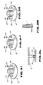
- Fig.3 shows modifications of a reel driving device for use in the slot machine according to this invention.
- Fig.3A is a perspective view of the first modification of a drive disk composing the reel driving device.
- the impact mitigating bosses comprise elastic ring members. and polygonal sectional members inserted in the elastic ring members.
- Fig. 3B is a perspective view of the second modification of the drive disk.
- the difference from the first modification is that the impact mitigating bosses comprise elastic ring members, and elliptical sectional cylindrical members inserted in the elastic ring members.
- Fig.3C is a perspective view of the third modification of the drive disk.
- the difference from the first modification (see Fig.3A) is that the impact mitigating bosses comprise elastic cylindrical members.
- Fig.3D is a perspective view of the fourth modification of the drive disk.
- the difference from the third modification is that the impact mitigating bosses comprise polygonal sectional elastic members.
- Fig.3E is a perspective view of the fifth modification of the drive disk.
- the difference from the fourth modification is that the impact mitigating bosses comprise elliptical sectional cylindrical elastic members.
- Fig. 3F is a perspective view of the sixth modification of the drive disk.
- the difference from the embodiment (see Fig.1) is that the impact mitigating bosses comprise conical members.
- Fig. 3G is a perspective view of the seventh modification of the drive disk.
- the difference from the sixth modification is that the impact mitigating bosses comprise polygonal conical members.
- Fig.3H is a perspective view of the eighth modification of the drive disk.
- the difference from the seventh modification (see Fig.3G) is that the impact mitigating bosses comprise elliptical conical members.
- Fig.3I is a perspective view of the ninth modification of the drive disk.
- the difference from the embodiment described above (see Fig.1) is that the impact mitigating bosses comprise elastio ring members, and conical members inserted in the elastic ring members.
- Fig.3J is a perspective view of the tenth modification of the drive disk.
- the difference from the ninth modification is that the impact mitigating bosses comprise elastic ring members, and polygonal conical members inserted in the elastic ring members.
- Fig. 3K is a perspective view of the eleventh modification of the drive disk.
- the difference from the tenth modification is that the impact mitigation bosses comprise elastic ring members, and elliptical conical members inserted in the elastic ring memebers.
- Fig.3L is a sectional view of the modification of a reel composing the reel driving device.
- the difference from the embodiment described above (see Fig.1) is that the reel has impact mitigating boss holes having a little smaller inner diameter than the outer diameter of tbe elastic ring member in its inserted state.
- Fig.3M is a perspective view of the modification of reel fixing means composing the reel driving device.
- the reel fixing means comprise a pin placed through the drive shaft.
Landscapes
- Physics & Mathematics (AREA)
- General Physics & Mathematics (AREA)
- Slot Machines And Peripheral Devices (AREA)
- Portable Nailing Machines And Staplers (AREA)
- Pinball Game Machines (AREA)
- Display Devices Of Pinball Game Machines (AREA)
- Coin-Freed Apparatuses For Hiring Articles (AREA)
- Connection Of Motors, Electrical Generators, Mechanical Devices, And The Like (AREA)
Priority Applications (1)
| Application Number | Priority Date | Filing Date | Title |
|---|---|---|---|
| AT88310452T ATE95622T1 (de) | 1987-11-13 | 1988-11-07 | Trommelantriebsvorrichtung zur verwendung in einem spielautomaten. |
Applications Claiming Priority (2)
| Application Number | Priority Date | Filing Date | Title |
|---|---|---|---|
| JP287928/87 | 1987-11-13 | ||
| JP62287928A JP2666936B2 (ja) | 1987-11-13 | 1987-11-13 | スロットマシンのリール駆動装置 |
Publications (3)
| Publication Number | Publication Date |
|---|---|
| EP0317146A2 true EP0317146A2 (de) | 1989-05-24 |
| EP0317146A3 EP0317146A3 (en) | 1989-11-08 |
| EP0317146B1 EP0317146B1 (de) | 1993-10-06 |
Family
ID=17723545
Family Applications (1)
| Application Number | Title | Priority Date | Filing Date |
|---|---|---|---|
| EP88310452A Expired - Lifetime EP0317146B1 (de) | 1987-11-13 | 1988-11-07 | Trommelantriebsvorrichtung zur Verwendung in einem Spielautomaten |
Country Status (10)
| Country | Link |
|---|---|
| US (1) | US4928964A (de) |
| EP (1) | EP0317146B1 (de) |
| JP (1) | JP2666936B2 (de) |
| AT (1) | ATE95622T1 (de) |
| AU (1) | AU612423B2 (de) |
| DE (1) | DE3884759T2 (de) |
| ES (1) | ES2047037T3 (de) |
| GB (1) | GB2212246B (de) |
| MY (1) | MY103460A (de) |
| NZ (1) | NZ226931A (de) |
Cited By (4)
| Publication number | Priority date | Publication date | Assignee | Title |
|---|---|---|---|---|
| DE4402109A1 (de) * | 1994-01-26 | 1995-07-27 | Nsm Ag | Antriebsvorrichtung für einen Umlaufkörper eines Unterhaltungsgerätes |
| AU679555B2 (en) * | 1993-08-04 | 1997-07-03 | Pfizer Inc. | Antiparasitic agents based on avermectin substituted in the 5-position by alkylidene |
| ES2176113A1 (es) * | 2001-02-14 | 2002-11-16 | Gaming Technology Distrib S L | Rodillo para maquinas recreativas con almohadilla amortiguadora. |
| EP1475759A1 (de) * | 2003-05-09 | 2004-11-10 | Aruze Corporation | Regelungsvorrichtung zum Anhalten eines Motors |
Families Citing this family (9)
| Publication number | Priority date | Publication date | Assignee | Title |
|---|---|---|---|---|
| JP4652910B2 (ja) * | 2005-07-01 | 2011-03-16 | 株式会社大都技研 | 遊技台の可変表示装置 |
| JP2007325637A (ja) * | 2006-06-06 | 2007-12-20 | Daito Giken:Kk | 遊技台 |
| JP4755541B2 (ja) * | 2006-06-29 | 2011-08-24 | 株式会社大都技研 | 遊技台の可変表示装置 |
| US7624985B2 (en) * | 2006-12-05 | 2009-12-01 | Konami Gaming Incorporated | Reel assembly and gaming machine comprising the same |
| JP5402302B2 (ja) * | 2009-06-24 | 2014-01-29 | 株式会社三洋物産 | 遊技機 |
| JP5397685B2 (ja) * | 2009-10-07 | 2014-01-22 | 株式会社三洋物産 | 遊技機 |
| JP6501290B2 (ja) * | 2014-09-29 | 2019-04-17 | Necエンベデッドプロダクツ株式会社 | リール回転機構 |
| JP6881835B2 (ja) * | 2016-09-30 | 2021-06-02 | Necエンベデッドプロダクツ株式会社 | 回転装置、遊技機、および回転方法 |
| US20220157124A1 (en) * | 2019-03-25 | 2022-05-19 | Sammy Corporation | Gaming machine |
Family Cites Families (16)
| Publication number | Priority date | Publication date | Assignee | Title |
|---|---|---|---|---|
| US1763841A (en) * | 1928-12-21 | 1930-06-17 | Burns S Watling | Display apparatus |
| US2565606A (en) * | 1946-10-09 | 1951-08-28 | Guy & Murton Inc | Universal joint |
| GB1255701A (en) * | 1969-01-01 | 1971-12-01 | Tmm Research Ltd | Improvements in roll driving arrangements |
| GB1423415A (en) * | 1972-07-05 | 1976-02-04 | New Century Novelty Co Pty | Position sensing device for a movable member |
| DE2838339C3 (de) * | 1978-09-02 | 1981-10-08 | Nsm-Apparatebau Gmbh & Co Kg, 6530 Bingen | Münzbetätigtes Spielgerät |
| JPS57115566A (en) * | 1981-01-08 | 1982-07-19 | Canon Inc | Recorder |
| JPS6325887Y2 (de) * | 1981-01-12 | 1988-07-14 | ||
| JPS6138633Y2 (de) * | 1981-04-24 | 1986-11-07 | ||
| US4410178A (en) * | 1981-05-21 | 1983-10-18 | Starpoint Electrics Limited | Gaming machines |
| GB2126690B (en) * | 1982-09-07 | 1986-01-08 | Koppers Co Inc | Flexible coupling |
| JPS6083679U (ja) * | 1983-11-14 | 1985-06-10 | 株式会社ユニバーサル | スロツトマシン用リ−ル |
| JPH0337651Y2 (de) * | 1985-05-16 | 1991-08-08 | ||
| SU1323780A1 (ru) * | 1985-08-07 | 1987-07-15 | Симферопольский Филиал Научно-Производственного Объединения "Агроприбор" | Втулочно-пальцева муфта |
| JPS6290685U (de) * | 1985-11-27 | 1987-06-10 | ||
| JPS637268A (ja) * | 1986-06-25 | 1988-01-13 | Inoue Japax Res Inc | 研削装置 |
| JPH051643Y2 (de) * | 1986-06-30 | 1993-01-18 |
-
1987
- 1987-11-13 JP JP62287928A patent/JP2666936B2/ja not_active Expired - Fee Related
-
1988
- 1988-11-01 US US07/265,711 patent/US4928964A/en not_active Expired - Lifetime
- 1988-11-04 AU AU24739/88A patent/AU612423B2/en not_active Expired
- 1988-11-05 MY MYPI88001270A patent/MY103460A/en unknown
- 1988-11-07 ES ES88310452T patent/ES2047037T3/es not_active Expired - Lifetime
- 1988-11-07 GB GB8826036A patent/GB2212246B/en not_active Expired - Lifetime
- 1988-11-07 AT AT88310452T patent/ATE95622T1/de not_active IP Right Cessation
- 1988-11-07 EP EP88310452A patent/EP0317146B1/de not_active Expired - Lifetime
- 1988-11-07 DE DE88310452T patent/DE3884759T2/de not_active Expired - Lifetime
- 1988-11-11 NZ NZ226931A patent/NZ226931A/en unknown
Cited By (7)
| Publication number | Priority date | Publication date | Assignee | Title |
|---|---|---|---|---|
| AU679555B2 (en) * | 1993-08-04 | 1997-07-03 | Pfizer Inc. | Antiparasitic agents based on avermectin substituted in the 5-position by alkylidene |
| DE4402109A1 (de) * | 1994-01-26 | 1995-07-27 | Nsm Ag | Antriebsvorrichtung für einen Umlaufkörper eines Unterhaltungsgerätes |
| ES2176113A1 (es) * | 2001-02-14 | 2002-11-16 | Gaming Technology Distrib S L | Rodillo para maquinas recreativas con almohadilla amortiguadora. |
| EP1475759A1 (de) * | 2003-05-09 | 2004-11-10 | Aruze Corporation | Regelungsvorrichtung zum Anhalten eines Motors |
| US6998805B2 (en) | 2003-05-09 | 2006-02-14 | Aruze Corp. | Motor stop control device |
| US7038411B2 (en) | 2003-05-09 | 2006-05-02 | Aruze Corp. | Motor stop control device utilizable for reel-type gaming machine |
| CN100448157C (zh) * | 2003-05-09 | 2008-12-31 | 阿鲁策株式会社 | 电动机止转控制装置 |
Also Published As
| Publication number | Publication date |
|---|---|
| GB2212246A (en) | 1989-07-19 |
| ES2047037T3 (es) | 1994-02-16 |
| NZ226931A (en) | 1991-03-26 |
| DE3884759D1 (de) | 1993-11-11 |
| EP0317146A3 (en) | 1989-11-08 |
| AU2473988A (en) | 1989-05-18 |
| GB8826036D0 (en) | 1988-12-14 |
| GB2212246B (en) | 1992-06-03 |
| EP0317146B1 (de) | 1993-10-06 |
| ATE95622T1 (de) | 1993-10-15 |
| US4928964A (en) | 1990-05-29 |
| DE3884759T2 (de) | 1994-01-27 |
| JP2666936B2 (ja) | 1997-10-22 |
| MY103460A (en) | 1993-06-30 |
| AU612423B2 (en) | 1991-07-11 |
| JPH01129865A (ja) | 1989-05-23 |
Similar Documents
| Publication | Publication Date | Title |
|---|---|---|
| EP0317146A2 (de) | Trommelantriebsvorrichtung zur Verwendung in einem Spielautomaten | |
| JP4838164B2 (ja) | 動力伝達装置 | |
| DE69201805T2 (de) | Freilaufkupplung. | |
| US4603606A (en) | Unidirectional drive tool cartridge and method of manufacture | |
| JP2008241044A (ja) | ラチェットワンウェイクラッチ組立体 | |
| DE69800231T2 (de) | Leistungsübertragungsmechanismus | |
| EP2136456B1 (de) | Bausatz-Servomotor | |
| US4878880A (en) | Clutch apparatus | |
| EP0360400A2 (de) | Spulenhalter | |
| DE102020116430A1 (de) | Kraftwerkzeug | |
| US4611499A (en) | Engine starter gearing | |
| US3024630A (en) | Clutches | |
| EP0961046B1 (de) | Antriebsvorrichtung für ein Stellglied | |
| GB2297513A (en) | Hand-held power tool with removable tool holder | |
| JPH0737817B2 (ja) | 回転方向によって異なるトリップトルクを有するボールクラッチ | |
| CN212272985U (zh) | 摩擦传动装置和齿轮电机 | |
| JP6687661B2 (ja) | マルチコプタ | |
| US4395650A (en) | Electromagnetic diaphragm disk actuator | |
| JPH0811137B2 (ja) | スロットマシンのリ−ル駆動装置 | |
| JPH0337651Y2 (de) | ||
| EP0000212A1 (de) | Scherstiftdrehkupplung | |
| KR100315736B1 (ko) | 마찰기구및마찰기구를가진소형모터 | |
| KR880003183Y1 (ko) | 라쳇기구 | |
| JPH0794850B2 (ja) | オーバーロードクラッチ | |
| EP0397612A1 (de) | Biegsames Antriebssystem für Fahrzeuggeschwindigkeitsmesser mit einer Federschnellkupplung zur Verbindung mit einer Antriebsvorrichtung |
Legal Events
| Date | Code | Title | Description |
|---|---|---|---|
| PUAI | Public reference made under article 153(3) epc to a published international application that has entered the european phase |
Free format text: ORIGINAL CODE: 0009012 |
|
| AK | Designated contracting states |
Kind code of ref document: A2 Designated state(s): AT DE ES FR IT |
|
| PUAL | Search report despatched |
Free format text: ORIGINAL CODE: 0009013 |
|
| AK | Designated contracting states |
Kind code of ref document: A3 Designated state(s): AT DE ES FR IT |
|
| 17P | Request for examination filed |
Effective date: 19891010 |
|
| 17Q | First examination report despatched |
Effective date: 19910715 |
|
| GRAA | (expected) grant |
Free format text: ORIGINAL CODE: 0009210 |
|
| AK | Designated contracting states |
Kind code of ref document: B1 Designated state(s): AT DE ES FR IT |
|
| REF | Corresponds to: |
Ref document number: 95622 Country of ref document: AT Date of ref document: 19931015 Kind code of ref document: T |
|
| REF | Corresponds to: |
Ref document number: 3884759 Country of ref document: DE Date of ref document: 19931111 |
|
| ITF | It: translation for a ep patent filed | ||
| ET | Fr: translation filed | ||
| REG | Reference to a national code |
Ref country code: ES Ref legal event code: FG2A Ref document number: 2047037 Country of ref document: ES Kind code of ref document: T3 |
|
| PLBI | Opposition filed |
Free format text: ORIGINAL CODE: 0009260 |
|
| PLAB | Opposition data, opponent's data or that of the opponent's representative modified |
Free format text: ORIGINAL CODE: 0009299OPPO |
|
| 26 | Opposition filed |
Opponent name: BALLY WULFF AUTOMATEN GMBH Effective date: 19940707 |
|
| R26 | Opposition filed (corrected) |
Opponent name: BALLY WULFF AUTOMATEN GMBH Effective date: 19940706 |
|
| PLBN | Opposition rejected |
Free format text: ORIGINAL CODE: 0009273 |
|
| STAA | Information on the status of an ep patent application or granted ep patent |
Free format text: STATUS: OPPOSITION REJECTED |
|
| 27O | Opposition rejected |
Effective date: 19950813 |
|
| REG | Reference to a national code |
Ref country code: FR Ref legal event code: TP Ref country code: FR Ref legal event code: CA Ref country code: FR Ref legal event code: CD |
|
| PG25 | Lapsed in a contracting state [announced via postgrant information from national office to epo] |
Ref country code: IT Free format text: LAPSE BECAUSE OF NON-PAYMENT OF DUE FEES;WARNING: LAPSES OF ITALIAN PATENTS WITH EFFECTIVE DATE BEFORE 2007 MAY HAVE OCCURRED AT ANY TIME BEFORE 2007. THE CORRECT EFFECTIVE DATE MAY BE DIFFERENT FROM THE ONE RECORDED. Effective date: 20051107 |
|
| PGFP | Annual fee paid to national office [announced via postgrant information from national office to epo] |
Ref country code: DE Payment date: 20071123 Year of fee payment: 20 Ref country code: ES Payment date: 20071129 Year of fee payment: 20 |
|
| PGFP | Annual fee paid to national office [announced via postgrant information from national office to epo] |
Ref country code: AT Payment date: 20071116 Year of fee payment: 20 |
|
| PGFP | Annual fee paid to national office [announced via postgrant information from national office to epo] |
Ref country code: FR Payment date: 20071122 Year of fee payment: 20 |
|
| REG | Reference to a national code |
Ref country code: ES Ref legal event code: FD2A Effective date: 20081108 |
|
| PG25 | Lapsed in a contracting state [announced via postgrant information from national office to epo] |
Ref country code: ES Free format text: LAPSE BECAUSE OF EXPIRATION OF PROTECTION Effective date: 20081108 |