EP0317342A2 - Druckkopf für Aufzeichnungsgerät mit Flüssigkeitseinspritzung - Google Patents
Druckkopf für Aufzeichnungsgerät mit Flüssigkeitseinspritzung Download PDFInfo
- Publication number
- EP0317342A2 EP0317342A2 EP88310920A EP88310920A EP0317342A2 EP 0317342 A2 EP0317342 A2 EP 0317342A2 EP 88310920 A EP88310920 A EP 88310920A EP 88310920 A EP88310920 A EP 88310920A EP 0317342 A2 EP0317342 A2 EP 0317342A2
- Authority
- EP
- European Patent Office
- Prior art keywords
- liquid
- recording head
- recording
- liquid injection
- head according
- Prior art date
- Legal status (The legal status is an assumption and is not a legal conclusion. Google has not performed a legal analysis and makes no representation as to the accuracy of the status listed.)
- Granted
Links
Images


Classifications
-
- B—PERFORMING OPERATIONS; TRANSPORTING
- B41—PRINTING; LINING MACHINES; TYPEWRITERS; STAMPS
- B41J—TYPEWRITERS; SELECTIVE PRINTING MECHANISMS, i.e. MECHANISMS PRINTING OTHERWISE THAN FROM A FORME; CORRECTION OF TYPOGRAPHICAL ERRORS
- B41J2/00—Typewriters or selective printing mechanisms characterised by the printing or marking process for which they are designed
- B41J2/005—Typewriters or selective printing mechanisms characterised by the printing or marking process for which they are designed characterised by bringing liquid or particles selectively into contact with a printing material
- B41J2/01—Ink jet
- B41J2/17—Ink jet characterised by ink handling
- B41J2/195—Ink jet characterised by ink handling for monitoring ink quality
-
- B—PERFORMING OPERATIONS; TRANSPORTING
- B41—PRINTING; LINING MACHINES; TYPEWRITERS; STAMPS
- B41J—TYPEWRITERS; SELECTIVE PRINTING MECHANISMS, i.e. MECHANISMS PRINTING OTHERWISE THAN FROM A FORME; CORRECTION OF TYPOGRAPHICAL ERRORS
- B41J2202/00—Embodiments of or processes related to ink-jet or thermal heads
- B41J2202/01—Embodiments of or processes related to ink-jet heads
- B41J2202/12—Embodiments of or processes related to ink-jet heads with ink circulating through the whole print head
Definitions
- This invention relates to a liquid injection recording head and a liquid injection recording apparatus provided with the head, and in particular to a liquid injection recording head of the full multitype in which recording elements used to discharge recording liquid from a discharge opening and accomplish recording by flying liquid droplets are arranged by a number corresponding to the recording width, and a liquid injection recording apparatus provided with such head.
- various heads such as a head in which a pressure charge is produced in the liquid in a liquid path by deformation of a piezo-electric element to thereby discharge minute liquid droplets, a head in which a pair of electrodes are provided near a discharge opening to thereby deflect liquid droplets and accomplish recording, and a head in which a heat generating element disposed in a liquid path is suddenty caused to generate heat to thereby produce bubbles in the liquid and the bubbles are utilized to discharge the liquid as liquid droplets from a discharge opening.
- the last-mentioned system utilizing heat energy can be said to be particularly effective liquid injection recording head because of its feature that highly dense arrangement of discharge openings is easy and high-speed recording is possible.
- a recording head there are known as the serial scan type and the full multi (full line) type in which recording elements are arranged corresponding to the recording width, but from the viewpoint of high-speed recording, the full multitype is apparently more advantageous.
- Figure 1 of the accompanying drawing shows an example of the construction of liquid injection recording head of such full multitype and the ink sypply means thereof.
- the reference numeral 1 designates the recording head
- the reference numeral 2 denotes a common liquid chamber in the recording head
- the reference numeral 3 designates discharge openings for liquid discharge arranged in a recording liquid discharge opening surface 4.
- the discharge openings 3 in the present example are arranged over the full recordable width of recording material to be recorded and heat generating elements which are energy generating means provided in a liquid path, not shown, leading to the individual discharge openings 3 are selectively driven to thereby discharge the recording liquid, whereby recording can be accomplished without the main scanning of the head itself.
- the heat generating elements use is made, for example, of electro-thermal converting members each having a heat generating resistance layer and an electrode connected to the heat generating resistance layer.
- the reference numeral 5 designates a recording liquid supply tank for supplying the recording liquid to the recording head 1
- the reference numeral 6 denotes a main tank for replenishing the supply tank 5 with the recording liquid.
- the recording liquid is supplied from the supply tank 5 to the common liquid chamber 2 of the recording head 1 by a supply tube 7, and during the replenishment with the recording liquid, the recording liquid can be supplied from the main tank 6 to the supply tank 5 by a pump 9 for recovery through a one-way rectifying valve 8 for replenishment.
- the reference numeral 10 designates a one-way rectifying valve for recovery used during the recovering operation effected to recover the discharging function of the recording head 1
- the reference numeral 11 denotes a circulation tube in which the rectifying valve 10 for recovery is disposed
- the reference numeral 12 disgnates an electromagnetic valve disposed in the aforementioned first supply tube 7
- the reference numeral 13 denotes a vent valve for the supply tank.
- the electromagnetic valve 12 is kept open during recording, and the recording liquid is supplied from the gravity or the like thereof from the supply tank 5 to the common liquid chamber 2 and is directed from the liquid chamber 2 to the discharge openings 3 through a liquid path, not shown. Also, during the recovering operation carried out to remove bubbles remaining in the common liquid chamber 2 and the supply system and cool the recording head 1, the pump 9 for recovery is driven to supply the recording liquid into the common liquid chamber 2 by the circulation tube 11, and the recording liquid can be returned from the common liquid chamber 2 to the supply tank 5 by the first supply tube 7.
- the recording liquid can be forced into the common liquid chamber 2 via the circulation tube 11 which is the second supply tube by the pump 9 with the electromagnetic valve 12 closed, whereby bubbles can be discharged and the recording liquid can be discharged from the discharge openings 3.
- the recording liquid in the common liquid chamber assumes the temperature gradient as shown in Figure 2C and as a result, a difference occurs in the viscosity of the recording liquid and liquid droplets discharged from the right discharge opening which is at a high temperature become greater in viscosity than liquid droplets discharged from the left discharge opening, whereby on a recording medium 30 shown in Figure 2A, the record on the right half becomes dense or dark as compared with the record on the left half and thus, the quality of recording is spoiled. Such a tendency becomes more remarkable as the number of discharge openings becomes greater, e.g. 128 or 256, and some countermeasure has been desire.
- the recording liquid is heated to a temperature suitable for discharge by the heating means provided near the supply port of a supply tube to the common liquid chamber, and it has become possible to ON-OFF-Control the heating means by temperature information from both of a temperature sensor provided in the common liquid chamber and a temperature sensor provided at the entrance of the common liquid chamber to thereby control the recording liquid so that the temperature gradient of the recording liquid harmful to recording may not occur in the common liquid chamber.
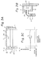
- Figures 3A and 3B show an embodiment of the present invention.
- the reference numeral 22 designates heating means, i.e., a heater, provided near the supply port 7A of a first supply tube 7.
- a first temperature sensor 23 which is first temperature detecting means is provided on the first supply tube 7 downstream of the heater 22, and a second temperature sensor 24 which is second temperature detecting means is provided near the substantially central portion of a common liquid chamber 2.
- the temperature differance ⁇ t between the temperature T1 detected by the first temperature sensor 23 and the temperature T2 detected by the second temperature sensor 24 is controlled so as to be within a predetermined temperature range as shown in Figure 3C.
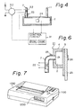
- FIG 4 shows the construction of a circuit for carrying out the above-described temperature control.
- the reference numeral 31 denotes a control circuit provided with the function of a CPU and having memory devices ROM and RAM.
- the reference numeral 32 designates switching means for switching on and off the heater 22.
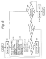
- step S1 the switching means 32 is switched “on” to supply electric power to the heater 22, and the steps S2 and S3, the detected temperatures T1 and T2 from the first temperature sensor 23 and the second temperature sensor 24 are read, respectively.
- step S6 If it is thus judged that the temperature difference ⁇ t is more than the temperature t max , advance is made to step S6, where the switching means 32 is switched "off" and the supply of electric power to the heater 22 is stopped, and return is made to step S2, and at the ensuring steps S3-S5, the temperature difference ⁇ t becoming lower than the temperature t max is waited for. Also, if at step S5, it is judged that the temperature difference ⁇ t is lower than the temperature t max , branching-off is made to step S7, where whether the temperature difference ⁇ t is less than the minimum allowed limit temperature t min is judged.
- step S7 If at step S7, it is judged that the temperature difference ⁇ t is less than the temperature t min , return is made to step S1, where electric power is supplied to the heater 22, whereafter step S2 and the subsequent steps are repeated, and if the temperature difference ⁇ t is higher than the temperature t min , advance is further made to step S8, where whether recording should be continued is judged. If it is thus judged that recording should be continued, return is made to step S2, and if it is judged that recording need not be continued, the supply of electric power to the heater 22 is stopped at step S9.
- the second temperature sensor 24 is provided near the substantially central portion in the common liquid chamber 2, but alternatively, as shown in Figure 6, the second temperature sensor 24 may be provided, for example, along the head supporting plate 25 of the recording head near the central portion thereof.
- the second temperature sensor is provided near the substantially central portion of the common liquid chamber or the head supporting plate so as to be suitable for remarkably grasping the temperature difference, but of course, the location thereof is not limited thereto if it is a location which enables the temperature difference ⁇ t to be clearly recognized.
- the present invention covers the following various modifications if it is a head capable of controlling the temperature of recording liquid in conformity with the difference between the temperature detected by the first temperature sensor and the temperature detected by the second temperature sensor:
- the first and second temperature sensor may be provided inside or outside the liquid path.
- the so-called full multitype liquid injection recording head has been mentioned as one of the most preferable embodiments of the present invention, whereas the present invention is not always restricted to the head of this type, but is also applicable to a head in which there may arise the aforementioned problem peculiar to the prior art due to the partiality of the temperature distribution of the recording liquid in the liquid chamber, i.e., for example, a head which has a plurality of discharge openings but is not of the full multitype.
- a head has been mentioned in which the direction in which recording liquid is discharged from the discharge opening substantially the same as the direction in which recording liquid is supplied to the location in the liquid path at which the energy generating means is provided, whereas the present invention is not restricted thereto.
- the present invention is also applicable, for example, to a head in which the direction in which recording liquid is discharged from the discharged opening differs from the direction in which recording liquid is supplied to the location in the liquid path at which the energy generating means is provided (for example, said two directions are substantially perpendicular to each other).
- FIG. 7 is a schematic perspective view of a liquid injection recording apparatus provided with the above-described liquid injection recording head.
- the reference numeral 1000 designates the apparatus body
- the reference numeral 1100 denotes a power source switch
- the reference numeral 1200 designates an operation panel.
- means for heating the recording liquid is provided in the supply tube near the recording liquid supply port provided in the common liquid chamber and therefore, it becomes possible to suppress the temperature gradient of the recording liquid in the common liquid chamber, and the variation in the size of formed recording liquid droplets can be suppressed to thereby eliminate the density difference of record on the recording material, and further, if said heating means is controlled so as to be switched on and off in association with the temperature of the recording liquid in the common liquid chamber and hear the supply port, recording can be carried out more effectively and thus, a liquid injection recording head particularly suitable for the full multitype can be provided.
Landscapes
- Engineering & Computer Science (AREA)
- Quality & Reliability (AREA)
- Ink Jet (AREA)
- Particle Formation And Scattering Control In Inkjet Printers (AREA)
Priority Applications (1)
| Application Number | Priority Date | Filing Date | Title |
|---|---|---|---|
| EP93201799A EP0577186B1 (de) | 1987-11-20 | 1988-11-18 | Aufzeichnungskopf mit Flüssigkeitseinspritzung und Aufzeichnungsgerät damit versehen |
Applications Claiming Priority (2)
| Application Number | Priority Date | Filing Date | Title |
|---|---|---|---|
| JP291965/87 | 1987-11-20 | ||
| JP62291965A JP2801196B2 (ja) | 1987-11-20 | 1987-11-20 | 液体噴射装置 |
Related Child Applications (1)
| Application Number | Title | Priority Date | Filing Date |
|---|---|---|---|
| EP93201799.9 Division-Into | 1993-06-22 |
Publications (3)
| Publication Number | Publication Date |
|---|---|
| EP0317342A2 true EP0317342A2 (de) | 1989-05-24 |
| EP0317342A3 EP0317342A3 (en) | 1989-08-16 |
| EP0317342B1 EP0317342B1 (de) | 1995-02-15 |
Family
ID=17775755
Family Applications (2)
| Application Number | Title | Priority Date | Filing Date |
|---|---|---|---|
| EP88310920A Expired - Lifetime EP0317342B1 (de) | 1987-11-20 | 1988-11-18 | Druckkopf für Aufzeichnungsgerät mit Flüssigkeitseinspritzung |
| EP93201799A Expired - Lifetime EP0577186B1 (de) | 1987-11-20 | 1988-11-18 | Aufzeichnungskopf mit Flüssigkeitseinspritzung und Aufzeichnungsgerät damit versehen |
Family Applications After (1)
| Application Number | Title | Priority Date | Filing Date |
|---|---|---|---|
| EP93201799A Expired - Lifetime EP0577186B1 (de) | 1987-11-20 | 1988-11-18 | Aufzeichnungskopf mit Flüssigkeitseinspritzung und Aufzeichnungsgerät damit versehen |
Country Status (4)
| Country | Link |
|---|---|
| US (1) | US5006867A (de) |
| EP (2) | EP0317342B1 (de) |
| JP (1) | JP2801196B2 (de) |
| DE (2) | DE3853047T2 (de) |
Cited By (5)
| Publication number | Priority date | Publication date | Assignee | Title |
|---|---|---|---|---|
| EP0416557A1 (de) * | 1989-09-05 | 1991-03-13 | Canon Kabushiki Kaisha | FlÀ¼ssigkeitsstrahlaufzeichnungskopf |
| EP0440499A1 (de) * | 1990-02-02 | 1991-08-07 | Canon Kabushiki Kaisha | Flüssigkeitsstrahlaufzeichnungskopf und Gerät |
| WO1993017870A1 (en) * | 1992-03-12 | 1993-09-16 | Willett International Limited | Temperature control system |
| EP2282893A4 (de) * | 2008-05-19 | 2011-05-04 | Hewlett Packard Development Co | Versorgungsrohrverbinder zur verbindung mit einem tintenbehälter |
| US8636345B2 (en) | 2008-05-19 | 2014-01-28 | Hewlett-Packard Development Company, L.P. | Supply tube connectors for connection with an ink container |
Families Citing this family (40)
| Publication number | Priority date | Publication date | Assignee | Title |
|---|---|---|---|---|
| EP0445526B1 (de) * | 1990-02-02 | 1995-05-24 | Canon Kabushiki Kaisha | Tintenstrahl-Aufzeichnungsgerät |
| US5808632A (en) * | 1990-02-02 | 1998-09-15 | Canon Kabushiki Kaisha | Recording apparatus and method using ink jet recording head |
| JP2752491B2 (ja) * | 1990-02-02 | 1998-05-18 | キヤノン株式会社 | 液体噴射記録装置 |
| JP2891748B2 (ja) * | 1990-06-15 | 1999-05-17 | キヤノン株式会社 | インクジェットヘッドの駆動方法 |
| US5530987A (en) * | 1992-07-24 | 1996-07-02 | The Babcock & Wilcox Company | Condensate drain controller |
| EP0585890B1 (de) * | 1992-09-01 | 1997-12-29 | Canon Kabushiki Kaisha | Farbstrahldruckkopf und zugehöriges Farbstrahlgerät |
| EP0594110B1 (de) * | 1992-10-20 | 2000-02-02 | Canon Kabushiki Kaisha | Farbstrahldruckkopf, dessen Herstellungsverfahren und zugehöriges Farbstrahlgerät |
| JP3535885B2 (ja) * | 1992-12-16 | 2004-06-07 | セイコーエプソン株式会社 | インクジェット式記録装置 |
| US5745136A (en) * | 1993-04-16 | 1998-04-28 | Canon Kabushiki Kaishi | Liquid jet head, and liquid jet apparatus therefor |
| US5646655A (en) | 1993-08-31 | 1997-07-08 | Canon Kabushiki Kaisha | Recording apparatus and temperature detecting method therefor |
| US5623292A (en) * | 1993-12-17 | 1997-04-22 | Videojet Systems International, Inc. | Temperature controller for ink jet printing |
| JP3347502B2 (ja) * | 1993-12-28 | 2002-11-20 | キヤノン株式会社 | インクジェットヘッドおよびインクジェット装置 |
| SG52140A1 (en) * | 1994-03-04 | 1998-09-28 | Canon Kk | Ink jet recording head and method of manufacture therefor and laser processing apparatus and ink jet recording apparatus |
| SG59905A1 (en) | 1994-03-04 | 1999-02-22 | Canon Kk | An ink jet recording apparatus |
| SG44309A1 (en) * | 1994-03-04 | 1997-12-19 | Canon Kk | An ink jet recording apparatus |
| DE69525669T2 (de) * | 1994-03-29 | 2002-08-08 | Canon K.K., Tokio/Tokyo | Substrat für Tintenstrahlkopf, Tintenstrahlkopf, Tintenstrahlschreiber und Tintenstrahlgerät |
| JP3323664B2 (ja) * | 1994-09-09 | 2002-09-09 | キヤノン株式会社 | プリント装置 |
| JP3174225B2 (ja) * | 1994-10-27 | 2001-06-11 | キヤノン株式会社 | 記録ヘッド及び該記録ヘッドを用いた記録方法及び装置 |
| JP3176249B2 (ja) * | 1995-04-28 | 2001-06-11 | キヤノン株式会社 | インクジェット記録ヘッド、インクジェット記録装置および情報処理システム |
| US5936650A (en) * | 1995-05-24 | 1999-08-10 | Hewlett Packard Company | Ink delivery system for ink-jet pens |
| EP1563998B8 (de) | 1996-06-26 | 2010-10-20 | Canon Kabushiki Kaisha | Aufzeichnungskopf und Aufzeichnungsapparat unter Verwendung desselben |
| JPH1024582A (ja) * | 1996-07-12 | 1998-01-27 | Canon Inc | 液体吐出ヘッド並びに該液体吐出ヘッドの回復方法及び製造方法、並びに該液体吐出ヘッドを用いた液体吐出装置 |
| JP2000043271A (ja) | 1997-11-14 | 2000-02-15 | Canon Inc | インクジェット記録ヘッド、その製造方法及び該インクジェット記録ヘッドを具備する記録装置 |
| US6211970B1 (en) | 1998-11-24 | 2001-04-03 | Lexmark International, Inc. | Binary printer with halftone printing temperature correction |
| US6213579B1 (en) | 1998-11-24 | 2001-04-10 | Lexmark International, Inc. | Method of compensation for the effects of thermally-induced droplet size variations in ink drop printers |
| JP2001058407A (ja) | 1999-08-23 | 2001-03-06 | Canon Inc | インクジェット記録装置およびインクジェット記録ヘッド |
| US6705691B2 (en) | 2000-01-14 | 2004-03-16 | Canon Kabushiki Kaisha | Ink-jet printing method and ink-jet printer |
| JP2004262233A (ja) * | 2003-02-13 | 2004-09-24 | Konica Minolta Holdings Inc | インクジェットプリンタ |
| US7264326B2 (en) * | 2004-05-25 | 2007-09-04 | Brother Kogyo Kabushiki Kaisha | Inkjet printer |
| JP4290154B2 (ja) * | 2004-12-08 | 2009-07-01 | キヤノン株式会社 | 液体吐出記録ヘッドおよびインクジェット記録装置 |
| JP5201969B2 (ja) * | 2006-12-13 | 2013-06-05 | キヤノン株式会社 | インクジェット記録装置及びインクジェット記録装置における記録方法 |
| JP4618375B2 (ja) * | 2008-12-26 | 2011-01-26 | ブラザー工業株式会社 | 液体吐出ヘッド |
| JP5505272B2 (ja) * | 2010-11-17 | 2014-05-28 | セイコーエプソン株式会社 | 液体噴射装置 |
| JP6094263B2 (ja) * | 2013-02-28 | 2017-03-15 | セイコーエプソン株式会社 | 液体噴射装置 |
| JP5773014B2 (ja) * | 2014-03-18 | 2015-09-02 | セイコーエプソン株式会社 | 液体噴射装置、液体噴射方法 |
| JP6669393B2 (ja) | 2016-03-25 | 2020-03-18 | キヤノン株式会社 | 液体吐出ヘッド、液体吐出装置、および液体吐出ヘッドの温度制御方法 |
| JP2018161787A (ja) * | 2017-03-24 | 2018-10-18 | 東芝テック株式会社 | 液体吐出ヘッド及び液体吐出装置 |
| DE102020109033A1 (de) | 2020-04-01 | 2021-10-07 | CADIS Engineering GmbH | Tinten-Versorgungsanordnung für die Druckköpfe eines Tintenstrahldruckers |
| CN112212066A (zh) * | 2020-10-09 | 2021-01-12 | 陈科 | 一种减速水阀 |
| US11697289B2 (en) | 2020-12-01 | 2023-07-11 | Toshiba Tec Kabushiki Kaisha | Liquid circulation device and liquid discharge apparatus |
Family Cites Families (8)
| Publication number | Priority date | Publication date | Assignee | Title |
|---|---|---|---|---|
| US4106030A (en) * | 1977-02-14 | 1978-08-08 | Recognition Equipment Incorporated | Ink jet printer ink heater |
| US4364059A (en) * | 1979-12-17 | 1982-12-14 | Ricoh Company, Ltd. | Ink jet printing apparatus |
| JPS5719337A (en) * | 1980-07-07 | 1982-02-01 | Kobe Steel Ltd | Pellet having double structure for iron manufacture |
| JPS57146681A (en) * | 1981-03-05 | 1982-09-10 | Fujitsu Ltd | Detecting method for abnormality in laser printer |
| US4459469A (en) * | 1981-05-15 | 1984-07-10 | Ricoh Company, Ltd. | Ink temperature control apparatus for ink jet printing apparatus |
| US4590362A (en) * | 1983-04-20 | 1986-05-20 | Ricoh Company, Ltd. | Drive circuit for temperature control heater in ink jet printer |
| JPH0712671B2 (ja) * | 1983-06-21 | 1995-02-15 | キヤノン株式会社 | インクジェットプリンタ |
| JPH0729427B2 (ja) * | 1985-12-20 | 1995-04-05 | キヤノン株式会社 | 液体噴射記録装置 |
-
1987
- 1987-11-20 JP JP62291965A patent/JP2801196B2/ja not_active Expired - Fee Related
-
1988
- 1988-11-18 EP EP88310920A patent/EP0317342B1/de not_active Expired - Lifetime
- 1988-11-18 DE DE3853047T patent/DE3853047T2/de not_active Expired - Fee Related
- 1988-11-18 EP EP93201799A patent/EP0577186B1/de not_active Expired - Lifetime
- 1988-11-18 DE DE3856048T patent/DE3856048T2/de not_active Expired - Fee Related
-
1990
- 1990-05-07 US US07/518,238 patent/US5006867A/en not_active Expired - Lifetime
Cited By (7)
| Publication number | Priority date | Publication date | Assignee | Title |
|---|---|---|---|---|
| EP0416557A1 (de) * | 1989-09-05 | 1991-03-13 | Canon Kabushiki Kaisha | FlÀ¼ssigkeitsstrahlaufzeichnungskopf |
| US6231152B1 (en) | 1989-09-05 | 2001-05-15 | Canon Kabushiki Kaisha | Ink jet recording method employing control of ink temperature |
| EP0440499A1 (de) * | 1990-02-02 | 1991-08-07 | Canon Kabushiki Kaisha | Flüssigkeitsstrahlaufzeichnungskopf und Gerät |
| US5175567A (en) * | 1990-02-02 | 1992-12-29 | Canon Kabushiki Kaisha | Recording apparatus and recording head having an improved discharge post arrangement |
| WO1993017870A1 (en) * | 1992-03-12 | 1993-09-16 | Willett International Limited | Temperature control system |
| EP2282893A4 (de) * | 2008-05-19 | 2011-05-04 | Hewlett Packard Development Co | Versorgungsrohrverbinder zur verbindung mit einem tintenbehälter |
| US8636345B2 (en) | 2008-05-19 | 2014-01-28 | Hewlett-Packard Development Company, L.P. | Supply tube connectors for connection with an ink container |
Also Published As
| Publication number | Publication date |
|---|---|
| EP0317342A3 (en) | 1989-08-16 |
| DE3856048D1 (de) | 1997-11-20 |
| DE3853047D1 (de) | 1995-03-23 |
| EP0577186A1 (de) | 1994-01-05 |
| EP0577186B1 (de) | 1997-10-15 |
| US5006867A (en) | 1991-04-09 |
| EP0317342B1 (de) | 1995-02-15 |
| DE3856048T2 (de) | 1998-03-26 |
| JP2801196B2 (ja) | 1998-09-21 |
| DE3853047T2 (de) | 1995-07-06 |
| JPH01133748A (ja) | 1989-05-25 |
Similar Documents
| Publication | Publication Date | Title |
|---|---|---|
| US5006867A (en) | Recording head for an ink jet recording apparatus having a plurality of temperature detection elements | |
| EP0715960B1 (de) | Aufzeichnungskopf mit Flüssigkeitsausstoss | |
| KR100209498B1 (ko) | 서로 다른 열팽창 계수 특성을 지닌 다중 멤브레인을 갖는 잉크젯 프린터의 분사장치 | |
| EP0613780B2 (de) | Verfahren und Vorrichtung zum Erwärmen der Tinte in einem Farbstrahldruckkopf | |
| US5291215A (en) | Ink jet recording apparatus with a thermally stable ink jet recording head | |
| CA1275855C (en) | Printhead for an ink jet printer | |
| JP5213367B2 (ja) | インクジェット記録ヘッド | |
| US5815185A (en) | Ink flow heat exchanger for inkjet printhead | |
| US5992991A (en) | Ink jet recording device with AC and DC heaters selectively used for hot melt ink | |
| KR100189155B1 (ko) | 잉크젯 프린터의 분사 장치 및 분사 방법 | |
| JP2002200755A (ja) | バブルジェット(登録商標)方式のインクジェットプリントヘッド | |
| JP2793372B2 (ja) | インクジェット記録ヘッド,該ヘッド用基板およびインクジェット記録装置 | |
| JPH0315557A (ja) | インクジェット記録装置 | |
| US7434917B2 (en) | Ink jet recording head having temperature control heaters and nozzle arrays of differing discharge amounts | |
| JP2885994B2 (ja) | インクジェット記録装置 | |
| US6186617B1 (en) | Device for storing and supplying active liquid in ink jet printhead | |
| JPH03234636A (ja) | インクジェット記録装置 | |
| US5881646A (en) | Method and apparatus for image recording by emitting evaporated ink onto a recording medium | |
| EP1403048B1 (de) | Anlauf mit niedriger Auffangsspannung | |
| JPH06320735A (ja) | インクジェット記録装置および記録方法 | |
| JP2002079665A (ja) | インクジェット式記録装置及び記録方法 | |
| JP3261630B2 (ja) | インクジェット記録装置 | |
| US20040090484A1 (en) | Inkjet recording apparatus | |
| JPH03218841A (ja) | インクジェット記録装置 | |
| JPH03234632A (ja) | インクジェット記録装置 |
Legal Events
| Date | Code | Title | Description |
|---|---|---|---|
| PUAI | Public reference made under article 153(3) epc to a published international application that has entered the european phase |
Free format text: ORIGINAL CODE: 0009012 |
|
| AK | Designated contracting states |
Kind code of ref document: A2 Designated state(s): DE FR GB IT |
|
| PUAL | Search report despatched |
Free format text: ORIGINAL CODE: 0009013 |
|
| AK | Designated contracting states |
Kind code of ref document: A3 Designated state(s): DE FR GB IT |
|
| 17P | Request for examination filed |
Effective date: 19900110 |
|
| 17Q | First examination report despatched |
Effective date: 19910716 |
|
| GRAA | (expected) grant |
Free format text: ORIGINAL CODE: 0009210 |
|
| ITF | It: translation for a ep patent filed | ||
| AK | Designated contracting states |
Kind code of ref document: B1 Designated state(s): DE FR GB IT |
|
| XX | Miscellaneous (additional remarks) |
Free format text: TEILANMELDUNG 93201799.9 EINGEREICHT AM 18/11/88. |
|
| REF | Corresponds to: |
Ref document number: 3853047 Country of ref document: DE Date of ref document: 19950323 |
|
| ET | Fr: translation filed | ||
| PLBE | No opposition filed within time limit |
Free format text: ORIGINAL CODE: 0009261 |
|
| STAA | Information on the status of an ep patent application or granted ep patent |
Free format text: STATUS: NO OPPOSITION FILED WITHIN TIME LIMIT |
|
| 26N | No opposition filed | ||
| REG | Reference to a national code |
Ref country code: GB Ref legal event code: IF02 |
|
| PGFP | Annual fee paid to national office [announced via postgrant information from national office to epo] |
Ref country code: GB Payment date: 20041104 Year of fee payment: 17 |
|
| PGFP | Annual fee paid to national office [announced via postgrant information from national office to epo] |
Ref country code: FR Payment date: 20041126 Year of fee payment: 17 |
|
| PGFP | Annual fee paid to national office [announced via postgrant information from national office to epo] |
Ref country code: DE Payment date: 20050121 Year of fee payment: 17 |
|
| PG25 | Lapsed in a contracting state [announced via postgrant information from national office to epo] |
Ref country code: IT Free format text: LAPSE BECAUSE OF NON-PAYMENT OF DUE FEES;WARNING: LAPSES OF ITALIAN PATENTS WITH EFFECTIVE DATE BEFORE 2007 MAY HAVE OCCURRED AT ANY TIME BEFORE 2007. THE CORRECT EFFECTIVE DATE MAY BE DIFFERENT FROM THE ONE RECORDED. Effective date: 20051118 Ref country code: GB Free format text: LAPSE BECAUSE OF NON-PAYMENT OF DUE FEES Effective date: 20051118 |
|
| PG25 | Lapsed in a contracting state [announced via postgrant information from national office to epo] |
Ref country code: DE Free format text: LAPSE BECAUSE OF NON-PAYMENT OF DUE FEES Effective date: 20060601 |
|
| GBPC | Gb: european patent ceased through non-payment of renewal fee |
Effective date: 20051118 |
|
| PG25 | Lapsed in a contracting state [announced via postgrant information from national office to epo] |
Ref country code: FR Free format text: LAPSE BECAUSE OF NON-PAYMENT OF DUE FEES Effective date: 20060731 |
|
| REG | Reference to a national code |
Ref country code: FR Ref legal event code: ST Effective date: 20060731 |