EP0416557A1 - FlÀ¼ssigkeitsstrahlaufzeichnungskopf - Google Patents
FlÀ¼ssigkeitsstrahlaufzeichnungskopf Download PDFInfo
- Publication number
- EP0416557A1 EP0416557A1 EP90117007A EP90117007A EP0416557A1 EP 0416557 A1 EP0416557 A1 EP 0416557A1 EP 90117007 A EP90117007 A EP 90117007A EP 90117007 A EP90117007 A EP 90117007A EP 0416557 A1 EP0416557 A1 EP 0416557A1
- Authority
- EP
- European Patent Office
- Prior art keywords
- recording
- liquid
- temperature
- diameter
- dots
- Prior art date
- Legal status (The legal status is an assumption and is not a legal conclusion. Google has not performed a legal analysis and makes no representation as to the accuracy of the status listed.)
- Granted
Links
- 239000007788 liquid Substances 0.000 title claims abstract description 105
- 239000000758 substrate Substances 0.000 claims abstract description 20
- 238000010438 heat treatment Methods 0.000 claims abstract description 19
- 238000007599 discharging Methods 0.000 claims abstract description 5
- 238000000034 method Methods 0.000 description 8
- MTHSVFCYNBDYFN-UHFFFAOYSA-N diethylene glycol Chemical compound OCCOCCO MTHSVFCYNBDYFN-UHFFFAOYSA-N 0.000 description 6
- 238000010276 construction Methods 0.000 description 4
- 239000006229 carbon black Substances 0.000 description 2
- XLYOFNOQVPJJNP-UHFFFAOYSA-N water Substances O XLYOFNOQVPJJNP-UHFFFAOYSA-N 0.000 description 2
- 230000015572 biosynthetic process Effects 0.000 description 1
- 238000010586 diagram Methods 0.000 description 1
- 238000012423 maintenance Methods 0.000 description 1
- 238000004519 manufacturing process Methods 0.000 description 1
- 238000001454 recorded image Methods 0.000 description 1
- 239000002904 solvent Substances 0.000 description 1
- 239000010409 thin film Substances 0.000 description 1
Images



Classifications
-
- B—PERFORMING OPERATIONS; TRANSPORTING
- B41—PRINTING; LINING MACHINES; TYPEWRITERS; STAMPS
- B41J—TYPEWRITERS; SELECTIVE PRINTING MECHANISMS, i.e. MECHANISMS PRINTING OTHERWISE THAN FROM A FORME; CORRECTION OF TYPOGRAPHICAL ERRORS
- B41J2/00—Typewriters or selective printing mechanisms characterised by the printing or marking process for which they are designed
- B41J2/005—Typewriters or selective printing mechanisms characterised by the printing or marking process for which they are designed characterised by bringing liquid or particles selectively into contact with a printing material
- B41J2/01—Ink jet
- B41J2/015—Ink jet characterised by the jet generation process
- B41J2/04—Ink jet characterised by the jet generation process generating single droplets or particles on demand
- B41J2/045—Ink jet characterised by the jet generation process generating single droplets or particles on demand by pressure, e.g. electromechanical transducers
- B41J2/04501—Control methods or devices therefor, e.g. driver circuits, control circuits
- B41J2/04528—Control methods or devices therefor, e.g. driver circuits, control circuits aiming at warming up the head
-
- B—PERFORMING OPERATIONS; TRANSPORTING
- B41—PRINTING; LINING MACHINES; TYPEWRITERS; STAMPS
- B41J—TYPEWRITERS; SELECTIVE PRINTING MECHANISMS, i.e. MECHANISMS PRINTING OTHERWISE THAN FROM A FORME; CORRECTION OF TYPOGRAPHICAL ERRORS
- B41J2/00—Typewriters or selective printing mechanisms characterised by the printing or marking process for which they are designed
- B41J2/005—Typewriters or selective printing mechanisms characterised by the printing or marking process for which they are designed characterised by bringing liquid or particles selectively into contact with a printing material
- B41J2/01—Ink jet
- B41J2/015—Ink jet characterised by the jet generation process
- B41J2/04—Ink jet characterised by the jet generation process generating single droplets or particles on demand
- B41J2/045—Ink jet characterised by the jet generation process generating single droplets or particles on demand by pressure, e.g. electromechanical transducers
- B41J2/04501—Control methods or devices therefor, e.g. driver circuits, control circuits
- B41J2/04563—Control methods or devices therefor, e.g. driver circuits, control circuits detecting head temperature; Ink temperature
-
- B—PERFORMING OPERATIONS; TRANSPORTING
- B41—PRINTING; LINING MACHINES; TYPEWRITERS; STAMPS
- B41J—TYPEWRITERS; SELECTIVE PRINTING MECHANISMS, i.e. MECHANISMS PRINTING OTHERWISE THAN FROM A FORME; CORRECTION OF TYPOGRAPHICAL ERRORS
- B41J2/00—Typewriters or selective printing mechanisms characterised by the printing or marking process for which they are designed
- B41J2/005—Typewriters or selective printing mechanisms characterised by the printing or marking process for which they are designed characterised by bringing liquid or particles selectively into contact with a printing material
- B41J2/01—Ink jet
- B41J2/015—Ink jet characterised by the jet generation process
- B41J2/04—Ink jet characterised by the jet generation process generating single droplets or particles on demand
- B41J2/045—Ink jet characterised by the jet generation process generating single droplets or particles on demand by pressure, e.g. electromechanical transducers
- B41J2/04501—Control methods or devices therefor, e.g. driver circuits, control circuits
- B41J2/0458—Control methods or devices therefor, e.g. driver circuits, control circuits controlling heads based on heating elements forming bubbles
-
- B—PERFORMING OPERATIONS; TRANSPORTING
- B41—PRINTING; LINING MACHINES; TYPEWRITERS; STAMPS
- B41J—TYPEWRITERS; SELECTIVE PRINTING MECHANISMS, i.e. MECHANISMS PRINTING OTHERWISE THAN FROM A FORME; CORRECTION OF TYPOGRAPHICAL ERRORS
- B41J2/00—Typewriters or selective printing mechanisms characterised by the printing or marking process for which they are designed
- B41J2/005—Typewriters or selective printing mechanisms characterised by the printing or marking process for which they are designed characterised by bringing liquid or particles selectively into contact with a printing material
- B41J2/01—Ink jet
- B41J2/135—Nozzles
- B41J2/14—Structure thereof only for on-demand ink jet heads
- B41J2002/14379—Edge shooter
Definitions
- This invention relates to a liquid jet recording head, and in particular to a liquid jet recording head in which the temperature of recording liquid is controlled, whereby the concentration of recorded images can be adjusted relative to various kinds of plain paper.
- the liquid jet recording methods can accomplish high-speed recording in that noises produced during recording are negligibly small, and moreover have recently been drawing attention in that they can accomplish recording without requiring any special process such as the fixation on so-called plain paper.
- the liquid jet recording method described, for example, in Japanese Laid-Open Patent Application No. 54-51837 or German Laid-Open Patent Application (DOLS) No. 2843064 has features differing from those of the other liquid jet recording methods in that heat energy is caused to act on liquid to obtain a driving force for discharging liquid droplets.
- this liquid jet recording method is such that liquid subjected to the action of heat energy causes a state change accompanied by a steep increase in volume and the recording liquid is discharged from a discharge port at the fore end of a recording head unit by an action force based on the state change, whereby flying droplets are formed and adhere as dots to a recording medium to thereby accomplish recording, and the liquid jet recording method disclosed in DOLS No. 2843064 has the feature that not only it is very effectively applied to the so-called drop-on demand recording method, but also it can easily embody a recording head of the full line type having multiorifice at a high density and therefore can provide images of high resolution and high quality at a high speed.
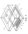
- FIG. 7 of the accompanying drawings shows an example of the liquid jet recording head according to the prior art.
- the reference numeral 1 designates the substrate portion of the recording head
- the reference numeral 2 denotes liquid paths formed in parallel on the substrate portion 1
- the reference numeral 3 designates a common liquid chamber connected to the liquid paths 2
- the reference numeral 4 denotes heat-acting portions disposed in the liquid paths 2.
- Electro-thermal converting members as heat energy generating means for causing recording liquid to the discharged as flying liquid droplets from discharge ports 5 are provided in the heat-acting portions 4.
- Each electro-thermal converting member has a pair of electrodes and heat generating resistance layers connected to these electrodes and generating heat, although they are not shown.
- the reference numeral 6 designates an upper lid member
- the reference numeral 7 denotes a recording liquid supply port formed in the upper lid member 6 over the common liquid chamber 3. Recording liquid is supplied from an outside recording liquid tank to the common liquid chamber 3 by a tube or the like through the supply port 7.
- the recording liquid directed from the common liquid chamber 3 to the liquid paths 2 is heated and gasified by the electro-thermal converting members in the heat-acting portions 4 being electrically energized, and a variation in the pressure thereof causes the recording liquid to be discharged as liquid droplets from the discharge ports 5 and shot on a recording medium to form dots, and an image is recorded by an aggregate of these dots.
- the prior-art liquid jet recording head as described above has suffered from the drawback that the diameter of liquid droplets discharged is fixed due to the limitations or the like in the manufacture of the head while, on the other hand, the rate of blur (the diameter of dots/the diameter of discharged liquid droplets) differs depending on the kinds of recording medium and accordingly, the recording concentration becomes diverse depending on the kinds of recording medium, but nevertheless, in the formation of discharged liquid droplets, no special consideration has been given to the speed thereof and the temperature of the recording liquid.
- the present invention provides a liquid jet recording head for selectively discharging recording liquid as liquid droplets from a plurality of discharge ports arranged in the main scanning direction along a substrate toward a recording medium to form dots on the recording medium and thereby accomplish recording, characterized in that provision is made of heating means for heating the recording liquid through the substrate, and temperature detecting means for detecting the temperature of the recording liquid, and said heating means is energized on the basis of the detected temperature from said temperature detecting means to keep the temperature of the recording liquid at a predetermined temperature, whereby the ratio of the diameter of said dots to the diameter of the liquid droplets can be maintained at a predetermined value.
- what rate of blur (the diameter of dots/the diameter of liquid droplets) can be obtained if at what degree the temperature of the recording liquid is kept can be known from the quality of the recording medium, the composition of the recording liquid and the arrangement density of the discharge ports in the recording head and therefore, by keeping such a temperature of the recording liquid that enables such a rate of blur to be obtained, an appropriate recording concentration can always be kept.
- FIG. 1 shows an embodiment of the present invention.
- temperature detecting means 8 is provided toward a liquid path 2 near the center of a common liquid chamber 3 on a substrate portion 1.
- a thermistor of good accuracy having a tolerance of the order of ⁇ 1°C is used as the temperature detecting means 8, but inexpensive means such as a thermocouple can also be used if recording density is not strictly controlled.
- the reference numeral 9 designates heaters as substrate heating means provided on both sides of a row of liquid paths on the substrate portion 1, and design is made such that recording liquid does not directly contact with these heaters 9.
- the heaters 9 may be ones capable of increasing the temperature of the substrate to about 60°C at highest in accordance with the temperature of the recording liquid, and these heaters 9 may be formed at a time by the thin film forming technique when heat generating resistance members are formed on heat-acting portions 4.
- a Si substrate is used for the substrate portion 1 so that heat from the heaters 9 may be readily transmitted to the recording liquid.
- Figure 2 diagrammatically shows a circuit construction for controlling the temperature of the recording liquid in the recording head 10 shown in Figure 1.
- the reference numeral 11 denotes temperature setting means capable of arbitrarily selecting and indicating the temperature of the recording liquid
- the reference numeral 12 designates temperature control means for comparing the detected temperature from the temperature detecting means 8 with the temperature input from the temperature setting means 11 and energizing the heating means 9 through a driver 13 so that the former temperature may be the set temperature.
- a recording liquid temperature at which there is provided the diameter of dots for keeping an appropriate recording concentration correspondingly thereto can be indicated through the temperature setting means. Thereafter, in accordance with that indicated temperature, the temperature of the recording liquid can be controlled by the temperature control means 12 so as to be kept at the temperature.
- a recording head having a recording density of 300 dpi, i.e., provided with 64 liquid paths 2 at a pitch of 84.7 ⁇ m and capable of providing discharged liquid droplets of a diameter 50 ⁇ m, and recording liquid of the following composition was used: Carbon black 3% Diethylene glycol 30% Water 67%
- the dot pitch is 84.7 ⁇ m and thus, if the diameter of dots is equal to or greater than the dot pitch, proper recording will be accomplished in principle.
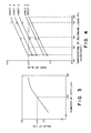
- the recording concentration varies in accordance with the diameter of dots as shown in Figure 3, but in the case of the present embodiment, the value of O.D. can be kept at 1.15 if the diameter of dots is 100 ⁇ m. In this case, the diameter of discharged liquid droplets is 50 ⁇ m and therefore, the rate of blur is 2.0.
- recording head having a recording density of 400 dpi,.i.e., provided with 256 liquid paths 2 at a pitch of 63.5 ⁇ m and capable of providing discharged liquid droplets of a diameter 40 ⁇ m, and as the heating means in this case, a large heater was brought into intimate contact with the back side of the substrate portion 1.
- the substrate becomes larger than in the first embodiment and a temperature gradient is liable to occur between the liquid path in the central portion and the liquid paths in the opposite end portions.
- the range of the controlled temperature for heating the substrate portion 1 was 25°C - 60°C.
- the relation between the recording concentration and the diameter of dots is such as shown in Figure 5 and therefore, to keep the value of O.D. at 1.15, it is necessary that the diameter of dots be 85 ⁇ m.
- the temperature of the recording liquid for keeping the rate of blur at 2.13 was as follows for the five kinds of paper A - E:
- heating means for heating the recording liquid through a substrate, and temperature detecting means for detecting the temperature of the recording liquid before discharged, and the heating means is energized on the basis of the detected temperature from the temperature detecting means to keep the temperature of the recording liquid at a predetermined temperature, whereby the ratio of the diameter of dots to the diameter of liquid droplets can be maintained at a predetermined value and therefore, the maintenance of an appropriate recording concentration has become possible in conformity with the recording medium, the recording liquid and the recording density.
- a liquid jet recording head for selectively discharging recording liquid as liquid droplets from a plurality of discharge ports arranged in the main scanning direction along a substrate toward a recording medium to form dots on the recording medium and thereby accomplish recording is provided with heating means for heating the recording liquid through the substrate, and temperature detecting means for detecting the temperature of the recording liquid.
- the heating means is energized on the basis of the detected temperature from the temperature detecting means to keep the temperature of the recording liquid at a predetermined temperature, whereby the ratio of the diameter of the dots to the diameter of the liquid droplets can be maintained at a predetermined value.
Landscapes
- Particle Formation And Scattering Control In Inkjet Printers (AREA)
- Ink Jet (AREA)
- Paper (AREA)
- Printing Methods (AREA)
Applications Claiming Priority (2)
| Application Number | Priority Date | Filing Date | Title |
|---|---|---|---|
| JP228202/89 | 1989-09-05 | ||
| JP1228202A JP2810142B2 (ja) | 1989-09-05 | 1989-09-05 | インクジェット記録方法 |
Publications (2)
| Publication Number | Publication Date |
|---|---|
| EP0416557A1 true EP0416557A1 (de) | 1991-03-13 |
| EP0416557B1 EP0416557B1 (de) | 1997-12-17 |
Family
ID=16872800
Family Applications (1)
| Application Number | Title | Priority Date | Filing Date |
|---|---|---|---|
| EP90117007A Expired - Lifetime EP0416557B1 (de) | 1989-09-05 | 1990-09-04 | Verfahren zum Bedrucken unterschiedlicher Druckmedien |
Country Status (6)
| Country | Link |
|---|---|
| US (1) | US6231152B1 (de) |
| EP (1) | EP0416557B1 (de) |
| JP (1) | JP2810142B2 (de) |
| AT (1) | ATE161226T1 (de) |
| DE (1) | DE69031821T2 (de) |
| ES (1) | ES2109917T3 (de) |
Cited By (7)
| Publication number | Priority date | Publication date | Assignee | Title |
|---|---|---|---|---|
| EP0471545A3 (en) * | 1990-08-14 | 1992-04-15 | Canon Kabushiki Kaisha | Recording apparatus and recording method using ink jet recording head |
| FR2686831A1 (fr) * | 1993-01-26 | 1993-08-06 | Inkjet Systems Gmbh Co Kg | Procede et dispositif pour surveiller le fonctionnement de tetes d'impression a encre. |
| EP0600648A3 (de) * | 1992-11-30 | 1995-01-04 | Hewlett Packard Co | Verfahren und Vorrichtung zur Überwachung von Thermo-Tintenstrahl-Druckern. |
| US5673069A (en) * | 1991-05-01 | 1997-09-30 | Hewlett-Packard Company | Method and apparatus for reducing the size of drops ejected from a thermal ink jet printhead |
| EP1186415A1 (de) * | 2000-09-06 | 2002-03-13 | Canon Kabushiki Kaisha | Tintenstrahlaufzeichnungskopf und Tintenstrahlaufzeichnungsvorrichtung |
| EP1208986A1 (de) | 2000-11-27 | 2002-05-29 | Océ-Technologies B.V. | Tintenstrahldrucksystem, Tintenbehälter und Herstellungsverfahren |
| EP1208988A1 (de) | 2000-11-27 | 2002-05-29 | Océ-Technologies B.V. | Tintenstrahldrucksystem, Tintenbehälter und Herstellungsverfahren |
Families Citing this family (4)
| Publication number | Priority date | Publication date | Assignee | Title |
|---|---|---|---|---|
| US6234599B1 (en) | 1988-07-26 | 2001-05-22 | Canon Kabushiki Kaisha | Substrate having a built-in temperature detecting element, and ink jet apparatus having the same |
| DE19523870A1 (de) * | 1995-06-30 | 1997-01-02 | Mann & Hummel Filter | Ansaugeinrichtung aus thermoplastischem Kunststoff |
| CN100376398C (zh) * | 2004-10-29 | 2008-03-26 | 明基电通股份有限公司 | 可寻找喷墨头的喷墨晶片的理想起点温度的方法及喷墨头 |
| US8439468B2 (en) * | 2008-12-19 | 2013-05-14 | Canon Kabushiki Kaisha | Inkjet print apparatus and inkjet print method |
Citations (4)
| Publication number | Priority date | Publication date | Assignee | Title |
|---|---|---|---|---|
| DE2943164A1 (de) * | 1978-10-26 | 1980-05-08 | Canon Kk | Tintenstrahl-aufzeichnungsvorrichtung |
| DE3717294A1 (de) * | 1986-06-10 | 1987-12-17 | Seiko Epson Corp | Tintenstrahlaufzeichnungsgeraet |
| EP0250266A2 (de) * | 1986-06-20 | 1987-12-23 | Canon Kabushiki Kaisha | Tintenstrahlaufzeichnungsverfahren |
| EP0317342A2 (de) * | 1987-11-20 | 1989-05-24 | Canon Kabushiki Kaisha | Druckkopf für Aufzeichnungsgerät mit Flüssigkeitseinspritzung |
Family Cites Families (14)
| Publication number | Priority date | Publication date | Assignee | Title |
|---|---|---|---|---|
| JPS5451837A (en) | 1977-09-30 | 1979-04-24 | Ricoh Co Ltd | Ink jet head device |
| CA1127227A (en) | 1977-10-03 | 1982-07-06 | Ichiro Endo | Liquid jet recording process and apparatus therefor |
| GB2038883B (en) | 1978-11-09 | 1982-12-08 | Standard Telephones Cables Ltd | Metallizing semiconductor devices |
| JPS58220757A (ja) * | 1982-06-18 | 1983-12-22 | Canon Inc | 液体噴射記録装置 |
| US4542059A (en) * | 1982-08-23 | 1985-09-17 | Canon Kabushiki Kaisha | Recording medium |
| JPH062417B2 (ja) * | 1983-08-31 | 1994-01-12 | キヤノン株式会社 | インクジェット記録装置 |
| JPS6277946A (ja) * | 1985-10-01 | 1987-04-10 | Canon Inc | インクジエツト記録装置 |
| JPS62113564A (ja) * | 1985-11-13 | 1987-05-25 | Canon Inc | インクジエツト記録装置 |
| JPS6327271A (ja) * | 1986-07-18 | 1988-02-04 | Shinko Electric Co Ltd | 熱転写式プリンタ |
| JPS6341153A (ja) * | 1986-08-06 | 1988-02-22 | Canon Inc | 液体噴射記録方法 |
| US4899180A (en) | 1988-04-29 | 1990-02-06 | Xerox Corporation | On chip heater element and temperature sensor |
| US5225849A (en) * | 1988-06-17 | 1993-07-06 | Canon Kabushiki Kaisha | Image recording apparatus and method for performing recording by making ink adhere to a recording medium and incorporating image data correction |
| US5175565A (en) * | 1988-07-26 | 1992-12-29 | Canon Kabushiki Kaisha | Ink jet substrate including plural temperature sensors and heaters |
| US5107276A (en) * | 1989-07-03 | 1992-04-21 | Xerox Corporation | Thermal ink jet printhead with constant operating temperature |
-
1989
- 1989-09-05 JP JP1228202A patent/JP2810142B2/ja not_active Expired - Fee Related
-
1990
- 1990-09-04 ES ES90117007T patent/ES2109917T3/es not_active Expired - Lifetime
- 1990-09-04 AT AT90117007T patent/ATE161226T1/de not_active IP Right Cessation
- 1990-09-04 EP EP90117007A patent/EP0416557B1/de not_active Expired - Lifetime
- 1990-09-04 DE DE69031821T patent/DE69031821T2/de not_active Expired - Fee Related
-
1995
- 1995-01-23 US US08/376,667 patent/US6231152B1/en not_active Expired - Fee Related
Patent Citations (4)
| Publication number | Priority date | Publication date | Assignee | Title |
|---|---|---|---|---|
| DE2943164A1 (de) * | 1978-10-26 | 1980-05-08 | Canon Kk | Tintenstrahl-aufzeichnungsvorrichtung |
| DE3717294A1 (de) * | 1986-06-10 | 1987-12-17 | Seiko Epson Corp | Tintenstrahlaufzeichnungsgeraet |
| EP0250266A2 (de) * | 1986-06-20 | 1987-12-23 | Canon Kabushiki Kaisha | Tintenstrahlaufzeichnungsverfahren |
| EP0317342A2 (de) * | 1987-11-20 | 1989-05-24 | Canon Kabushiki Kaisha | Druckkopf für Aufzeichnungsgerät mit Flüssigkeitseinspritzung |
Cited By (11)
| Publication number | Priority date | Publication date | Assignee | Title |
|---|---|---|---|---|
| EP0471545A3 (en) * | 1990-08-14 | 1992-04-15 | Canon Kabushiki Kaisha | Recording apparatus and recording method using ink jet recording head |
| US5307093A (en) * | 1990-08-14 | 1994-04-26 | Canon Kabushiki Kaisha | Ink jet recording method and apparatus in which the temperature of an ink jet recording heat is controlled |
| US5673069A (en) * | 1991-05-01 | 1997-09-30 | Hewlett-Packard Company | Method and apparatus for reducing the size of drops ejected from a thermal ink jet printhead |
| EP0600648A3 (de) * | 1992-11-30 | 1995-01-04 | Hewlett Packard Co | Verfahren und Vorrichtung zur Überwachung von Thermo-Tintenstrahl-Druckern. |
| FR2686831A1 (fr) * | 1993-01-26 | 1993-08-06 | Inkjet Systems Gmbh Co Kg | Procede et dispositif pour surveiller le fonctionnement de tetes d'impression a encre. |
| EP1186415A1 (de) * | 2000-09-06 | 2002-03-13 | Canon Kabushiki Kaisha | Tintenstrahlaufzeichnungskopf und Tintenstrahlaufzeichnungsvorrichtung |
| US6527367B2 (en) | 2000-09-06 | 2003-03-04 | Canon Kabushiki Kaisha | Ink jet recording head and ink jet recording apparatus |
| EP1208986A1 (de) | 2000-11-27 | 2002-05-29 | Océ-Technologies B.V. | Tintenstrahldrucksystem, Tintenbehälter und Herstellungsverfahren |
| EP1208988A1 (de) | 2000-11-27 | 2002-05-29 | Océ-Technologies B.V. | Tintenstrahldrucksystem, Tintenbehälter und Herstellungsverfahren |
| US6712461B2 (en) | 2000-11-27 | 2004-03-30 | Oce -Technologies B.V. | Ink jet printing system, ink container and method of preparing the same |
| EP1568504A2 (de) | 2000-11-27 | 2005-08-31 | Océ-Technologies B.V. | Verfahren zur Bereitstellung von mit Tinten gefüllten Tintenbehältern |
Also Published As
| Publication number | Publication date |
|---|---|
| JP2810142B2 (ja) | 1998-10-15 |
| JPH0392354A (ja) | 1991-04-17 |
| DE69031821D1 (de) | 1998-01-29 |
| ES2109917T3 (es) | 1998-02-01 |
| US6231152B1 (en) | 2001-05-15 |
| EP0416557B1 (de) | 1997-12-17 |
| ATE161226T1 (de) | 1998-01-15 |
| DE69031821T2 (de) | 1998-05-14 |
Similar Documents
| Publication | Publication Date | Title |
|---|---|---|
| EP0822071B1 (de) | Ansteuerungsverfahren und Ansteuerungsvorrichtung für einen Tintenstrahldruckkopf | |
| JP3143549B2 (ja) | 熱記録ヘッド用基体、該基体を用いたインクジェット記録ヘッド、インクジェットカートリッジ、インクジェット記録装置、及び記録ヘッドの駆動方法 | |
| EP0317342B1 (de) | Druckkopf für Aufzeichnungsgerät mit Flüssigkeitseinspritzung | |
| EP0416557B1 (de) | Verfahren zum Bedrucken unterschiedlicher Druckmedien | |
| JPH08118645A (ja) | 記録ヘッド及び該記録ヘッドを用いた記録方法及び装置 | |
| JP3083441B2 (ja) | プリントヘッド及びその製造装置及び製造方法及びプリント装置 | |
| JP3117854B2 (ja) | インクジェット装置および該装置用インクジェットヘッドの制御方法 | |
| EP0345724B1 (de) | Flüssigkeitsstrahlaufzeichnungskopf und mit diesem Kopf versehenes Aufzeichnungsgerät | |
| DE69130430T2 (de) | Aufzeichnungskopf mit Flüssigkeitsausstoss | |
| JPH10286964A (ja) | インクジェット装置、該装置用インクジェットヘッドの温度推定方法および制御方法 | |
| EP0750988A2 (de) | Tintenstrahldruckvorrichtung, Vorrichtung zum Treiben einer Tintenstrahldruckvorrichtung und Tintenstrahldruckverfahren | |
| US6457796B1 (en) | Ink jet recording head and printing system using same | |
| JP2885994B2 (ja) | インクジェット記録装置 | |
| JP2960581B2 (ja) | 液体噴射記録装置およびその制御方法 | |
| US7614726B2 (en) | Recording head chip, recording head employing recording head chip, and recording apparatus employing recording head | |
| JPS587361A (ja) | 液体噴射記録ヘツド | |
| JP2941906B2 (ja) | シリアル記録装置 | |
| JPH03277553A (ja) | 記録方法および装置 | |
| JPH03247457A (ja) | 記録装置 | |
| JPH03234629A (ja) | 画像記録装置 | |
| JP3160388B2 (ja) | インクジェット記録装置および該装置で用いられるインクジェット記録ヘッド | |
| JPH03284951A (ja) | インクジェット記録装置 | |
| JP2000085128A (ja) | プリント装置およびプリントヘッドの温度検出方法 | |
| JP2828525B2 (ja) | 液体噴射記録ヘッドの製造方法、該方法により製造された液体噴射記録ヘッドおよび該液体噴射記録ヘッドを装着した液体噴射記録装置 | |
| JPH0466702B2 (de) |
Legal Events
| Date | Code | Title | Description |
|---|---|---|---|
| PUAI | Public reference made under article 153(3) epc to a published international application that has entered the european phase |
Free format text: ORIGINAL CODE: 0009012 |
|
| 17P | Request for examination filed |
Effective date: 19901221 |
|
| AK | Designated contracting states |
Kind code of ref document: A1 Designated state(s): AT BE CH DE DK ES FR GB GR IT LI LU NL SE |
|
| 17Q | First examination report despatched |
Effective date: 19931221 |
|
| GRAG | Despatch of communication of intention to grant |
Free format text: ORIGINAL CODE: EPIDOS AGRA |
|
| GRAH | Despatch of communication of intention to grant a patent |
Free format text: ORIGINAL CODE: EPIDOS IGRA |
|
| GRAH | Despatch of communication of intention to grant a patent |
Free format text: ORIGINAL CODE: EPIDOS IGRA |
|
| GRAA | (expected) grant |
Free format text: ORIGINAL CODE: 0009210 |
|
| AK | Designated contracting states |
Kind code of ref document: B1 Designated state(s): AT BE CH DE DK ES FR GB GR IT LI LU NL SE |
|
| PG25 | Lapsed in a contracting state [announced via postgrant information from national office to epo] |
Ref country code: BE Free format text: LAPSE BECAUSE OF FAILURE TO SUBMIT A TRANSLATION OF THE DESCRIPTION OR TO PAY THE FEE WITHIN THE PRESCRIBED TIME-LIMIT Effective date: 19971217 Ref country code: AT Free format text: LAPSE BECAUSE OF FAILURE TO SUBMIT A TRANSLATION OF THE DESCRIPTION OR TO PAY THE FEE WITHIN THE PRESCRIBED TIME-LIMIT Effective date: 19971217 Ref country code: LI Free format text: LAPSE BECAUSE OF FAILURE TO SUBMIT A TRANSLATION OF THE DESCRIPTION OR TO PAY THE FEE WITHIN THE PRESCRIBED TIME-LIMIT Effective date: 19971217 Ref country code: GR Free format text: LAPSE BECAUSE OF FAILURE TO SUBMIT A TRANSLATION OF THE DESCRIPTION OR TO PAY THE FEE WITHIN THE PRESCRIBED TIME-LIMIT Effective date: 19971217 Ref country code: DK Free format text: LAPSE BECAUSE OF NON-PAYMENT OF DUE FEES Effective date: 19971217 Ref country code: CH Free format text: LAPSE BECAUSE OF FAILURE TO SUBMIT A TRANSLATION OF THE DESCRIPTION OR TO PAY THE FEE WITHIN THE PRESCRIBED TIME-LIMIT Effective date: 19971217 |
|
| REF | Corresponds to: |
Ref document number: 161226 Country of ref document: AT Date of ref document: 19980115 Kind code of ref document: T |
|
| REG | Reference to a national code |
Ref country code: CH Ref legal event code: EP |
|
| REF | Corresponds to: |
Ref document number: 69031821 Country of ref document: DE Date of ref document: 19980129 |
|
| REG | Reference to a national code |
Ref country code: ES Ref legal event code: FG2A Ref document number: 2109917 Country of ref document: ES Kind code of ref document: T3 |
|
| ITF | It: translation for a ep patent filed | ||
| PG25 | Lapsed in a contracting state [announced via postgrant information from national office to epo] |
Ref country code: SE Free format text: LAPSE BECAUSE OF FAILURE TO SUBMIT A TRANSLATION OF THE DESCRIPTION OR TO PAY THE FEE WITHIN THE PRESCRIBED TIME-LIMIT Effective date: 19980317 |
|
| ET | Fr: translation filed | ||
| REG | Reference to a national code |
Ref country code: CH Ref legal event code: PL |
|
| PG25 | Lapsed in a contracting state [announced via postgrant information from national office to epo] |
Ref country code: LU Free format text: LAPSE BECAUSE OF NON-PAYMENT OF DUE FEES Effective date: 19980904 |
|
| PLBE | No opposition filed within time limit |
Free format text: ORIGINAL CODE: 0009261 |
|
| STAA | Information on the status of an ep patent application or granted ep patent |
Free format text: STATUS: NO OPPOSITION FILED WITHIN TIME LIMIT |
|
| 26N | No opposition filed | ||
| REG | Reference to a national code |
Ref country code: GB Ref legal event code: IF02 |
|
| PGFP | Annual fee paid to national office [announced via postgrant information from national office to epo] |
Ref country code: FR Payment date: 20050823 Year of fee payment: 16 |
|
| PGFP | Annual fee paid to national office [announced via postgrant information from national office to epo] |
Ref country code: GB Payment date: 20050831 Year of fee payment: 16 |
|
| PGFP | Annual fee paid to national office [announced via postgrant information from national office to epo] |
Ref country code: DE Payment date: 20050902 Year of fee payment: 16 |
|
| PGFP | Annual fee paid to national office [announced via postgrant information from national office to epo] |
Ref country code: NL Payment date: 20050915 Year of fee payment: 16 |
|
| PGFP | Annual fee paid to national office [announced via postgrant information from national office to epo] |
Ref country code: ES Payment date: 20051027 Year of fee payment: 16 |
|
| PGFP | Annual fee paid to national office [announced via postgrant information from national office to epo] |
Ref country code: IT Payment date: 20060930 Year of fee payment: 17 |
|
| PG25 | Lapsed in a contracting state [announced via postgrant information from national office to epo] |
Ref country code: NL Free format text: LAPSE BECAUSE OF NON-PAYMENT OF DUE FEES Effective date: 20070401 |
|
| PG25 | Lapsed in a contracting state [announced via postgrant information from national office to epo] |
Ref country code: DE Free format text: LAPSE BECAUSE OF NON-PAYMENT OF DUE FEES Effective date: 20070403 |
|
| GBPC | Gb: european patent ceased through non-payment of renewal fee |
Effective date: 20060904 |
|
| NLV4 | Nl: lapsed or anulled due to non-payment of the annual fee |
Effective date: 20070401 |
|
| REG | Reference to a national code |
Ref country code: FR Ref legal event code: ST Effective date: 20070531 |
|
| PG25 | Lapsed in a contracting state [announced via postgrant information from national office to epo] |
Ref country code: GB Free format text: LAPSE BECAUSE OF NON-PAYMENT OF DUE FEES Effective date: 20060904 |
|
| REG | Reference to a national code |
Ref country code: ES Ref legal event code: FD2A Effective date: 20060905 |
|
| PG25 | Lapsed in a contracting state [announced via postgrant information from national office to epo] |
Ref country code: ES Free format text: LAPSE BECAUSE OF NON-PAYMENT OF DUE FEES Effective date: 20060905 |
|
| PG25 | Lapsed in a contracting state [announced via postgrant information from national office to epo] |
Ref country code: FR Free format text: LAPSE BECAUSE OF NON-PAYMENT OF DUE FEES Effective date: 20061002 |
|
| PG25 | Lapsed in a contracting state [announced via postgrant information from national office to epo] |
Ref country code: IT Free format text: LAPSE BECAUSE OF NON-PAYMENT OF DUE FEES Effective date: 20070904 |