EP0317344A2 - Optisches Speichermedium - Google Patents
Optisches Speichermedium Download PDFInfo
- Publication number
- EP0317344A2 EP0317344A2 EP88310925A EP88310925A EP0317344A2 EP 0317344 A2 EP0317344 A2 EP 0317344A2 EP 88310925 A EP88310925 A EP 88310925A EP 88310925 A EP88310925 A EP 88310925A EP 0317344 A2 EP0317344 A2 EP 0317344A2
- Authority
- EP
- European Patent Office
- Prior art keywords
- portions
- prepits
- guide grooves
- optical memory
- memory medium
- Prior art date
- Legal status (The legal status is an assumption and is not a legal conclusion. Google has not performed a legal analysis and makes no representation as to the accuracy of the status listed.)
- Granted
Links
Images




Classifications
-
- G—PHYSICS
- G11—INFORMATION STORAGE
- G11B—INFORMATION STORAGE BASED ON RELATIVE MOVEMENT BETWEEN RECORD CARRIER AND TRANSDUCER
- G11B7/00—Recording or reproducing by optical means, e.g. recording using a thermal beam of optical radiation by modifying optical properties or the physical structure, reproducing using an optical beam at lower power by sensing optical properties; Record carriers therefor
- G11B7/08—Disposition or mounting of heads or light sources relatively to record carriers
- G11B7/09—Disposition or mounting of heads or light sources relatively to record carriers with provision for moving the light beam or focus plane for the purpose of maintaining alignment of the light beam relative to the record carrier during transducing operation, e.g. to compensate for surface irregularities of the latter or for track following
- G11B7/0938—Disposition or mounting of heads or light sources relatively to record carriers with provision for moving the light beam or focus plane for the purpose of maintaining alignment of the light beam relative to the record carrier during transducing operation, e.g. to compensate for surface irregularities of the latter or for track following servo format, e.g. guide tracks, pilot signals
-
- G—PHYSICS
- G11—INFORMATION STORAGE
- G11B—INFORMATION STORAGE BASED ON RELATIVE MOVEMENT BETWEEN RECORD CARRIER AND TRANSDUCER
- G11B7/00—Recording or reproducing by optical means, e.g. recording using a thermal beam of optical radiation by modifying optical properties or the physical structure, reproducing using an optical beam at lower power by sensing optical properties; Record carriers therefor
- G11B7/007—Arrangement of the information on the record carrier, e.g. form of tracks, actual track shape, e.g. wobbled, or cross-section, e.g. v-shaped; Sequential information structures, e.g. sectoring or header formats within a track
- G11B7/00745—Sectoring or header formats within a track
-
- G—PHYSICS
- G11—INFORMATION STORAGE
- G11B—INFORMATION STORAGE BASED ON RELATIVE MOVEMENT BETWEEN RECORD CARRIER AND TRANSDUCER
- G11B7/00—Recording or reproducing by optical means, e.g. recording using a thermal beam of optical radiation by modifying optical properties or the physical structure, reproducing using an optical beam at lower power by sensing optical properties; Record carriers therefor
- G11B7/24—Record carriers characterised by shape, structure or physical properties, or by the selection of the material
-
- G—PHYSICS
- G11—INFORMATION STORAGE
- G11B—INFORMATION STORAGE BASED ON RELATIVE MOVEMENT BETWEEN RECORD CARRIER AND TRANSDUCER
- G11B7/00—Recording or reproducing by optical means, e.g. recording using a thermal beam of optical radiation by modifying optical properties or the physical structure, reproducing using an optical beam at lower power by sensing optical properties; Record carriers therefor
- G11B7/24—Record carriers characterised by shape, structure or physical properties, or by the selection of the material
- G11B7/2407—Tracks or pits; Shape, structure or physical properties thereof
- G11B7/24085—Pits
Definitions
- This invention relates to an optical memory medium with which information can be optically recorded and reproduced or erased. More particularly, it relates to an improved preformat of an optical memory medium.
- optical memory systems In recent years, with the development of information processing systems, large capacity memories which are inexpensive have been required. To meet this requirement, various optical memory systems have been developed. Such optical memory systems are roughly classified into three categories: read-only type; write once type; and rewritable type.
- an optical memory medium which is used in the write once or the rewritable type
- information is recorded, reproduced or erased by irradiating a light beam such as a laser beam along tracks (hereinafter, referred to as "recording tracks").
- a light beam such as a laser beam along tracks
- recording tracks In order to accurately guide a laser spot to an objective position of the optical disk, grooves for guiding the laser spot (hereinafter, referred to as “guide grooves") and pits for prerecorded information are preformed on a glass or plastic substrate. Such pits are called “prepits".
- the information recorded in the prepits includes generally the track address of a recording track and synchronizing signals for detecting said information. When a recording track is divided into sectors, the prerecorded information also includes the sector address.
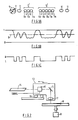
- FIG. 11A An example of the preformat portion in a prior art optical memory medium is diagrammatically shown in Fig. 11A.
- guide grooves 1 formed concentrically or spirally on the surface of a substrate 2 and the information is recorded on said guide grooves 1.
- Prepits 3 having a variety of lengths are formed in alignment with the guide grooves 1.
- a recording layer made of a suitable material is formed by a vacuum deposition, spattering method or spin coating method.
- the substrate is covered by a protective substrate, or a hard coating composition is applied, to obtain an optical memory medium.
- FIG. 11B When the guide grooves 1 and prepits 3 are scanned by a laser spot, signals having the waveform as shown in Fig. 11B are obtained from the reflected light beam. The obtained signals are modulated in accordance with the lengths of the prepits 3. The signals will be demodulated and binary coded by setting an appropriate slice level. It is known that the modulated signals are closely related to the physical structure of the prepits 3.
- Figures 6A and 6B diagrammatically illustrate that the reflected light beam from the optical recording medium is vignetted in an object lens of a reading/recording apparatus, due to the diffraction effect in the pit portions and the unpitted portions. As seen from Figs.
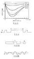
- Figure 13 shows the relation between the pit widths ⁇ which are normalized by the diameter of the light spot (P x 1/e2; the diameter at which the light strength is 1/e2 times of the peak strength) and the signal levels obtained from prepits which are longer than the diameter of the light spot, using the depth ⁇ normalized to the wavelength of the light spot as a parameter.
- the signal levels of the reflected beams are plotted in relation to the signal level obtained from unpitted portions. From Fig. 13, it will be seen that the degree of the deflection or the modulation of the reflected light beam is greatest when the width of the prepits is approximately 0.32 times of the diameter of the light spot. Therefore, the prepits are formed so that their width becomes as close to this value as possible.
- a substrate for an optical memory medium is produced as follows.
- a photoresist is applied to a glass substrate, and the substrate is exposed by scanning a laser beam of a short wavelength such as an Ar laser which is modulated in accordance with a coded signal of the information to be prerecorded.
- the portions exposed to the laser beam are removed by developing, to form prepits or grooves.
- the pattern of the original substrate is transferred to a glass or plastic substrate, to obtain a substrate for an optical memory medium.
- the coded signal has square pulses produced continuously (Fig. 14).
- the control of the width of a prepit which is longer than the diameter of a light spot in producing an original substrate has a great influence on the restraint of the distortion of the reproduced signal in an optical memory medium.
- the structure of a conventional optical memory medium requires the fine control of the exposure conditions in producing the original substrate and also a precise control of accuracy in the transfer process, providing an obstacle to the improvement of the yield.
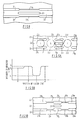
- FIG. 16 Another example of the preformat portion in a prior art optical memory medium is shown in Fig. 16.
- guide grooves 1 are formed on a substrate 4, and a record track 2 is formed between guide grooves 1 adjacent to each other.
- the information such as a track address is prerecorded in the form of prepits 3 formed on the record track 2.
- the width and depth of the guide grooves 1 have a large effect on the track count signal property for a high speed access operation, and on the track servo property for retaining a light spot on the record track 2. Consequently, the width of the guide grooves 1 is set within the range from about 0.3 ⁇ m to about 0.5 ⁇ m.
- the prerecorded information is read out using the diffraction in the prepits 3.
- the reflected light intensity changes as shown in Fig. 17B.
- I1 is the reflected light intensity obtained when the light spot is on the prepits 3
- I2 is the reflected light intensity obtained when the light spot is on a portion other than the prepits 3.
- the information is read out based on the difference between the light intensities I1 and I2. Therefore, the quality of the reproduced signal depends on the degree of the difference between the light intensities I1 and I2.
- the properties of the information signal which is read out from prepits 3 are greatly affected by the width and/or depth of the guide grooves 1.
- the width of the guide grooves 1 is set to be 0.3 ⁇ m to 0.5 ⁇ m as stated above, the diffraction efficiency in the prepits 3 is lowered so that the difference between the light intensities becomes small, resulting in that a reproduced signal of high quality cannot be obtained from the prepits 3.
- the optical memory medium of this invention which overcomes the above-discussed and numerous other disadvantages and deficiencies of the prior art, comprises prepits on which a light spot is impinged to obtain information, wherein each of those among said prepits which are longer than the diameter of the light spot consists of a series of pit portions and unpitted portions.
- the optical memory medium comprises guide grooves and prepits, said guide grooves are formed discontinuously, and each of said prepits is sandwiched between two of the discontinuous portions of guide grooves adjacent to each other.
- the optical memory medium comprises guide grooves and prepits, said guide grooves have one or more narrow portions, and each of said prepits is sandwiched between two of said narrow portions of guide grooves adjacent to each other.
- the narrow portions are longer than the prepit which is sandwiched between said narrow portions.
- the optical memory medium comprises guide grooves and prepits, said guide grooves have one or more long portions, one or more short portions, and unpitted portions formed between said long and short portions, and each of said prepits is sandwiched between two of said short portions of the guide grooves adjacent to each other.
- the optical memory medium comprises guide grooves and prepits, said guide grooves have one or more long portions, one or more short portions, and narrow portions formed between said long and short portions, and each of said prepits is sandwiched between two of said short portions of guide grooves adjacent to each other.
- the present optical memory medium can prevent the reproduced signal from being distorted, so that a signal of high quality can be reproduced.
- the optical memory medium of the invention can surely provide a reproduced signal which is well comparable in quality to that of a conventional medium which has long prepits of an accurately controlled width.
- the signal input into the modulator 15 has been previously processed by a signal processor (not shown) so that the prepits 11′ consist of pit portions 11a and unpitted portions 12. More specifically, the signal which corresponds to the signal C in Fig. 14 is converted into a pulse signal train in which each pulse has a width corresponding to the pit portions 11a and the number of the pulses corresponds to that of the pit portions 11a (Fig. 3).
- the original substrate 18 After being exposed by the apparatus 13, the original substrate 18 is put into developing and etching processes and the exposed portions are etched away so that prepits are formed.
- an optical memory medium preformatted as shown in Fig. 1A can be produced.
- a signal having a waveform which is substantially undistorted can be obtained from the portion corresponding to the prepit 11′.
- Figure 4 shows a result of an experiment which was conducted to simulate the suppression effect of the medium of this example on the distortion of the reproduced signal.
- a laser spot having the diameter of 1.3 ⁇ m was scanned on a conventional optical memory medium having a long prepit which is 2.8 ⁇ m in length, 0.8 ⁇ m in width and ⁇ /4 ( ⁇ is the wavelength of the laser beam) in depth (shown by a broken line in Fig. 14), and also on an optical memory medium according to the invention which has a prepit 11′ comprising three prepit portions 11a having the diameter of 0.8 ⁇ m (shown by solid lines in Fig. 4).
- the prepit portions 11a were arranged in the pitch of 1 ⁇ m.
- the signal level obtained from the conventional medium is shown by a broken line, and that obtained from the present medium by a solid line.
- the signal obtained from the conventional medium was remarkably distorted in the mid portion of the prepit.
- the signal obtained from the present medium was scarcely distorted.
- the adverse effect of the guide grooves 21 on the diffraction of the light beam in the prior art can be greatly reduced. Accordingly, the diffraction of the light beam impinged on the prepit 23 can be generated more effectively as compared to the conventional optical memory medium in which guide grooves are formed also at the both sides of prepits, which results in the high quality reproduced signal having a large amplitude level. Particularly, the quality of the signal obtained from prepits which are longer than the diameter of the light spot can be remarkably improved.
- the prepit 23 is too long, a difficulty may arise. Namely, because the discontinuous portions 21a also becomes long, a light spot which is to be scanned along the guide track 22 may be deviated from the guide track 22 as shown in Fig. 7. Consequently, it may be preferable to employ the arrangement of this example in an optical memory medium having relatively short prepits.
- FIG. 8 A further example of the optical memory medium according to the invention is illustrated in Fig. 8.
- guide grooves 21 have a narrow portion 21b.
- a prepit 23 is formed between two narrow portions 21b of guide grooves 21 which are adjacent to each other.
- the above-mentioned difficulty in Example 2 can be obviated because the portions 21b of the guide grooves 21 are positioned at the both sides of the prepit 23.
- the existence of the narrow portions 21b at the both sides of the prepit 23 slightly lowers the intensity of the reproduced signal, as compared with that obtained from the configuration of Example 2.
- the intensity of the reproduced signal obtained from the optical memory medium of this example is sufficiently great when compared with that obtained from the conventional configuration in which guide grooves have a uniform width.
- the fourth example ( Figure 9A) of the optical memory medium of the invention comprises guide grooves 21 each of which has one or more series of a long portion 21c, a discontinuous portion 21d, a short portion 21e, a discontinuous portion 21f and a long portion 21g.
- a prepit 23 is formed between the short portions 21e of two guide grooves 21 adjacent to each other.
- the reflected light beam obtained from the unpitted regions i.e., the points b and d
- the reflected light beam obtained from the unpitted regions i.e., the points b and d
- the difference in intensity (I2 - I1) between the reflected light beam obtained from the point c at which the prepit 23 is formed and the reflected light beam obtained from the point b or d is great so that a reproduced signal of high quality can be obtained.
- each guide groove 21 has one or more series of a long portion 21h, a narrow portion 21i, a short portion 21j, a narrow portion 21k and a long portion 21m.
- a prepit 23 is formed between the short portions 21j of two guide grooves 21 adjacent to each other.
- the narrow portions 21i and 21k of two guide grooves 21 adjacent to each other are disposed.
- the width of the long and short portions 21h, 21m and 21j is preferably set to the value from 0.3 ⁇ m to 0.5 ⁇ m.
- the width of the narrow portions 21i and 21k is preferably set to 70 % of the width of the long and short portions 21h, 21m and 21j, but is not restricted to it and can be selected from a wide range.
- the intensity of the reflected light beam obtained from the prepit 23 is slightly decreased as compared with that of Example 4, because the narrow portions 21i and 21k of the guide grooves 21 are disposed in front of and in rear of the prepits 23. Because the width of the portions 21i and 21k is small, however, the degree of the decrease is suppressed so that the difference in intensity between the reflected light beam obtained from the prepit 23 and that obtained from the region where no prepit is formed is sufficiently great.
Landscapes
- Optical Recording Or Reproduction (AREA)
Priority Applications (2)
| Application Number | Priority Date | Filing Date | Title |
|---|---|---|---|
| EP92203371A EP0527539B1 (de) | 1987-11-18 | 1988-11-18 | Optisches Speichermedium |
| EP97202025A EP0811969B1 (de) | 1987-11-18 | 1988-11-18 | Optisches Speichermedium |
Applications Claiming Priority (6)
| Application Number | Priority Date | Filing Date | Title |
|---|---|---|---|
| JP62291186A JP2568225B2 (ja) | 1987-11-18 | 1987-11-18 | 光メモリ素子用基板 |
| JP291187/87 | 1987-11-18 | ||
| JP62291187A JPH01133234A (ja) | 1987-11-18 | 1987-11-18 | 光メモリ素子用基板 |
| JP291186/87 | 1987-11-18 | ||
| JP62332647A JP2637445B2 (ja) | 1987-12-25 | 1987-12-25 | 光メモリ素子用基板 |
| JP332647/87 | 1987-12-25 |
Related Child Applications (2)
| Application Number | Title | Priority Date | Filing Date |
|---|---|---|---|
| EP92203371.7 Division-Into | 1988-11-18 | ||
| EP92203371A Division EP0527539B1 (de) | 1987-11-18 | 1988-11-18 | Optisches Speichermedium |
Publications (3)
| Publication Number | Publication Date |
|---|---|
| EP0317344A2 true EP0317344A2 (de) | 1989-05-24 |
| EP0317344A3 EP0317344A3 (en) | 1990-11-28 |
| EP0317344B1 EP0317344B1 (de) | 1994-06-08 |
Family
ID=27337635
Family Applications (3)
| Application Number | Title | Priority Date | Filing Date |
|---|---|---|---|
| EP92203371A Expired - Lifetime EP0527539B1 (de) | 1987-11-18 | 1988-11-18 | Optisches Speichermedium |
| EP88310925A Expired - Lifetime EP0317344B1 (de) | 1987-11-18 | 1988-11-18 | Optisches Speichermedium |
| EP97202025A Expired - Lifetime EP0811969B1 (de) | 1987-11-18 | 1988-11-18 | Optisches Speichermedium |
Family Applications Before (1)
| Application Number | Title | Priority Date | Filing Date |
|---|---|---|---|
| EP92203371A Expired - Lifetime EP0527539B1 (de) | 1987-11-18 | 1988-11-18 | Optisches Speichermedium |
Family Applications After (1)
| Application Number | Title | Priority Date | Filing Date |
|---|---|---|---|
| EP97202025A Expired - Lifetime EP0811969B1 (de) | 1987-11-18 | 1988-11-18 | Optisches Speichermedium |
Country Status (4)
| Country | Link |
|---|---|
| US (2) | US5477524A (de) |
| EP (3) | EP0527539B1 (de) |
| CA (1) | CA1317374C (de) |
| DE (3) | DE3856147T2 (de) |
Cited By (3)
| Publication number | Priority date | Publication date | Assignee | Title |
|---|---|---|---|---|
| EP0718831A3 (de) * | 1994-12-20 | 1997-05-21 | Matsushita Electric Industrial Co Ltd | Aufzeichnungs- und Wiedergabeverfahren eines optischen Informationsaufzeichnungsmediums |
| EP0847046A3 (de) * | 1994-12-20 | 1998-07-01 | Matsushita Electric Industrial Co., Ltd | Veränderliche Beziehung zwischen Signal und Zwischenraum bei einem optischem Aufzeichnungsmedium |
| US5953299A (en) * | 1996-05-30 | 1999-09-14 | Hitachi, Ltd. | Information recording method and apparatus |
Families Citing this family (18)
| Publication number | Priority date | Publication date | Assignee | Title |
|---|---|---|---|---|
| EP0527539B1 (de) * | 1987-11-18 | 1998-03-11 | Sharp Kabushiki Kaisha | Optisches Speichermedium |
| US5796712A (en) * | 1992-03-05 | 1998-08-18 | Fujitsu Limited | Optical disk having identification signal recorded between and used in common for two mutually adjacent tracks and optical disk unit therefor |
| US5638354A (en) * | 1993-07-16 | 1997-06-10 | Ricoh Company, Ltd. | Optical information recording medium |
| JP2658905B2 (ja) * | 1994-10-07 | 1997-09-30 | 日本電気株式会社 | 光ディスクの情報処理方法およびその情報処理装置 |
| US5896365A (en) * | 1995-04-28 | 1999-04-20 | Canon Kabushiki Kaisha | Optical information recording medium capable of recording in lands and grooves without a track-jumping operation; optical information recording/reproducing apparatus using, and master disk exposure apparatus for producing the same |
| JP3081934B2 (ja) * | 1995-08-17 | 2000-08-28 | 富士通株式会社 | 光磁気記録媒体 |
| US6058099A (en) * | 1995-12-29 | 2000-05-02 | Sony Corporation | Disc-shaped information recording medium having offset address information data |
| EP0794509A3 (de) | 1996-03-05 | 1998-08-05 | Canon Kabushiki Kaisha | Informationsaufzeichnungsmedium und Verfahren zu seiner Herstellung |
| JPH10106040A (ja) * | 1996-09-26 | 1998-04-24 | Canon Inc | 光学的情報記録媒体および光学的情報記録再生装置 |
| JPH10198959A (ja) * | 1997-01-10 | 1998-07-31 | Sony Corp | 相変化光ディスクの初期化方法及び相変化光ディスク |
| JP3104222B2 (ja) * | 1997-05-19 | 2000-10-30 | ソニー株式会社 | 光ディスク装置 |
| JPH1173685A (ja) * | 1997-08-29 | 1999-03-16 | Sony Corp | 光記録媒体及びその製造方法 |
| FR2769119B1 (fr) * | 1997-09-26 | 1999-12-03 | Thomson Csf | Disque d'enregistrement anti-piratage, procede de lecture et tete d'enregistrement |
| CN1161769C (zh) | 1998-04-06 | 2004-08-11 | 伊美申公司 | 数据存储盘的反转光学母盘的制造 |
| JP2000011460A (ja) * | 1998-06-22 | 2000-01-14 | Pioneer Electron Corp | 光ディスク |
| JP3520203B2 (ja) * | 1998-07-23 | 2004-04-19 | 太陽誘電株式会社 | 光情報媒体 |
| EP1772863A3 (de) * | 1999-04-08 | 2008-12-24 | Pioneer Corporation | Optisches Aufzeichnungsmedium |
| JP4226204B2 (ja) * | 2000-09-14 | 2009-02-18 | パイオニア株式会社 | 光学式記録媒体、その製造装置および製造方法 |
Family Cites Families (24)
| Publication number | Priority date | Publication date | Assignee | Title |
|---|---|---|---|---|
| DE620301C (de) | 1933-03-09 | 1935-10-18 | Kurt Albert G M B H Chemische | Verfahren zur Herstellung heller Kunstharze |
| US4383311A (en) * | 1980-10-21 | 1983-05-10 | Rca Corporation | Optical recording medium and information record with indented overcoat |
| FR2504301A1 (fr) * | 1981-04-15 | 1982-10-22 | Thomson Csf | Support d'informations mobile et dispositif d'enregistrement-lecture comprenant un tel support |
| JPS57208647A (en) * | 1981-06-18 | 1982-12-21 | Toshiba Corp | Optical disk for recording of information |
| US4443870A (en) * | 1981-10-15 | 1984-04-17 | Burroughs Corporation | Optical memory system providing track following |
| JPS60157740A (ja) * | 1984-01-27 | 1985-08-19 | Ricoh Co Ltd | 光デイスク |
| JPS60261043A (ja) * | 1984-06-07 | 1985-12-24 | Victor Co Of Japan Ltd | 情報記録媒体円盤 |
| JPS6163930A (ja) * | 1984-09-04 | 1986-04-02 | Matsushita Electric Ind Co Ltd | 円盤状記録担体及び円盤状記録担体のアドレス信号再生装置 |
| JPS6185653A (ja) * | 1984-10-02 | 1986-05-01 | Sharp Corp | 光磁気メモリ素子 |
| JP2559362B2 (ja) * | 1985-03-22 | 1996-12-04 | 株式会社日立製作所 | 光学的記録方法 |
| US4646103A (en) * | 1985-03-20 | 1987-02-24 | Hitachi, Ltd. | Optical recording method |
| JPH06103539B2 (ja) * | 1985-12-06 | 1994-12-14 | 株式会社日立製作所 | 光デイスクトラツキング装置 |
| US4748609A (en) * | 1985-03-29 | 1988-05-31 | Hitachi, Ltd. | Method and apparatus for composite tracking servo system with track offset correction and rotary optical disc having at least one correction mark for correcting track offset |
| FR2581784B1 (fr) * | 1985-05-10 | 1994-03-25 | Thomson Alcatel Gigadisc | Support d'information a pregravure et son dispositif de lecture optique |
| NL193159C (nl) * | 1985-06-19 | 1998-12-04 | Hitachi Ltd | Voorgevormde registratiedrager voor het daarin met behulp van een lichtvlek schrijven van informatie. |
| JPS62110637A (ja) * | 1985-11-08 | 1987-05-21 | Matsushita Electric Ind Co Ltd | 情報記録担体 |
| JP2644214B2 (ja) * | 1985-11-20 | 1997-08-25 | シャープ株式会社 | 光メモリ基板 |
| JPS62229576A (ja) * | 1986-03-31 | 1987-10-08 | Canon Inc | 情報記録媒体のプリフオ−マツト形式 |
| US4910725A (en) * | 1986-04-23 | 1990-03-20 | Drexler Technology Corporation | Optical recording method for data cards |
| JPS6344332A (ja) * | 1986-08-11 | 1988-02-25 | Hitachi Maxell Ltd | 光デイスクおよびその製造方法 |
| JP2548186B2 (ja) * | 1987-04-13 | 1996-10-30 | パイオニア株式会社 | 案内溝付光デイスク |
| JPS6450247A (en) * | 1987-08-20 | 1989-02-27 | Fujitsu General Ltd | Optical disk recording and reproducing device |
| EP0527539B1 (de) * | 1987-11-18 | 1998-03-11 | Sharp Kabushiki Kaisha | Optisches Speichermedium |
| US5268887A (en) * | 1990-05-15 | 1993-12-07 | Kabushiki Kaisha Toshiba | Optical recording medium having offset-compensating areas |
-
1988
- 1988-11-18 EP EP92203371A patent/EP0527539B1/de not_active Expired - Lifetime
- 1988-11-18 CA CA000583549A patent/CA1317374C/en not_active Expired - Fee Related
- 1988-11-18 DE DE3856147T patent/DE3856147T2/de not_active Expired - Lifetime
- 1988-11-18 EP EP88310925A patent/EP0317344B1/de not_active Expired - Lifetime
- 1988-11-18 EP EP97202025A patent/EP0811969B1/de not_active Expired - Lifetime
- 1988-11-18 DE DE3856572T patent/DE3856572T2/de not_active Expired - Lifetime
- 1988-11-18 DE DE3850050T patent/DE3850050T2/de not_active Expired - Lifetime
-
1994
- 1994-09-13 US US08/304,810 patent/US5477524A/en not_active Expired - Lifetime
-
1995
- 1995-09-27 US US08/534,300 patent/US5754523A/en not_active Expired - Fee Related
Cited By (17)
| Publication number | Priority date | Publication date | Assignee | Title |
|---|---|---|---|---|
| US6487151B1 (en) | 1994-12-20 | 2002-11-26 | Matsushita Electric Industrial Co. Ltd. | Optical information recording and reproducing system with overwrite capability and recording medium for use therewith |
| EP0847046A3 (de) * | 1994-12-20 | 1998-07-01 | Matsushita Electric Industrial Co., Ltd | Veränderliche Beziehung zwischen Signal und Zwischenraum bei einem optischem Aufzeichnungsmedium |
| EP0843305A3 (de) * | 1994-12-20 | 1998-07-01 | Matsushita Electric Industrial Co., Ltd | Optisches Aufzeichnungsverfahren mit variierter Lichtintensität |
| US6707776B2 (en) | 1994-12-20 | 2004-03-16 | Matsushita Electric Industrial Co., Ltd. | Recording and reproducing method of optical information recording medium |
| US6031814A (en) * | 1994-12-20 | 2000-02-29 | Matsushita Electric Industrial Co., Ltd. | Optical disk with stop-pulse generating means in a guide groove |
| US6697313B2 (en) | 1994-12-20 | 2004-02-24 | Matsushita Electric Industrial Co., Ltd. | Optical information recording and reproducing system with overwrite capability and recording medium for use therewith |
| EP0718831A3 (de) * | 1994-12-20 | 1997-05-21 | Matsushita Electric Industrial Co Ltd | Aufzeichnungs- und Wiedergabeverfahren eines optischen Informationsaufzeichnungsmediums |
| US6683739B2 (en) | 1994-12-20 | 2004-01-27 | Matsushita Electric Industrial Co., Ltd. | Optical information recording and reproducing system with overwrite capability and recording medium for use therewith |
| US6580673B2 (en) | 1996-05-30 | 2003-06-17 | Hitachi, Ltd. | Information recording method and apparatus |
| US6430134B1 (en) | 1996-05-30 | 2002-08-06 | Hitachi, Ltd. | Information recording method and apparatus |
| US6307825B1 (en) | 1996-05-30 | 2001-10-23 | Hitachi, Ltd. | Information recording method and apparatus |
| US6181661B1 (en) | 1996-05-30 | 2001-01-30 | Hitachi, Ltd. | Information recording method and apparatus |
| US5953299A (en) * | 1996-05-30 | 1999-09-14 | Hitachi, Ltd. | Information recording method and apparatus |
| US6788643B2 (en) | 1996-05-30 | 2004-09-07 | Hitachi, Ltd. | Information recording method and apparatus |
| US7075884B2 (en) | 1996-05-30 | 2006-07-11 | Hitachi, Ltd. | Optical recording apparatus capable of changing the length of synchronization portions |
| US7092348B2 (en) | 1996-05-30 | 2006-08-15 | Hitachi, Ltd. | Optical recording apparatus capable of changing the length of synchronization portions |
| US7099262B2 (en) | 1996-05-30 | 2006-08-29 | Hitachi, Ltd. | Rewritable recording medium capable of changing the length and start position of synchronization portion |
Also Published As
| Publication number | Publication date |
|---|---|
| EP0527539A3 (en) | 1993-11-10 |
| DE3856572T2 (de) | 2005-09-22 |
| DE3850050D1 (de) | 1994-07-14 |
| EP0317344A3 (en) | 1990-11-28 |
| US5754523A (en) | 1998-05-19 |
| DE3856572D1 (de) | 2004-10-21 |
| EP0811969B1 (de) | 2004-09-15 |
| EP0811969A2 (de) | 1997-12-10 |
| EP0527539B1 (de) | 1998-03-11 |
| EP0317344B1 (de) | 1994-06-08 |
| DE3856147D1 (de) | 1998-04-16 |
| EP0811969A3 (de) | 2000-12-06 |
| EP0527539A2 (de) | 1993-02-17 |
| CA1317374C (en) | 1993-05-04 |
| DE3850050T2 (de) | 1994-09-22 |
| DE3856147T2 (de) | 1998-09-17 |
| US5477524A (en) | 1995-12-19 |
Similar Documents
| Publication | Publication Date | Title |
|---|---|---|
| EP0317344B1 (de) | Optisches Speichermedium | |
| EP0144436B1 (de) | Optische aufzeichnungs- und wiedergabevorrichtung | |
| JP2663817B2 (ja) | 光ディスク及びそれを用いた光ディスク装置 | |
| US6487147B2 (en) | Optical information recording medium and an optical information recording/reproduction device | |
| GB2250626A (en) | An optical information recording substrate and method of making thereof | |
| EP0311372A2 (de) | Optisches Gerät für optisches Informationsaufzeichnungsmedium | |
| US6667949B2 (en) | Optical record carrier and scanning device | |
| EP0896325B1 (de) | Optische Platte mit hoher Schreibdichte, Wiedergabegerät für optische Platte, und Verfahren zur Herstellung einer Matrize für optische Platten | |
| US4949330A (en) | Apparatus for pre-forming servo-track portions and sector addresses having the same predetermined width | |
| EP0480125A1 (de) | Optischer Datenträger mit Phasenwechselaufzeichnung | |
| JP3227976B2 (ja) | 光学的情報記録部材、記録再生方法、及び記録再生装置 | |
| US5517485A (en) | Optical information recording medium having first and second tracks and apparatus for recording to and reproducing from the medium | |
| US4759006A (en) | Abnormal track skipping detection and control arrangement | |
| GB2277827A (en) | Making an optical information record substrate | |
| JP3374086B2 (ja) | 光磁気記録媒体 | |
| HK1040135A1 (en) | Recording medium and apparatus and method for manufacturing the same | |
| US5654953A (en) | Optical disk and method of manufacturing the same | |
| EP1772862B1 (de) | Verfahrung zur Herstellung eines optischen Aufzeichnungsmediums und optisches Aufzeichnungsmedium | |
| KR0136908B1 (ko) | 기록 캐리어 및 광학 기록 캐리어 판독장치 | |
| JP2568225B2 (ja) | 光メモリ素子用基板 | |
| JPH1173685A (ja) | 光記録媒体及びその製造方法 | |
| JP2713974B2 (ja) | ディスク | |
| JP2743920B2 (ja) | ディスク | |
| JP3908925B2 (ja) | 光学的情報記録再生方法、光学的情報記録再生装置 | |
| JPH0896363A (ja) | 光情報記録媒体のフォーマット形成方法 |
Legal Events
| Date | Code | Title | Description |
|---|---|---|---|
| PUAI | Public reference made under article 153(3) epc to a published international application that has entered the european phase |
Free format text: ORIGINAL CODE: 0009012 |
|
| 17P | Request for examination filed |
Effective date: 19881126 |
|
| AK | Designated contracting states |
Kind code of ref document: A2 Designated state(s): DE FR GB IT NL |
|
| PUAL | Search report despatched |
Free format text: ORIGINAL CODE: 0009013 |
|
| AK | Designated contracting states |
Kind code of ref document: A3 Designated state(s): DE FR GB IT NL |
|
| 17Q | First examination report despatched |
Effective date: 19920708 |
|
| GRAA | (expected) grant |
Free format text: ORIGINAL CODE: 0009210 |
|
| AK | Designated contracting states |
Kind code of ref document: B1 Designated state(s): DE FR GB IT NL |
|
| ITF | It: translation for a ep patent filed | ||
| REF | Corresponds to: |
Ref document number: 3850050 Country of ref document: DE Date of ref document: 19940714 |
|
| ET | Fr: translation filed | ||
| PLBE | No opposition filed within time limit |
Free format text: ORIGINAL CODE: 0009261 |
|
| STAA | Information on the status of an ep patent application or granted ep patent |
Free format text: STATUS: NO OPPOSITION FILED WITHIN TIME LIMIT |
|
| 26N | No opposition filed | ||
| PGFP | Annual fee paid to national office [announced via postgrant information from national office to epo] |
Ref country code: NL Payment date: 19971130 Year of fee payment: 10 |
|
| PG25 | Lapsed in a contracting state [announced via postgrant information from national office to epo] |
Ref country code: NL Free format text: LAPSE BECAUSE OF NON-PAYMENT OF DUE FEES Effective date: 19990601 |
|
| NLV4 | Nl: lapsed or anulled due to non-payment of the annual fee |
Effective date: 19990601 |
|
| REG | Reference to a national code |
Ref country code: GB Ref legal event code: IF02 |
|
| PG25 | Lapsed in a contracting state [announced via postgrant information from national office to epo] |
Ref country code: IT Free format text: LAPSE BECAUSE OF NON-PAYMENT OF DUE FEES Effective date: 20051118 |
|
| PGFP | Annual fee paid to national office [announced via postgrant information from national office to epo] |
Ref country code: DE Payment date: 20071115 Year of fee payment: 20 |
|
| PGFP | Annual fee paid to national office [announced via postgrant information from national office to epo] |
Ref country code: GB Payment date: 20071114 Year of fee payment: 20 Ref country code: FR Payment date: 20071108 Year of fee payment: 20 |
|
| REG | Reference to a national code |
Ref country code: GB Ref legal event code: PE20 Expiry date: 20081117 |
|
| PG25 | Lapsed in a contracting state [announced via postgrant information from national office to epo] |
Ref country code: GB Free format text: LAPSE BECAUSE OF EXPIRATION OF PROTECTION Effective date: 20081117 |