EP0317643A1 - Procede de production d'un supraconducteur a base d'oxyde - Google Patents
Procede de production d'un supraconducteur a base d'oxyde Download PDFInfo
- Publication number
- EP0317643A1 EP0317643A1 EP88905217A EP88905217A EP0317643A1 EP 0317643 A1 EP0317643 A1 EP 0317643A1 EP 88905217 A EP88905217 A EP 88905217A EP 88905217 A EP88905217 A EP 88905217A EP 0317643 A1 EP0317643 A1 EP 0317643A1
- Authority
- EP
- European Patent Office
- Prior art keywords
- powder
- oxide superconductor
- oxide
- superconductor
- mixed powder
- Prior art date
- Legal status (The legal status is an assumption and is not a legal conclusion. Google has not performed a legal analysis and makes no representation as to the accuracy of the status listed.)
- Granted
Links
Images




Classifications
-
- C—CHEMISTRY; METALLURGY
- C01—INORGANIC CHEMISTRY
- C01B—NON-METALLIC ELEMENTS; COMPOUNDS THEREOF; METALLOIDS OR COMPOUNDS THEREOF NOT COVERED BY SUBCLASS C01C
- C01B13/00—Oxygen; Ozone; Oxides or hydroxides in general
- C01B13/14—Methods for preparing oxides or hydroxides in general
- C01B13/18—Methods for preparing oxides or hydroxides in general by thermal decomposition of compounds, e.g. of salts or hydroxides
-
- B—PERFORMING OPERATIONS; TRANSPORTING
- B03—SEPARATION OF SOLID MATERIALS USING LIQUIDS OR USING PNEUMATIC TABLES OR JIGS; MAGNETIC OR ELECTROSTATIC SEPARATION OF SOLID MATERIALS FROM SOLID MATERIALS OR FLUIDS; SEPARATION BY HIGH-VOLTAGE ELECTRIC FIELDS
- B03C—MAGNETIC OR ELECTROSTATIC SEPARATION OF SOLID MATERIALS FROM SOLID MATERIALS OR FLUIDS; SEPARATION BY HIGH-VOLTAGE ELECTRIC FIELDS
- B03C1/00—Magnetic separation
- B03C1/02—Magnetic separation acting directly on the substance being separated
- B03C1/021—Separation using Meissner effect, i.e. deflection of superconductive particles in a magnetic field
-
- C—CHEMISTRY; METALLURGY
- C01—INORGANIC CHEMISTRY
- C01B—NON-METALLIC ELEMENTS; COMPOUNDS THEREOF; METALLOIDS OR COMPOUNDS THEREOF NOT COVERED BY SUBCLASS C01C
- C01B13/00—Oxygen; Ozone; Oxides or hydroxides in general
- C01B13/14—Methods for preparing oxides or hydroxides in general
- C01B13/16—Purification
-
- C—CHEMISTRY; METALLURGY
- C01—INORGANIC CHEMISTRY
- C01G—COMPOUNDS CONTAINING METALS NOT COVERED BY SUBCLASSES C01D OR C01F
- C01G3/00—Compounds of copper
- C01G3/006—Compounds containing copper, with or without oxygen or hydrogen, and containing two or more other elements
-
- C—CHEMISTRY; METALLURGY
- C04—CEMENTS; CONCRETE; ARTIFICIAL STONE; CERAMICS; REFRACTORIES
- C04B—LIME, MAGNESIA; SLAG; CEMENTS; COMPOSITIONS THEREOF, e.g. MORTARS, CONCRETE OR LIKE BUILDING MATERIALS; ARTIFICIAL STONE; CERAMICS; REFRACTORIES; TREATMENT OF NATURAL STONE
- C04B35/00—Shaped ceramic products characterised by their composition; Ceramics compositions; Processing powders of inorganic compounds preparatory to the manufacturing of ceramic products
- C04B35/01—Shaped ceramic products characterised by their composition; Ceramics compositions; Processing powders of inorganic compounds preparatory to the manufacturing of ceramic products based on oxide ceramics
- C04B35/45—Shaped ceramic products characterised by their composition; Ceramics compositions; Processing powders of inorganic compounds preparatory to the manufacturing of ceramic products based on oxide ceramics based on copper oxide or solid solutions thereof with other oxides
-
- H—ELECTRICITY
- H10—SEMICONDUCTOR DEVICES; ELECTRIC SOLID-STATE DEVICES NOT OTHERWISE PROVIDED FOR
- H10N—ELECTRIC SOLID-STATE DEVICES NOT OTHERWISE PROVIDED FOR
- H10N60/00—Superconducting devices
- H10N60/01—Manufacture or treatment
- H10N60/0268—Manufacture or treatment of devices comprising copper oxide
-
- C—CHEMISTRY; METALLURGY
- C01—INORGANIC CHEMISTRY
- C01P—INDEXING SCHEME RELATING TO STRUCTURAL AND PHYSICAL ASPECTS OF SOLID INORGANIC COMPOUNDS
- C01P2004/00—Particle morphology
- C01P2004/60—Particles characterised by their size
- C01P2004/61—Micrometer sized, i.e. from 1-100 micrometer
-
- C—CHEMISTRY; METALLURGY
- C01—INORGANIC CHEMISTRY
- C01P—INDEXING SCHEME RELATING TO STRUCTURAL AND PHYSICAL ASPECTS OF SOLID INORGANIC COMPOUNDS
- C01P2006/00—Physical properties of inorganic compounds
- C01P2006/40—Electric properties
-
- Y—GENERAL TAGGING OF NEW TECHNOLOGICAL DEVELOPMENTS; GENERAL TAGGING OF CROSS-SECTIONAL TECHNOLOGIES SPANNING OVER SEVERAL SECTIONS OF THE IPC; TECHNICAL SUBJECTS COVERED BY FORMER USPC CROSS-REFERENCE ART COLLECTIONS [XRACs] AND DIGESTS
- Y10—TECHNICAL SUBJECTS COVERED BY FORMER USPC
- Y10S—TECHNICAL SUBJECTS COVERED BY FORMER USPC CROSS-REFERENCE ART COLLECTIONS [XRACs] AND DIGESTS
- Y10S505/00—Superconductor technology: apparatus, material, process
- Y10S505/825—Apparatus per se, device per se, or process of making or operating same
- Y10S505/931—Classifying, separating, and assorting solids using magnetism
- Y10S505/932—Separating diverse particulates
Definitions
- This invention relates to a method for manufacturing an oxide superconductor and more particularly to a novel method for separating superconductor powder.
- Fig. 1 is an explanatory view showing the conventional method for manufacturing an oxide superconductor disclosed for example in a paper entitled “Manufacture and Evaluation of Ceramics High-Temperature Superconducting Material", Koji Kishidera, Industrial Chemical Engineering, Department of Engineering, Tokyo University published at a symposium entitled “Manufacture and Application of High-Temperature Superconducting Material” on April 6, 1987.
- an oxide of lanthanoid metal and alkaline earth metal and an oxide of copper are weighting (1)
- the second step is mixing (2) in a mortar
- the third step is prebaking (3) at a temperature of several hundred degrees
- the fourth step is crushing and mixing (4)
- the fifth step is shaping (5) into a desired configuration
- the sixth step is final baking at a temperature of from 900 °C to 1100 °C.
- This method is the one called the powder mixing method, and one example of the characteristics of the resistance relative to temperature of an oxide superconductor manufactured by this method is illustrated in a characteristic curve I in Fig. 2.
- the axis of ordinate represents temperature and the axis of abscisa represents resistance.
- the point E is the temperature usually referred to as an onset at which the change in resistance begines'to rapidly decrease, and the point F is the temperature usually referred to as an offset at which the resistance disappears.
- the change in resistance according to temperature of the oxide superconductor manufactured by the conventional manufacturing method is as shown by the characteristic curve I, from which it is seen that the temperature difference between the point E of the onset and the point F of the offset is large, making the offset or the temperature at which the resistance disappears low, so that the necessary low temperature becomes lower and the characteristics as a superconductor is inferior which poses a problem.
- This invention has been made in order to solve the above-discussed problem and has as its object the provision of a method for manufacturing an oxide superconductor which has a high offset temperature and a large temperature difference between the onset and the offset.
- the method for manufacturing an oxide superconductor of the present invention comprises the step of mixing and baking a plurality of different kinds of ingredient material at a predetermined proportion and obtaining a mixed powder having an oxide superconducting powder as a main ingredient, and a step of placing a magnet close to said mixed powder to separate said oxide superconducting powder through the utilization of the magnetic repulsive force due to the Meissner effect of the superconductor.
- the separating step according to the present invention can remove the ingredients which exhibit no superconductivity out of the mixted powder, so that a high-quality oxide superconductor in which the temperature difference between the onset and the offset is small and the offset temperature is high can be obtained.
- Fig. 1 is an explanatory view showing the conventional method for manufacturing an oxide superconductor
- Fig. 2 is a graph showing the resistance-temperature characteristics of the oxide superconductors manufactured by the conventional method and one embodiment of the present invention
- Fig. 3 is an explanatory view showing the method for manufacturing an oxide superconductor according, to one embodiment of the present invention
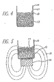
- Fig. 4 is a sectional view schematically showing the state of the mixed powder contained in a container
- Fig. 5 is a schematic diagram illustrating the separating step in one embodiment of the present invention
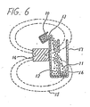
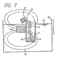
- Figs. 6, 7, 8 and 9 are schematic diagrams illustrating the separating steps in other different embodiments
- Fig. 10 is a characteristic diagram showing the currentcarrying characteristic of the oxide superconductor obtained by the embodiments shown in Figs. 7, 8 and 9.
- Fig. 3 is an explanatory view showing the method for manufacturing the oxide superconductor according to one embodiment of the present invention, in which, while the first to fourth steps .are identical to those in the conventional manufacturing method shown in Fig. 1, the fifth step is the separation (7) of the powder, the sixth step is shaping (8) and the seventh step is final baking (9).
- Fig. 4 (10) is a container, (11) is oxide superconductor powder, (12) is powder exhibiting no superconductivity, (13) is a mixed powder, and in Fig. 5, (14) is a magnet and (15) are lines of magnetic force produced by the magnet (14).
- the mixed powder (13) within the container (10) is a mixture of the powder (11) exhibiting the superconductivity and the powder (12) exhibiting no superconductivity as shown in Fig. 4, and the powder advances to the shaping step (8) which is the subsequent manufacturing step according to the conventional method.
- the magnet (14) is installed at the bottom of the container (10) as shown in Fig. 5, for example.
- the lines of magnetic force (15) extend around the container (10) as shown in the figure.
- the mixed powder (13) is moved and the superconductive powder (11) is moved away from the magnet (14) because it reflects the lines of magnetic force by the magnetic repulsive force due to the diamagnetism action or the Meissner effect. That is, the superconductive powder (11) is collected at the upper portion of the container (10) and the non- superconductive powder (12) collects at the lower portion of the container (10).
- the powder is supplied to the next step.
- the resistance -characteristics against temperature of the oxide superconductor manufactured by the above-described manufacturing method is as shown in a characteristic curve II of Fig. 2, wherein the temperature at the offset point G is high and the temperature difference between the onset point E and the offset point G is small.
- Fig. 6 illustrates an embodiment in which the magnet (14) is disposed on one side of a separating container (17) having a central partition (16) inserted therein and in which the mixed powder (13) is dropped from above the separating container (17). At this time, the superconducting powder (11) moves away from the magnet (14) to fall on the remote side of the partition (16) of the separating container (17). On the other hand, the powder (12) which exhibits no superconductivity freely falls, so that the separation can be carried out. : The separation of the powder is carried out by cooling the oxide superconductive powder to a temperature at which it exhibits superconductivity.
- the method comprises the step of mixing and baking a plurality of different kinds of ingredient material at a predetermined proportion and obtaining a mixed powder having an oxide superconducting powder as a main ingredient, and the step of placing a magnet close to said mixed powder to separate said oxide superconducting powder through the utilization. of the magnetic repulsive force due to the Meissner effect of the superconductor, so that a high-quality oxide superconductor in which the temperature difference between the onset and the offset is small and the offset temperature is high can be obtained.
- Fig. 7 is a container for containing a buoyancy medium (21) such as liquid nitrogen, and x is the falling distance of the powder falling from the container (10) at an initial speed of 0.
- a buoyancy medium (21) such as liquid nitrogen
- the mixed powder (13) within the container (10), which has mixed therein the oxide superconducting powder (11) and the impurity (12) which exhibit no superconductivity, has a particle size usually ranging from 1 ⁇ m to 1 mm. If the particle size is too large, it is possible that both the oxide superconducting powder (11) and the impurity (12) are included in a single particle or grain, so that the particle size must be made relatively small to a certain extent.
- the density of Y-Ba-Cu-0 which is a typical example of the ' oxide superconductor (11) is normally in the order of about 5 : 1 kg/l at 1 atmospheric pressure.
- the density of the liquid nitrogen (21) is 0.8 kg/l.
- Fig. 8 is a sectional view for explaning the separating step of a still another embodiment, in which the arrangement is such that a magnet (23) having a through hole (22) at its center is installed in a slanted position in the buoyancy medium (21), the impurity (12) falls downward through the through hole (22), and the falling path of the oxide superconductor (11) is bent right-downwardly in the figure by the repulsion against the magnet (23) by the Meissner effect.
- the buoyancy medium (21) may be liquid oxygen, liquid air, etc. in addition to liquid nitrogen used in the above embodiments, these medium also serving as a cooling medium for cooling the oxide superconducting powder (11) to be separated below the critical temperature.
- the separated oxide superconducting powder (11) is shaped (8) and finally baked (9) in the above embodiments, it may also be used in the powder state.
- a method which comprises the step of mixing and baking a plurality of different kinds of ingredient material at a predetermined proportion and obtaining a mixed powder having oxide superconducting powder as a main ingredient, and the step of placing a magnet close to said mixed powder to separate said oxide superconducting powder through the utilization of the magnetic repulsive force due to the Meissner effect of the superconductor, said separating step is carried out in a buoyancy medium, so that the separation accuracy is increased and an oxide superconductor having a current-carrying characteristic as shown by a curve II in Fig. 10 which is superior to the oxide superconductor obtained by the method shown in Fig. 6 can be obtained.
- Fig. 10 is a schematic sectional view for explaining one part of the method for manufacturing an oxide superconductor according to this embodiment, wherein (24) is a shieve or a filter A having a mesh size of 100 ⁇ m, (25) is a shieve or a filter B having a mesh size of 1 ⁇ m, (26) is a chamber C, (27) is a chamber D , (28) is a chamber E and (29) is a chamber F.
- the mixed powder (13) within the container (10), which has mixed therein the superconducting powder (11) which is a component exhibiting the superconductivity and the impurity powder (12) which is a component exhibiting no superconductivity, has a particle size usually ranging from less than 0.1 ⁇ m to about 1 mm.
- the mixed powder (13) is separated into the powder having a particle size of equal to or more than 100 ⁇ m and the powder having a particle size of equal to or less than 100 ⁇ m by the filter A (24) of 100 wm mesh.
- the powder of equal to or more than 100 ⁇ m particle size does not pass through the filter A (24) and fall into the right-hand chamber C (26), and the powder of equal to or less than 100 ⁇ m particle size falls through the filter A (24).
- the powder of equal to or less than 100 ⁇ m particle size falls through the filter A (24).
- the powder (11) which is the component exhibiting the superconductivity is pushed to the right in the figure and falls onto the filter B (25).
- the filter B (25) has the mesh size of 1 ⁇ m
- the powder of a particle size - less than 1 ⁇ m falls into the chamber E (28) and the powder of a particle size equal to or more than 1 ⁇ m falls into the chamber D (27), then they are collected and advanced to the next shaping and baking steps. Since the oxide superconductor is manufactured with the powder of uniform particle size, the oxide superconductor having a dense system can be obtained.
- One of the factors for increasing the critical current density and the critical magnetic field of the superconducting-wire is the magnitude of the pinning force, which pinning force depends on the mean particle size of the oxide superconductor and is generally selected to be equal to or greater than 1 ⁇ m as described in a. paper ("Superconducting Magnet Research Center Report" Vol. 3, P.34 - P.38, December, 1986, published from Superconductive Magnet Research Center attached to Department of Engineering, Kyushu University). Also, according to the results of the experiments conducted by the inventors of the present invention, the upper limit is 100 um, and it was confirmed that, if the particle size is larger than this, the oxide superconductor becomes to be poor and has a very wide temperature difference between the onset and the offset.
- the current-carrying characteristic of the oxide superconductor obtained by the above embodiment is shown by the characteristic curve II of Fig. 10. It is seen that the critical current level is at the point B which is significantly high as compared to the point A in case of the previous embodiment shown in Fig. 6.
- the method comprises a step of mixing and baking a plurality of different kinds of ingredient material at a predetermined proportion and obtaining a mixed powder having oxide superconducting powder as a main ingredient, a step of placing a magnet close to said mixed powder to separate said oxide superconducting powder through the utilization of the magnetic repulsive force due to the Meissner effect of the superconductor, and a step of unifying the particle size of said oxide superconductive powder to be from 1 - 100 Jim, so that an oxide superconductor having a high critical current value and superior characteristics can be obtained.
- This invention can be utilized in manufacturing' an oxide superconductor of a high critical current value and improved characteristics.
Landscapes
- Chemical & Material Sciences (AREA)
- Organic Chemistry (AREA)
- Engineering & Computer Science (AREA)
- Inorganic Chemistry (AREA)
- Manufacturing & Machinery (AREA)
- Ceramic Engineering (AREA)
- Materials Engineering (AREA)
- Structural Engineering (AREA)
- Inorganic Compounds Of Heavy Metals (AREA)
- Superconductors And Manufacturing Methods Therefor (AREA)
- Superconductor Devices And Manufacturing Methods Thereof (AREA)
Abstract
Applications Claiming Priority (6)
| Application Number | Priority Date | Filing Date | Title |
|---|---|---|---|
| JP62144401A JPH0662329B2 (ja) | 1987-06-09 | 1987-06-09 | 酸化物超電導体の製造方法 |
| JP144401/87 | 1987-06-09 | ||
| JP205524/87 | 1987-08-18 | ||
| JP62205524A JPS6451306A (en) | 1987-08-18 | 1987-08-18 | Production of oxide superconductor |
| JP221713/87 | 1987-09-03 | ||
| JP62221713A JPH0714494B2 (ja) | 1987-09-03 | 1987-09-03 | 酸化物超電導体の製造方法 |
Publications (3)
| Publication Number | Publication Date |
|---|---|
| EP0317643A1 true EP0317643A1 (fr) | 1989-05-31 |
| EP0317643A4 EP0317643A4 (fr) | 1990-06-05 |
| EP0317643B1 EP0317643B1 (fr) | 1993-05-12 |
Family
ID=27318816
Family Applications (1)
| Application Number | Title | Priority Date | Filing Date |
|---|---|---|---|
| EP88905217A Expired - Lifetime EP0317643B1 (fr) | 1987-06-09 | 1988-06-08 | Procede de production d'un supraconducteur a base d'oxyde |
Country Status (4)
| Country | Link |
|---|---|
| US (1) | US5268353A (fr) |
| EP (1) | EP0317643B1 (fr) |
| DE (1) | DE3880973T2 (fr) |
| WO (1) | WO1988009768A1 (fr) |
Families Citing this family (3)
| Publication number | Priority date | Publication date | Assignee | Title |
|---|---|---|---|---|
| DE19804878A1 (de) * | 1998-02-09 | 1999-08-12 | Exner Hubertus | Verfahren und Vorrichtung zur Trennung von unterschiedlich elektrisch leitfähigen Partikeln |
| US5919737A (en) * | 1998-04-21 | 1999-07-06 | Broide; Efim | Method of separating a superconducting fraction from a mixture |
| EP2679310A4 (fr) * | 2011-02-23 | 2016-05-18 | Ube Industries | Procédé et appareil de séparation d'un mélange |
Family Cites Families (9)
| Publication number | Priority date | Publication date | Assignee | Title |
|---|---|---|---|---|
| SU865392A2 (ru) * | 1976-04-09 | 1981-09-25 | Днепропетровский Ордена Трудового Красного Знамени Горный Институт Им.Артема | Электродинамический сепаратор |
| US4743364A (en) * | 1984-03-16 | 1988-05-10 | Kyrazis Demos T | Magnetic separation of electrically conducting particles from non-conducting material |
| JPS63252553A (ja) * | 1987-04-10 | 1988-10-19 | Canon Inc | 超導電体微粒子の分級方法 |
| HUT47761A (en) * | 1987-04-27 | 1989-03-28 | Mta Koezponti Fiz Kutato Intez | Method and apparatus for improving the quality of superconducting substances with the method of variable temperature magnetic separation |
| JPS63278568A (ja) * | 1987-05-08 | 1988-11-16 | Hitachi Ltd | 超電導物質の選別方法 |
| US4828685A (en) * | 1987-06-24 | 1989-05-09 | General Atomics | Method and apparatus for the enhancement of superconductive materials |
| JPS6428264A (en) * | 1987-07-21 | 1989-01-30 | Sumitomo Electric Industries | Production of superconducting material |
| JPS6430659A (en) * | 1987-07-24 | 1989-02-01 | Sumitomo Heavy Industries | Screening method for superconductive material |
| JP2656550B2 (ja) * | 1987-12-09 | 1997-09-24 | キヤノン株式会社 | 超電導体微粒子の精製装置 |
-
1988
- 1988-06-08 US US07/315,788 patent/US5268353A/en not_active Expired - Fee Related
- 1988-06-08 EP EP88905217A patent/EP0317643B1/fr not_active Expired - Lifetime
- 1988-06-08 DE DE88905217T patent/DE3880973T2/de not_active Expired - Fee Related
- 1988-06-08 WO PCT/JP1988/000549 patent/WO1988009768A1/fr not_active Ceased
Also Published As
| Publication number | Publication date |
|---|---|
| EP0317643B1 (fr) | 1993-05-12 |
| US5268353A (en) | 1993-12-07 |
| DE3880973D1 (de) | 1993-06-17 |
| WO1988009768A1 (fr) | 1988-12-15 |
| DE3880973T2 (de) | 1994-01-27 |
| EP0317643A4 (fr) | 1990-06-05 |
Similar Documents
| Publication | Publication Date | Title |
|---|---|---|
| EP0296477B1 (fr) | Fil supraconducteur | |
| EP0330305B1 (fr) | Oxyde supraconducteur à haute température | |
| EP0303249B1 (fr) | Méthode de fabrication d'un oxyde supraconducteur et méthode de fabrication d'une poudre d'oxyde composite qui est le précurseur de cet oxyde supraconducteur | |
| CA1340229C (fr) | Supraconducteur a base d'oxyde de bismuth; dispositifs et systemes comportant un conducteur de ce type | |
| EP0317643B1 (fr) | Procede de production d'un supraconducteur a base d'oxyde | |
| EP0330214A2 (fr) | Supraconducteur à haute température Tc en oxyde et son procédé de fabrication | |
| EP0285169A2 (fr) | Supra-conducteur et procédé pour sa fabrication | |
| EP0300353B1 (fr) | Méthode de fabrication de supraconducteurs | |
| JPH0312940B2 (fr) | ||
| US5389603A (en) | Oxide superconductors, and devices and systems comprising such a superconductor | |
| EP0564279B1 (fr) | Corps supraconducteur des terres rares et procédé de sa fabrication | |
| EP0456182A2 (fr) | Oxyde supraconducteur et procédé pour sa fabrication | |
| JPH0662329B2 (ja) | 酸化物超電導体の製造方法 | |
| EP0296893B1 (fr) | Matériau supra-conducteur et procédé pour sa fabrication | |
| JP2967154B2 (ja) | Agを含み結晶方位の揃った酸化物超電導体及びその製造方法 | |
| EP0869563B1 (fr) | Supraconducteur, amenée de courant et procédé de fabrication du supraconducteur | |
| US5736489A (en) | Method of producing melt-processed polycrystalline YBa2 Cu3 O.sub. | |
| EP0562618A1 (fr) | Supraconducteur d'oxyde ayant une grande force de lévitation magnétique et méthode pour sa fabrication | |
| Kim et al. | Expansion of BiSrCaCuO pellets | |
| US5026683A (en) | Ceramic superconductor wire apparatus and methods | |
| JPH06176637A (ja) | Bi系酸化物超電導線の製造方法 | |
| JP2761722B2 (ja) | 酸化物超電導体及びその製法 | |
| JP3195041B2 (ja) | 酸化物超電導体及びその製造方法 | |
| JPH08337424A (ja) | Bi系酸化物超伝導線材の製造方法 | |
| JP2555734B2 (ja) | 超電導物質の製法 |
Legal Events
| Date | Code | Title | Description |
|---|---|---|---|
| PUAI | Public reference made under article 153(3) epc to a published international application that has entered the european phase |
Free format text: ORIGINAL CODE: 0009012 |
|
| AK | Designated contracting states |
Kind code of ref document: A1 Designated state(s): DE FR GB |
|
| 17P | Request for examination filed |
Effective date: 19890511 |
|
| A4 | Supplementary search report drawn up and despatched |
Effective date: 19900605 |
|
| 17Q | First examination report despatched |
Effective date: 19920622 |
|
| GRAA | (expected) grant |
Free format text: ORIGINAL CODE: 0009210 |
|
| AK | Designated contracting states |
Kind code of ref document: B1 Designated state(s): DE FR GB |
|
| REF | Corresponds to: |
Ref document number: 3880973 Country of ref document: DE Date of ref document: 19930617 |
|
| REG | Reference to a national code |
Ref country code: GB Ref legal event code: 727 |
|
| REG | Reference to a national code |
Ref country code: GB Ref legal event code: 727A |
|
| ET | Fr: translation filed | ||
| REG | Reference to a national code |
Ref country code: GB Ref legal event code: 727B |
|
| REG | Reference to a national code |
Ref country code: GB Ref legal event code: SP |
|
| REG | Reference to a national code |
Ref country code: GB Ref legal event code: 746 Effective date: 19960611 |
|
| REG | Reference to a national code |
Ref country code: FR Ref legal event code: D6 |
|
| PGFP | Annual fee paid to national office [announced via postgrant information from national office to epo] |
Ref country code: DE Payment date: 20000605 Year of fee payment: 13 |
|
| PGFP | Annual fee paid to national office [announced via postgrant information from national office to epo] |
Ref country code: GB Payment date: 20000607 Year of fee payment: 13 |
|
| PGFP | Annual fee paid to national office [announced via postgrant information from national office to epo] |
Ref country code: FR Payment date: 20000612 Year of fee payment: 13 |
|
| PG25 | Lapsed in a contracting state [announced via postgrant information from national office to epo] |
Ref country code: GB Free format text: LAPSE BECAUSE OF NON-PAYMENT OF DUE FEES Effective date: 20010608 |
|
| GBPC | Gb: european patent ceased through non-payment of renewal fee |
Effective date: 20010608 |
|
| PG25 | Lapsed in a contracting state [announced via postgrant information from national office to epo] |
Ref country code: FR Free format text: LAPSE BECAUSE OF NON-PAYMENT OF DUE FEES Effective date: 20020228 |
|
| PG25 | Lapsed in a contracting state [announced via postgrant information from national office to epo] |
Ref country code: DE Free format text: LAPSE BECAUSE OF NON-PAYMENT OF DUE FEES Effective date: 20020403 |
|
| PLBE | No opposition filed within time limit |
Free format text: ORIGINAL CODE: 0009261 |
|
| STAA | Information on the status of an ep patent application or granted ep patent |
Free format text: STATUS: NO OPPOSITION FILED WITHIN TIME LIMIT |