EP0317656A1 - Cylindre d'unité d'impression comportant une couche de caoutchouc pour l'impression offset, flexographique, en creux, typographique - Google Patents
Cylindre d'unité d'impression comportant une couche de caoutchouc pour l'impression offset, flexographique, en creux, typographique Download PDFInfo
- Publication number
- EP0317656A1 EP0317656A1 EP87117263A EP87117263A EP0317656A1 EP 0317656 A1 EP0317656 A1 EP 0317656A1 EP 87117263 A EP87117263 A EP 87117263A EP 87117263 A EP87117263 A EP 87117263A EP 0317656 A1 EP0317656 A1 EP 0317656A1
- Authority
- EP
- European Patent Office
- Prior art keywords
- printing unit
- layer
- cylinder
- printing
- rubber
- Prior art date
- Legal status (The legal status is an assumption and is not a legal conclusion. Google has not performed a legal analysis and makes no representation as to the accuracy of the status listed.)
- Granted
Links
- 229920001971 elastomer Polymers 0.000 title claims abstract description 73
- 238000007639 printing Methods 0.000 title claims abstract description 53
- 238000007644 letterpress printing Methods 0.000 title 1
- 239000000806 elastomer Substances 0.000 claims description 21
- 238000007645 offset printing Methods 0.000 claims description 8
- 238000003780 insertion Methods 0.000 claims description 4
- 230000037431 insertion Effects 0.000 claims description 4
- -1 polyethylene terephthalate Polymers 0.000 claims description 3
- 229920000139 polyethylene terephthalate Polymers 0.000 claims description 3
- 239000005020 polyethylene terephthalate Substances 0.000 claims description 3
- 239000002318 adhesion promoter Substances 0.000 claims description 2
- 238000010073 coating (rubber) Methods 0.000 claims 1
- 238000004132 cross linking Methods 0.000 claims 1
- 230000007246 mechanism Effects 0.000 abstract 1
- 239000010410 layer Substances 0.000 description 32
- 238000005299 abrasion Methods 0.000 description 4
- 239000012790 adhesive layer Substances 0.000 description 4
- 238000003801 milling Methods 0.000 description 4
- 239000000853 adhesive Substances 0.000 description 3
- 230000001070 adhesive effect Effects 0.000 description 3
- 239000002131 composite material Substances 0.000 description 3
- 238000012937 correction Methods 0.000 description 3
- 238000013461 design Methods 0.000 description 3
- 238000000227 grinding Methods 0.000 description 3
- 238000003825 pressing Methods 0.000 description 3
- 238000012546 transfer Methods 0.000 description 3
- 244000089486 Phragmites australis subsp australis Species 0.000 description 2
- 238000005452 bending Methods 0.000 description 2
- 239000011248 coating agent Substances 0.000 description 2
- 238000000576 coating method Methods 0.000 description 2
- 238000010276 construction Methods 0.000 description 2
- 239000004744 fabric Substances 0.000 description 2
- 238000007646 gravure printing Methods 0.000 description 2
- 238000000034 method Methods 0.000 description 2
- 230000035939 shock Effects 0.000 description 2
- 238000004073 vulcanization Methods 0.000 description 2
- 208000012886 Vertigo Diseases 0.000 description 1
- 238000009434 installation Methods 0.000 description 1
- 238000010147 laser engraving Methods 0.000 description 1
- 238000004519 manufacturing process Methods 0.000 description 1
- 239000000463 material Substances 0.000 description 1
- 239000000203 mixture Substances 0.000 description 1
- 229920006267 polyester film Polymers 0.000 description 1
- 230000002787 reinforcement Effects 0.000 description 1
- 230000002441 reversible effect Effects 0.000 description 1
- 238000005096 rolling process Methods 0.000 description 1
- 238000004904 shortening Methods 0.000 description 1
- 239000000126 substance Substances 0.000 description 1
Images
Classifications
-
- B—PERFORMING OPERATIONS; TRANSPORTING
- B41—PRINTING; LINING MACHINES; TYPEWRITERS; STAMPS
- B41F—PRINTING MACHINES OR PRESSES
- B41F27/00—Devices for attaching printing elements or formes to supports
- B41F27/12—Devices for attaching printing elements or formes to supports for attaching flexible printing formes
- B41F27/1293—Devices for filling up the cylinder gap; Devices for removing the filler
-
- B—PERFORMING OPERATIONS; TRANSPORTING
- B41—PRINTING; LINING MACHINES; TYPEWRITERS; STAMPS
- B41F—PRINTING MACHINES OR PRESSES
- B41F13/00—Common details of rotary presses or machines
- B41F13/08—Cylinders
-
- B—PERFORMING OPERATIONS; TRANSPORTING
- B41—PRINTING; LINING MACHINES; TYPEWRITERS; STAMPS
- B41F—PRINTING MACHINES OR PRESSES
- B41F13/00—Common details of rotary presses or machines
- B41F13/08—Cylinders
- B41F13/18—Impression cylinders
-
- B—PERFORMING OPERATIONS; TRANSPORTING
- B41—PRINTING; LINING MACHINES; TYPEWRITERS; STAMPS
- B41F—PRINTING MACHINES OR PRESSES
- B41F27/00—Devices for attaching printing elements or formes to supports
- B41F27/12—Devices for attaching printing elements or formes to supports for attaching flexible printing formes
- B41F27/1218—Devices for attaching printing elements or formes to supports for attaching flexible printing formes comprising printing plate tensioning devices
- B41F27/125—Devices for attaching printing elements or formes to supports for attaching flexible printing formes comprising printing plate tensioning devices moving in the printing plate end on a curvilinear path, e.g. by winding on a roll
-
- B—PERFORMING OPERATIONS; TRANSPORTING
- B41—PRINTING; LINING MACHINES; TYPEWRITERS; STAMPS
- B41F—PRINTING MACHINES OR PRESSES
- B41F27/00—Devices for attaching printing elements or formes to supports
- B41F27/12—Devices for attaching printing elements or formes to supports for attaching flexible printing formes
- B41F27/1281—Devices for attaching printing elements or formes to supports for attaching flexible printing formes details of the printing plate ends
-
- B—PERFORMING OPERATIONS; TRANSPORTING
- B41—PRINTING; LINING MACHINES; TYPEWRITERS; STAMPS
- B41F—PRINTING MACHINES OR PRESSES
- B41F30/00—Devices for attaching coverings or make-ready devices; Guiding devices for coverings
- B41F30/04—Devices for attaching coverings or make-ready devices; Guiding devices for coverings attaching to transfer cylinders
-
- B—PERFORMING OPERATIONS; TRANSPORTING
- B41—PRINTING; LINING MACHINES; TYPEWRITERS; STAMPS
- B41N—PRINTING PLATES OR FOILS; MATERIALS FOR SURFACES USED IN PRINTING MACHINES FOR PRINTING, INKING, DAMPING, OR THE LIKE; PREPARING SUCH SURFACES FOR USE AND CONSERVING THEM
- B41N10/00—Blankets or like coverings; Coverings for wipers for intaglio printing
- B41N10/02—Blanket structure
- B41N10/06—Blanket structure facilitating fastening to, or location on, supports
-
- B—PERFORMING OPERATIONS; TRANSPORTING
- B41—PRINTING; LINING MACHINES; TYPEWRITERS; STAMPS
- B41N—PRINTING PLATES OR FOILS; MATERIALS FOR SURFACES USED IN PRINTING MACHINES FOR PRINTING, INKING, DAMPING, OR THE LIKE; PREPARING SUCH SURFACES FOR USE AND CONSERVING THEM
- B41N7/00—Shells for rollers of printing machines
-
- B—PERFORMING OPERATIONS; TRANSPORTING
- B41—PRINTING; LINING MACHINES; TYPEWRITERS; STAMPS
- B41N—PRINTING PLATES OR FOILS; MATERIALS FOR SURFACES USED IN PRINTING MACHINES FOR PRINTING, INKING, DAMPING, OR THE LIKE; PREPARING SUCH SURFACES FOR USE AND CONSERVING THEM
- B41N2207/00—Location or type of the layers in shells for rollers of printing machines
- B41N2207/02—Top layers
-
- B—PERFORMING OPERATIONS; TRANSPORTING
- B41—PRINTING; LINING MACHINES; TYPEWRITERS; STAMPS
- B41N—PRINTING PLATES OR FOILS; MATERIALS FOR SURFACES USED IN PRINTING MACHINES FOR PRINTING, INKING, DAMPING, OR THE LIKE; PREPARING SUCH SURFACES FOR USE AND CONSERVING THEM
- B41N2207/00—Location or type of the layers in shells for rollers of printing machines
- B41N2207/14—Location or type of the layers in shells for rollers of printing machines characterised by macromolecular organic compounds
Definitions
- the invention relates to a printing unit cylinder, suitable for high, flexographic, low and web offset printing presses, which has a roller, a tensioning element with a narrowed tensioning channel and a rubber covering, the top layer of which is worn away so far at the channel ends that the remaining ends can be inserted into the tensioning element so that no channel opening is visible on the rubber surface when tensioned.
- the rubber coverings should withstand the pressure, contain reinforcements with sufficient adhesion to the rubber layer, be easily replaceable and have a long service life, as well as have sufficient dimensional accuracy and uniform thickness.
- Adhesive layers can be used to attach the rubber coverings to the cylinders, but this leads to unsatisfactory results.
- An improved, but not yet optimal solution for rubber fixation is to set up mechanical holding systems, which are located in the so-called clamping channel of the cylinder.
- Measures must be taken to reduce or suppress the bending vibrations of the pressure cylinders at the channel inlet and outlet areas. Because the contact pressure between the cylinders increases the radius in the radial direction, starting from the reversible relaxation of the rubber blanket. As a result of the brief change in the pressing force between the cylinders, the channel impact or engaging shock then occurs when the counter-rubber blanket or printing cylinder comes back on, which leads to vibrations in the printing system. In this case, with a stretched rubber blanket, a gap remains open between the rubber blanket sections lying against the cylinder pit edges. Due to the above processes, the pressure process negatively affected.
- European patent application 0 194 618, application number 86103093.3, filing date March 7, 1986, describes this behavior of the bending dynamics of two printing unit cylinders when the tensioning channels overflow, especially in web offset printing presses.
- These edge increases on the clamping channel are achieved by tangential profile rails.
- DE-OS 34 37 309.8 attempts to solve the problem of the impact joint or channel run through a special design and configuration of the stiffening strips on the front and rear edge of the rubber blanket on a rubber blanket cylinder.
- the ground connection is therefore based on the task of changing the construction field of the tensioning channel in the use form, ie with the rubber covering applied, so that the total radius, taking into account the thickness of the rubber covering, is not increased and in this way there is no longer any interference or channel impact.
- the tensioning system must be designed in such a way that the mechanical stability of the cylinder is reduced as little as possible, twisting of screws is not possible, and the surface of the rubber covering is evenly tensioned.
- the object is achieved in that the upper layer of the rubber covering of a printing unit cylinder is removed so far at the ends and the remaining lower covering layer is then introduced into the tensioning system in such a way that no stretching channel opening is visible on the rubber surface, taking into account the expansion. I.e. the cylinders do not lose the rubber contact when the tensioning channel is rolled over its circumferential angular range, so that vibrations no longer occur if the cylinders meet one another after rolling over the channel or the insertion slot.
- the correction of the rubber covering ends together with the tensioning element according to the invention allows the tensioning channel to be changed so far that a twist-free tensioning system is created with which mechanically stable printing unit cylinders can be produced.
- Printing unit cylinder for high, flexo, gravure and web offset printing
- the claimed printing unit cylinder essentially consists of a roller, a tubular tensioning channel and a tubular tensioning element, each with insertion slots and a flat fabric which, after shortening at the channel ends in the tensioned state, completely covers the roller body.
- the entire backing layer rubber composition which is usually used as a pressure coating, is not in the tensioning device fixed, but the main strength member.
- the mechanical stress in the tensioning channel region, in particular on the rubber-rubber joint, is then largely absorbed by the strength between the carrier layer and the rubber layer.
- such a rubber covering is preferably chosen which has a high strength between the carrier layer and the rubber layer and has good dimensional stability, so that the printing properties of the printing unit cylinder claimed are further improved.
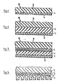
- composite films consist of a carrier layer, preferably a polyester film, such as Polyethylene terephthalate, which is crosslinked on one or both sides using known adhesion promoters, at least with a layer of NBR or other elastomers.
- a carrier layer preferably a polyester film, such as Polyethylene terephthalate, which is crosslinked on one or both sides using known adhesion promoters, at least with a layer of NBR or other elastomers.
- FIGS. 1-4 show four embodiments of such composite films which can be used as flat structures in the printing unit cylinder claimed.
- (2) is the adhesive layer.
- the carrier layer (1) preferably polyethylene terephthalate
- the carrier layer (1) can be crosslinked on one side with an elastomer layer (3) (Fig. 1), on one or both sides with one or two elastomer layer (s) (3 + 4) of different Shore A hardness ( Fig.2).
- the fabric can also consist of a carrier Layer (1), two elastomer layers (3 + 4) and an interposed driven layer (5) exist (Fig. 3), or also have an elastomer layer (4) with incorporated raster (Fig. 4).
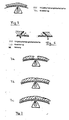
- a rubber covering according to FIG. 1 is selected as a flat structure for the construction of the printing unit cylinder claimed.
- the arrangement shown in FIG. 5 results between the roller body and the flat structure.
- the upper layer in the example the elastomer layer (3)
- the elastomer layer (3) is now at the clamping edges of the rubber covering, e.g. by planing, milling or grinding to such an extent that the part still occupied corresponds exactly to the circumference of the cylinder and the planed, milled or ground ends are of equal length.
- the elastomer layer (3) is shortened again on one or both sides to the extent that the stretching under the tensioning force.
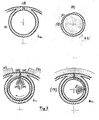
- the situation shown in FIG. 6 results for the flat structure.
- the elastomer mass (3) located above the base point B determines the extent of the increase in the total radius, i.e. the elevation depends on the angle ⁇ . If the angle ⁇ is 90 ° or more, there is no exaggeration, the purpose according to the invention is not achieved in the latter case.
- the rubber covering is tensioned, its curved surface above the clamping channel is increased to the total radius by means of a radial planer, radial milling cutter, radial scraper or radial grinding device, adjusted to the same or below it, and, as far as necessary, the tangential run-out taken into account in the total radius. In this way, it is possible to prevent the interference shock or channel blow.
- the minimum channel width required to clamp the ends of the rubber covering remaining after abrasion of the layer (3) depends on the total thickness of the covering.
- the minimum channel width is calculated as follows: generally 2 x base layer thickness 2 x 250 ⁇ m 500 ⁇ m minimum channel width.
- the minimum channel width is calculated generally 2 x covering thickness minus 2x abrasion thickness 2x1.95 mm - 2x0.85 mm 2.2 mm minimum channel width
- Printing unit cylinders for web offset printing (blanket cylinders), for high and flexographic printing (printing form and impression cylinders) and also for indirect gravure printing (blanket cylinders) can be equipped with the rubber covering which has been corrected and subsequently fixed in accordance with the invention in the manner described.
- the printing unit cylinder according to the invention consisting of a roller, a tensioning element with a narrowed tensioning channel and a flat structure laid out in the manner described, is also suitable for functioning as a flexographic printing roller.
- the type of the new pressure element allows the elastomer covering to be replaced in the shortest possible time. It is even conceivable to do without changing the printing roller. This is possible if the subject is laser-engraved separately and the elastomer printing form component is placed and clamped on the printing roller or core installed in the machine. A prerequisite for such a mode of operation is the dimensional identity and the same mechanical behavior of the cylinder in the laser engraving unit and that in the printing press.
- the surface of the rubber covering can also be designed in a known manner in relief, as is done in so-called cliché machines by pressing and vulcanizing.
- the printing unit cylinder described is a printing form cylinder.
- the elastomer plate joint can be closed with adhesives or a suitable adhesive.
- the correction of the rubber covering ends according to the invention can be carried out in a simple manner (planing, milling, grinding) and in the laid-on state. Due to the narrowing of the clamping channel, torsion-free clamping elements can be used and thus mechanically stable printing unit cylinders are created.
- the printing unit cylinder can be used in web offset printing (blanket cylinder) in indirect gravure printing (rubber cylinder), in high and flexographic printing (impression cylinder) or also in flexographic printing (printing form cylinder, flexographic printing roller).
Landscapes
- Engineering & Computer Science (AREA)
- Mechanical Engineering (AREA)
- Printing Plates And Materials Therefor (AREA)
- Supply, Installation And Extraction Of Printed Sheets Or Plates (AREA)
Priority Applications (4)
| Application Number | Priority Date | Filing Date | Title |
|---|---|---|---|
| EP87117263A EP0317656B1 (fr) | 1987-11-24 | 1987-11-24 | Cylindre d'unité d'impression comportant une couche de caoutchouc pour l'impression offset, flexographique, en creux, typographique |
| DE8787117263T DE3780313D1 (de) | 1987-11-24 | 1987-11-24 | Druckwerkszylinder mit gummibelag fuer hoch-. flexo-, tief- und rollenoffset-druck. |
| US07/273,383 US4907508A (en) | 1987-11-24 | 1988-11-17 | Printing cylinder with rubber coating for letterpress, flexography, rotogravure and rotary offset |
| JP63294815A JPH01165491A (ja) | 1987-11-24 | 1988-11-24 | 凸版、フレキソ、凹版及びロール・オフセット印刷用のゴム上張を有する印刷シリンダ |
Applications Claiming Priority (1)
| Application Number | Priority Date | Filing Date | Title |
|---|---|---|---|
| EP87117263A EP0317656B1 (fr) | 1987-11-24 | 1987-11-24 | Cylindre d'unité d'impression comportant une couche de caoutchouc pour l'impression offset, flexographique, en creux, typographique |
Publications (2)
| Publication Number | Publication Date |
|---|---|
| EP0317656A1 true EP0317656A1 (fr) | 1989-05-31 |
| EP0317656B1 EP0317656B1 (fr) | 1992-07-08 |
Family
ID=8197470
Family Applications (1)
| Application Number | Title | Priority Date | Filing Date |
|---|---|---|---|
| EP87117263A Expired - Lifetime EP0317656B1 (fr) | 1987-11-24 | 1987-11-24 | Cylindre d'unité d'impression comportant une couche de caoutchouc pour l'impression offset, flexographique, en creux, typographique |
Country Status (4)
| Country | Link |
|---|---|
| US (1) | US4907508A (fr) |
| EP (1) | EP0317656B1 (fr) |
| JP (1) | JPH01165491A (fr) |
| DE (1) | DE3780313D1 (fr) |
Cited By (5)
| Publication number | Priority date | Publication date | Assignee | Title |
|---|---|---|---|---|
| EP0614772A1 (fr) * | 1993-03-09 | 1994-09-14 | M.A.N.-ROLAND Druckmaschinen Aktiengesellschaft | Machine à imprimer pour procédé d'impression indirecte |
| FR2707555A1 (fr) * | 1993-07-17 | 1995-01-20 | Roland Man Druckmasch | Rouleau encreur à revêtement élastique tendu sur un noyau. |
| WO2001039977A1 (fr) * | 1999-12-02 | 2001-06-07 | Koenig & Bauer Aktiengesellschaft | Element d'impression d'une presse rotative |
| WO2001070512A1 (fr) * | 2000-03-21 | 2001-09-27 | Day International, Inc. | Blanchet souple de transfert d'image possedant un renforcement non extensible |
| EP1832419A3 (fr) * | 2006-03-07 | 2009-12-23 | WIFAG Maschinenfabrik AG | Elément d'atténuation de contraintes |
Families Citing this family (11)
| Publication number | Priority date | Publication date | Assignee | Title |
|---|---|---|---|---|
| US5798202A (en) * | 1992-05-11 | 1998-08-25 | E. I. Dupont De Nemours And Company | Laser engravable single-layer flexographic printing element |
| US5804353A (en) * | 1992-05-11 | 1998-09-08 | E. I. Dupont De Nemours And Company | Lasers engravable multilayer flexographic printing element |
| JP4309395B2 (ja) * | 2002-12-16 | 2009-08-05 | ケーニッヒ ウント バウエル アクチエンゲゼルシャフト | 印刷ブランケットシリンダのための印刷ブランケット装置および印刷ブランケット装置の製造方法 |
| JP4298702B2 (ja) * | 2002-12-16 | 2009-07-22 | ケーニッヒ ウント バウエル アクチエンゲゼルシャフト | 印刷機における印刷ブランケットシリンダのための印刷ブランケット装置および印刷ブランケット装置の製造方法 |
| US8904931B2 (en) * | 2003-11-10 | 2014-12-09 | Day International, Inc. | Printing blanket construction and method of making |
| DE102005013424A1 (de) * | 2005-03-21 | 2006-09-28 | Man Roland Druckmaschinen Ag | Gummisleeve |
| JP2008132721A (ja) * | 2006-11-29 | 2008-06-12 | Nitto Denko Corp | 印刷機用のクッションシート、印刷機、及び印刷方法 |
| KR101308447B1 (ko) * | 2006-12-20 | 2013-09-16 | 엘지디스플레이 주식회사 | 인쇄 장치 및 그를 이용한 박막 패터닝 방법 |
| US20100151170A1 (en) * | 2008-12-15 | 2010-06-17 | Tredegar Film Products Corporation | Forming screens |
| DE102010064414A1 (de) * | 2010-12-10 | 2012-09-27 | Manroland Web Systems Gmbh | Drucktuch,Verfahren zum Herstellen desselben und Spanneinrichtung eines Übertragungszylinders für ein Drucktuch |
| BR102013024227A2 (pt) * | 2013-09-20 | 2015-08-18 | Embalagens Flexíveis Diadema S A | Método de produção de uma estrutura laminada flexível, estrutura laminada flexível assim obtida, filme de polietieno mono estirado e embalagem formada pela estrutura laminada flexível |
Citations (6)
| Publication number | Priority date | Publication date | Assignee | Title |
|---|---|---|---|---|
| US2629324A (en) * | 1947-11-17 | 1953-02-24 | Commercial Lithograph Company | Apparatus for making lithograph blankets |
| FR2055867A5 (fr) * | 1969-08-01 | 1971-05-14 | Polygraph Leipzig | |
| US3765329A (en) * | 1971-09-28 | 1973-10-16 | A Kirkpatrick | Cylinder cover fastening devices |
| US3802952A (en) * | 1969-07-18 | 1974-04-09 | E Gurin | Biaxally stress-oriented plastic sheet laminated with nbr adhesive to rubber-coated paper |
| GB2167011A (en) * | 1984-11-16 | 1986-05-21 | Wifag Maschf | Rubber blanket cylinder for a rotary printing press |
| US4635550A (en) * | 1985-03-11 | 1987-01-13 | American Roller Company | Gap filler blanket for printing cylinder |
Family Cites Families (11)
| Publication number | Priority date | Publication date | Assignee | Title |
|---|---|---|---|---|
| US3649439A (en) * | 1968-09-25 | 1972-03-14 | Grace W R & Co | Printing element |
| US3584580A (en) * | 1969-08-25 | 1971-06-15 | Leipzig Veb Druckmasch Werke | Rubber sheet tensioning device for offset printing machines |
| BE760067A (fr) * | 1969-12-09 | 1971-06-09 | Applied Display Services | Procede et appareil pour la fabrication de plaques en relief ainsi que plaques pour impression ainsi obtenues |
| US3705072A (en) * | 1970-05-04 | 1972-12-05 | Minnesota Mining & Mfg | Underpacking for printing with dimensionally stable plastic core having elastomeric and pressure sensitive outer layers |
| US3730092A (en) * | 1971-03-05 | 1973-05-01 | Grace W R & Co | Magnetic sheet for impression cylinder |
| DE2225016C3 (de) * | 1972-05-23 | 1976-01-29 | Koenig & Bauer Ag | Vorrichtung zum aufspannen von biegsamen druckplatten auf formzylinder von rotationsdruckmaschinen |
| US3818651A (en) * | 1972-11-22 | 1974-06-25 | P Eells | Abrading and polishing wheels |
| US4537129A (en) * | 1980-07-25 | 1985-08-27 | W. R. Grace & Co. | Offset printing blanket |
| DE3338450C1 (de) * | 1983-10-22 | 1985-06-05 | M.A.N.- Roland Druckmaschinen AG, 6050 Offenbach | Einrichtung zum Einfuehren der Endabschnitte eines flexiblen Aufzuges in eine Grube eines Zylinders einer Druckmaschine |
| DE3540581A1 (de) * | 1985-11-15 | 1987-05-21 | Roland Man Druckmasch | Druckwerkzylinder mit einem in dessen zylindergrube angeordneten fuellstueck |
| GB8616952D0 (en) * | 1986-07-11 | 1986-08-20 | Hercules Inc | Printing plate |
-
1987
- 1987-11-24 EP EP87117263A patent/EP0317656B1/fr not_active Expired - Lifetime
- 1987-11-24 DE DE8787117263T patent/DE3780313D1/de not_active Expired - Fee Related
-
1988
- 1988-11-17 US US07/273,383 patent/US4907508A/en not_active Expired - Fee Related
- 1988-11-24 JP JP63294815A patent/JPH01165491A/ja active Pending
Patent Citations (6)
| Publication number | Priority date | Publication date | Assignee | Title |
|---|---|---|---|---|
| US2629324A (en) * | 1947-11-17 | 1953-02-24 | Commercial Lithograph Company | Apparatus for making lithograph blankets |
| US3802952A (en) * | 1969-07-18 | 1974-04-09 | E Gurin | Biaxally stress-oriented plastic sheet laminated with nbr adhesive to rubber-coated paper |
| FR2055867A5 (fr) * | 1969-08-01 | 1971-05-14 | Polygraph Leipzig | |
| US3765329A (en) * | 1971-09-28 | 1973-10-16 | A Kirkpatrick | Cylinder cover fastening devices |
| GB2167011A (en) * | 1984-11-16 | 1986-05-21 | Wifag Maschf | Rubber blanket cylinder for a rotary printing press |
| US4635550A (en) * | 1985-03-11 | 1987-01-13 | American Roller Company | Gap filler blanket for printing cylinder |
Non-Patent Citations (1)
| Title |
|---|
| PATENT ABSTRACTS OF JAPAN, vol. 8, no. 9 (M-268)[1446], 14. Januar 1984; & JP-A-58 171 958 (SUMITOMO JUKIKAI KOGYO K.K.) 08-10-1983 * |
Cited By (12)
| Publication number | Priority date | Publication date | Assignee | Title |
|---|---|---|---|---|
| EP0614772A1 (fr) * | 1993-03-09 | 1994-09-14 | M.A.N.-ROLAND Druckmaschinen Aktiengesellschaft | Machine à imprimer pour procédé d'impression indirecte |
| FR2707555A1 (fr) * | 1993-07-17 | 1995-01-20 | Roland Man Druckmasch | Rouleau encreur à revêtement élastique tendu sur un noyau. |
| WO2001039977A1 (fr) * | 1999-12-02 | 2001-06-07 | Koenig & Bauer Aktiengesellschaft | Element d'impression d'une presse rotative |
| WO2001039974A3 (fr) * | 1999-12-02 | 2001-11-15 | Koenig & Bauer Ag | Cylindre de transfert d'une rotative |
| EP1361053A3 (fr) * | 1999-12-02 | 2004-01-28 | Koenig & Bauer Aktiengesellschaft | Cylindre de blanchet d'une presse à imprimer |
| US6920824B2 (en) | 1999-12-02 | 2005-07-26 | Koenig & Bauer Aktiengesellschaft | Printing group of a rotary printing press |
| US7066090B2 (en) | 1999-12-02 | 2006-06-27 | Koenig & Bauer Aktiengesellschaft | Printing group of a rotary printing press |
| US7246557B2 (en) | 1999-12-02 | 2007-07-24 | Koenig & Bauer Aktiengesellschaft | Printing group of a rotary printing press |
| US7523703B2 (en) | 1999-12-02 | 2009-04-28 | Koenig & Bauer Aktiengesellschaft | Printing group of a rotary printing press |
| WO2001070512A1 (fr) * | 2000-03-21 | 2001-09-27 | Day International, Inc. | Blanchet souple de transfert d'image possedant un renforcement non extensible |
| US6530321B2 (en) | 2000-03-21 | 2003-03-11 | Day International, Inc. | Flexible image transfer blanket having non-extensible backing |
| EP1832419A3 (fr) * | 2006-03-07 | 2009-12-23 | WIFAG Maschinenfabrik AG | Elément d'atténuation de contraintes |
Also Published As
| Publication number | Publication date |
|---|---|
| DE3780313D1 (de) | 1992-08-13 |
| JPH01165491A (ja) | 1989-06-29 |
| EP0317656B1 (fr) | 1992-07-08 |
| US4907508A (en) | 1990-03-13 |
Similar Documents
| Publication | Publication Date | Title |
|---|---|---|
| EP0317656B1 (fr) | Cylindre d'unité d'impression comportant une couche de caoutchouc pour l'impression offset, flexographique, en creux, typographique | |
| DE69504889T2 (de) | Zylinder mit Drucktuch | |
| DE68917873T2 (de) | Drucktuch mit nichttexturierter Oberfläche. | |
| DE2446188B2 (de) | Bogenfuehrende mantelflaeche von gegendruckzylindern oder bogenueberfuehrungszylindern in rotationsoffsetdruckmaschinen | |
| DE19648494C2 (de) | Drucktuch für Offsetdruck | |
| EP0659585B1 (fr) | Blanchet d'impression à profil non-uniforme | |
| DE3539586A1 (de) | Verfahren zum aufbringen eines schutzbelages auf einen druckwerkzylinder mit vorrichtungen zur durchfuehrung des verfahrens | |
| EP0279295B1 (fr) | Unité d'encrage | |
| DE2932887C2 (de) | Rotationsdruckmaschine mit einer Einrichtung zur Verhinderung von Zylinderbewegungen | |
| DE10237205B4 (de) | Aufzug auf einer Walze, Anordnungen der Walze zu einer zweiten Walze sowie Druckwerke einer Druckmaschine mit der Walze | |
| DE2613688C2 (de) | Gummituchzylinder für eine Bogen-Rotationsoffsetdruckmaschine | |
| DE10060753A1 (de) | Verfahren zur fortlaufenden Herstellung von kanallosen, hülsenförmigen Gummitüchern für Offset-Druckmaschinen | |
| DE19926410A1 (de) | Gummituchzylinder in einer Rotationsdruckmaschine | |
| DE19515459C2 (de) | Gummituchzylinder | |
| DE60100546T2 (de) | Universelle Unterlage für ein gummibeschichtetes Gewebe auf Zylinder von Offsetdruckmaschinen | |
| DE68906168T2 (de) | Verfahren zum Befestigen und Positionieren von Offsetdruckplatten mit magnetischer Unterstützung und Druckplatte und Offsetdruckmaschine zur Durchführung des Verfahrens. | |
| EP1688251B1 (fr) | Unité d'impression d'une machine à imprimer | |
| EP1566269A1 (fr) | Cylindre pour l'impression avec un vide pour tendre | |
| DE9310713U1 (de) | Farbauftragwalze | |
| EP0984860A1 (fr) | Rouleau a garniture en caoutchouc et dispositif pour appliquer une garniture en caoutchouc | |
| EP1428660B1 (fr) | Cylindre porte-blanchet pour une machine d'impression offset | |
| DE2613687B2 (de) | Gununituchzylinder einer Rollen-Rotations-Offsetdruckmaschine mit einer Abflachung am Spannkanal | |
| EP1390202B1 (fr) | Procede de production d'une plaque d'impression pouvant etre directement gravee au laser, et plaque d'impression produite selon ledit procede | |
| EP1184172B1 (fr) | Cylindre porte-blanchet dans une machine offset rotative | |
| DE102015102906B4 (de) | Druckvorrichtung für Hochdruck und Tiefdruck |
Legal Events
| Date | Code | Title | Description |
|---|---|---|---|
| PUAI | Public reference made under article 153(3) epc to a published international application that has entered the european phase |
Free format text: ORIGINAL CODE: 0009012 |
|
| 17P | Request for examination filed |
Effective date: 19871211 |
|
| AK | Designated contracting states |
Kind code of ref document: A1 Designated state(s): CH DE ES FR GB IT LI SE |
|
| 17Q | First examination report despatched |
Effective date: 19901123 |
|
| GRAA | (expected) grant |
Free format text: ORIGINAL CODE: 0009210 |
|
| AK | Designated contracting states |
Kind code of ref document: B1 Designated state(s): CH DE ES FR GB IT LI SE |
|
| PG25 | Lapsed in a contracting state [announced via postgrant information from national office to epo] |
Ref country code: IT Free format text: LAPSE BECAUSE OF FAILURE TO SUBMIT A TRANSLATION OF THE DESCRIPTION OR TO PAY THE FEE WITHIN THE PRE;WARNING: LAPSES OF ITALIAN PATENTS WITH EFFECTIVE DATE BEFORE 2007 MAY HAVE OCCURRED AT ANY TIME BEFORE 2007. THE CORRECT EFFECTIVE DATE MAY BE DIFFERENT FROM THE ONE RECORDED.SCRIBED TIME-LIMIT Effective date: 19920708 Ref country code: FR Effective date: 19920708 Ref country code: SE Effective date: 19920708 Ref country code: GB Effective date: 19920708 |
|
| REF | Corresponds to: |
Ref document number: 3780313 Country of ref document: DE Date of ref document: 19920813 |
|
| PG25 | Lapsed in a contracting state [announced via postgrant information from national office to epo] |
Ref country code: ES Free format text: LAPSE BECAUSE OF FAILURE TO SUBMIT A TRANSLATION OF THE DESCRIPTION OR TO PAY THE FEE WITHIN THE PRESCRIBED TIME-LIMIT Effective date: 19921019 |
|
| EN | Fr: translation not filed | ||
| GBV | Gb: ep patent (uk) treated as always having been void in accordance with gb section 77(7)/1977 [no translation filed] |
Effective date: 19920708 |
|
| PLBE | No opposition filed within time limit |
Free format text: ORIGINAL CODE: 0009261 |
|
| STAA | Information on the status of an ep patent application or granted ep patent |
Free format text: STATUS: NO OPPOSITION FILED WITHIN TIME LIMIT |
|
| 26N | No opposition filed | ||
| PGFP | Annual fee paid to national office [announced via postgrant information from national office to epo] |
Ref country code: CH Payment date: 19940531 Year of fee payment: 7 |
|
| PGFP | Annual fee paid to national office [announced via postgrant information from national office to epo] |
Ref country code: DE Payment date: 19940916 Year of fee payment: 8 |
|
| PG25 | Lapsed in a contracting state [announced via postgrant information from national office to epo] |
Ref country code: LI Effective date: 19941130 Ref country code: CH Effective date: 19941130 |
|
| REG | Reference to a national code |
Ref country code: CH Ref legal event code: PL |
|
| PG25 | Lapsed in a contracting state [announced via postgrant information from national office to epo] |
Ref country code: DE Effective date: 19960801 |