EP0318982A2 - Trägerschicht für Flüssigkeitsstrahlkopf und Flüssigkeitsstrahlvorrichtung, versehen mit solch einem Kopf - Google Patents
Trägerschicht für Flüssigkeitsstrahlkopf und Flüssigkeitsstrahlvorrichtung, versehen mit solch einem Kopf Download PDFInfo
- Publication number
- EP0318982A2 EP0318982A2 EP88120024A EP88120024A EP0318982A2 EP 0318982 A2 EP0318982 A2 EP 0318982A2 EP 88120024 A EP88120024 A EP 88120024A EP 88120024 A EP88120024 A EP 88120024A EP 0318982 A2 EP0318982 A2 EP 0318982A2
- Authority
- EP
- European Patent Office
- Prior art keywords
- liquid jet
- jet head
- head according
- amorphous alloy
- substrate
- Prior art date
- Legal status (The legal status is an assumption and is not a legal conclusion. Google has not performed a legal analysis and makes no representation as to the accuracy of the status listed.)
- Granted
Links
Images
Classifications
-
- B—PERFORMING OPERATIONS; TRANSPORTING
- B41—PRINTING; LINING MACHINES; TYPEWRITERS; STAMPS
- B41J—TYPEWRITERS; SELECTIVE PRINTING MECHANISMS, i.e. MECHANISMS PRINTING OTHERWISE THAN FROM A FORME; CORRECTION OF TYPOGRAPHICAL ERRORS
- B41J2/00—Typewriters or selective printing mechanisms characterised by the printing or marking process for which they are designed
- B41J2/005—Typewriters or selective printing mechanisms characterised by the printing or marking process for which they are designed characterised by bringing liquid or particles selectively into contact with a printing material
- B41J2/01—Ink jet
- B41J2/135—Nozzles
- B41J2/14—Structure thereof only for on-demand ink jet heads
- B41J2/14016—Structure of bubble jet print heads
- B41J2/14088—Structure of heating means
- B41J2/14112—Resistive element
- B41J2/14129—Layer structure
-
- B—PERFORMING OPERATIONS; TRANSPORTING
- B41—PRINTING; LINING MACHINES; TYPEWRITERS; STAMPS
- B41J—TYPEWRITERS; SELECTIVE PRINTING MECHANISMS, i.e. MECHANISMS PRINTING OTHERWISE THAN FROM A FORME; CORRECTION OF TYPOGRAPHICAL ERRORS
- B41J2/00—Typewriters or selective printing mechanisms characterised by the printing or marking process for which they are designed
- B41J2/005—Typewriters or selective printing mechanisms characterised by the printing or marking process for which they are designed characterised by bringing liquid or particles selectively into contact with a printing material
- B41J2/01—Ink jet
- B41J2/135—Nozzles
- B41J2/14—Structure thereof only for on-demand ink jet heads
- B41J2002/14379—Edge shooter
-
- B—PERFORMING OPERATIONS; TRANSPORTING
- B41—PRINTING; LINING MACHINES; TYPEWRITERS; STAMPS
- B41J—TYPEWRITERS; SELECTIVE PRINTING MECHANISMS, i.e. MECHANISMS PRINTING OTHERWISE THAN FROM A FORME; CORRECTION OF TYPOGRAPHICAL ERRORS
- B41J2202/00—Embodiments of or processes related to ink-jet or thermal heads
- B41J2202/01—Embodiments of or processes related to ink-jet heads
- B41J2202/03—Specific materials used
Definitions
- This invention relates to a liquid jet recording head which performs recording by discharging liquid for recording such as ink, etc. by utilizing heat energy to form its droplets and attaching the droplets onto a recording medium such as a paper, to a substrate for the head and to a liquid jet apparatus having the head.
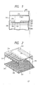
- Recording head to be used for the liquid jet recording method which utilizes heat energy for formation of droplets to be discharged generally comprises a discharge opening for discharging liquid for recording such as ink, etc.; a liquid path communicated to the discharge opening having a portion at which heat energy to be utilized for discharging liquid acts on liquid and an electrothermal transducer which is a heat energy generating means for generating the heat energy having a heat-generating resistor and a pair of electrodes connected to the heat-generating resistor, and has, for example, a structure shown in a separated state in the schematic perspective views of Fig. 2.
- the recording head disclosed in Japanese Laid-open Patent Application No. 55-126462 as shown in Fig. 1, consisted of a heat-generating resistor 208 for generating heat energy on a surface of support, electrodes 209, 210 for supplying electrical signals thereto formed by lamination according to thin film forming technique, etc. to form a substrate 202 for recording head, and further a liquid path 204 in contact with the heat-generating portion 201 of the heat generating resistor 208 and a discharge opening 217 formed on the substrate.
- One of the specific feature of the recording head resided in that no protective layer as seen in the prior art was laminated on at least the upper part of the heat-generating portion 201 of the heat-generating resistor 208, thus having a structure in which the heat energy generated by the heat-generating portion 201 of the heat-generating resistor 208 can be readily transmitted directly to the liquid in the liquid path 204.
- electrodes 209, 210 are made of a corrosion resistant material such as gold, it is not required to provide protective layer 213, 214 thereon, but when they are formed of a readily corrosive material such as Al, it is preferable that protective layers 213, 214 comprising an inorganic insulating material such as SiO2, SiN, etc. or a heat-resistant organic polymer such as polyimide, etc. as shown in the Figure at the portions other than the heat-generating portion 201 of the heat-generating resistor 208.
- the material for forming the heat-generating resistor 208 of the recording head of such constitution there have been used in the art materials exhibiting appropriate resistance values, specifically, noble metals (elements of the group VIII, etc.), high melting transition elements (elements of the groups III, IV, V, VI, etc.), alloys of these, or nitrides, borides, silicides, carbides of oxides of these metals, and further silicon-diffused resistors, or amorphous films composed mainly of carbon, etc.
- the heat-generating resistor layer is subject to heat for gasification of liquid, and cavitation shock created during droplet dischargigng and chemical action of liquid, it must be excellent in heat resistance, breaking resistance, liquid resistance, oxidation resistance, etc.
- single substance metals of noble metals, high melting transition metals, etc. have generally low specific resistance to pose a problem in the point of heat-generating efficiency, while in nitrides, borides, silicides, carbides, oxides of the above metals, or silicon-diffused resistors, or amorphous films composed mainly of carbon etc., there is sometimes the drawback of weak resistance to mechanical shock by cavitation shock, which may be estimated to be due to the fact that the atomic bonds of such compounds are covalent bonding in nature.
- the present inventors in order to solve the above problems, have made various investigations about the material for formation of heat-generating resistor satisfying the requirements as described above and consequently found a material which can satisfy all of the above requirements to accomplish the present invention.
- An object of the present invention is to provide a liquid jet recording head having a heat-generating resistor excellent in impact resistance, heat resistance, breaking resistance, liquid resistance, oxidation resistance, etc., a substrate for the head and a liquid jet recording apparatus having the head.
- Another object of the present invention is to provide a liquid jet head comprising: an electrothermal transducer having a heat-generating resistor formed using an amorphous alloy containing at least one selected from the group consisting of Ti, Zn, Hf, Nb, Ta and W as well as Fe, Ni and Cr, and a pair of electrodes connected electrically to said heat-generating resistor; a support for supporting said electrothermal transducer; and a liquid path formed on said support corresponding to the heat generating portion of said electrothermal transducer formed between said pair of electrodes and communicated to a discharge opening for discharging ink.
- Still another object of the present invention is to provide a substrate for liquid jet head comprising: an electrothermal transducer having a heat-generating resistor formed using an amorphous alloy containing at least one selected from the group consisting of Ti, Zn, Hf, Nb, Ta and W as well as Fe, Ni and Cr, and a pair of electrodes connected electrically to said heat-generating resistor; and a support for supporting said electrothermal transducer.
- Still another object of the present invention is to provide a liquid jet apparatus having the aforesaid liquid jet head.
- composition of the amorphous alloy to be used to form the heat-generating resistor of the present invention is represented by: M x (Fe 100-y-z Ni y Cr z ) 100-x wherein x is selected such that the alloy may be amorphous, at the value x, for example, in the range of 10 to 70 atomic%, preferably 20 to 70 atomic%.
- y should be desirably made 5 to 30 atomic% and z 10 to 30 atomic%.
- M represents at least one selected from the group consisting of Ti, Zr, Hf, Nb, Ta and W. That is, these elements may be used either singly or in a plural number thereof, as desired.
- the amorphous alloy film represented by the above compositional formula has high specific resistance, 150 - 300 ⁇ ohm ⁇ cm, and excellent properties as the constituent material of the heat-generating resistor directly in contact with liquid such as heat resistance, corrosion resistance, mechanical strength, etc.
- the layer of the heat-generating resistor (one shown by 208 in Fig. 1) by use of the amorphous alloy film
- conventional thin film deposition techniques, etc. may be applicable, but the sputtering method is suitable from the standpoint of obtaining readily a highly dense and strong amorphous alloy film.
- the constitutions of the liquid jet recording head of the present invention are not limited to the constitution as shown in Fig. 1 and Fig. 2, but they may have any desired constitutions.
- various protective layers as described above may be also used as provided on the heat-generating portion.
- the direction of ink supply to the heat generating portion of the liquid path may be substantially same as or different from (e.g. forming substantially a right angle with) the direction of ink discharge.
- the layer of heat generating resistor and the layer of electrode may be provided in a reverse (upset) arrangement.
- liquid jet head may be of a so-called full line type which has discharge openings over the whole range of the recording width of receiving material.
- the Al layer and the heat-generating resistor layer were subjected to patterning according to the photolithographic steps to a desired shape as shown in Fig. 2 to form an electrothermal transducer having a heat-generating resistor 208 and a pair of electrodes 209, 210.
- the electro-thermal transducer were spin coated photosensitive polyimide (Photoniece, produced by Toray) as the protective layers 213, 214, which were then subjected to patterning to a predetermined shape.
- photosensitive polyimide Photoniece, produced by Toray
- a covering member of glass plate 203 having a groove to form the liquid path 204 was laminated through an epoxy type adhesive to obtain a liquid jet recording head having the constitution primarily as shown in Fig. 1 and Fig. 2.
- a recording head was prepared in the same manner as in Example 1 except for forming by sputtering Ti25(Fe73Ni10Cr17)75 with a thickness of 2300 ⁇ as the heat-generating resistor layer.
- a recording head was prepared in the same manner as in Example 1 except for forming by sputtering Zr28(Fe73Ni10Cr17)72 with a thickness of 2000 ⁇ as the heat-generating resistor layer.
- a recording head was prepared in the same manner as in Example 1 except for forming by sputtering Hf28(Fe73Ni10Cr17)72 with a thickness of 2100 ⁇ as the heat generating resistor layer.
- a recording head was prepared in the same manner as in Example 1 except for forming by sputtering Nb56(Fe68Ni11Cr21)44 with a thickness of 2400 ⁇ as the heat-generating resistor layer.
- a recording head was prepared in the same manner as in Example 1 except for forming by sputtering W31(Fe68Ni11Cr21)69 with a thickness of 2100 ⁇ as the heat-generating resistor layer.
- a recording head was prepared in the same manner as in Example 1 except for forming by sputtering Ta32Ti18(Fe73Ni10Cr17)50 with a thickness of 1900 ⁇ as the heat-generating resistor layer.
- a recording head was prepared in the same manner as in Example 1 except for forming by sputtering Nb28Zr20(Fe73Ni10Cr17)52 with a thickness of 2200 ⁇ as the heat-generating resistor layer.
- a recording head was prepared in the same manner as in Example 1 except for forming by sputtering Hf35W22(Fe73Ni10Cr17)43 with a thickness of 1800 ⁇ as the heat-generating resistor layer.
- a recording head was prepared in the same manner as in Example 1 except for forming by sputtering Ta40Ti13Nb11(Fe73Ni10Cr17)36 with a thickness of 2000 ⁇ as the heat-generating resistor layer.
- a substrate for a liquid jet head and a liquid jet head formed by use of the substrate of the present invention was prepared in the same manner as in Example 1 except for adding a step to form a protective layer of SiO2 on an electro-thermal transducer before providing the protective layers 213, 214.
- the substrate for the liquid jet head and the liquid jet head formed by use of the substrate having various excellent properties such as durability etc. could be prepared.
- a substrate for liquid jet head and a liquid jet head formed by use of the substrate of the present invention was prepared in the same manner as in Example 2 except for adding a step to form a protective layer of SiN on an electro-thermal transducer before providing the protective layer 213, 214.
- the substrate for the liquid jet head and the liquid jet head formed by use of the substrate having various excellent properties such as durability etc. could be prepared.
- a recording head was prepared in the same manner as in Example 1 except for forming by sputtering HfB2 with a thickness of 2500 ⁇ as the heat-generating resistor layer.
- a recording head was prepared in the same manner as in Example 1 except for forming by sputtering Ti9(Fe73Ni10Cr17)91 with a thickness of 2400 ⁇ as the heat-generating resistor layer.
- the film having this composition was analyzed by X-ray diffractometry to be a polycrystalline film.
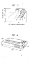
- Fig. 3 shows the Weibull plot of failure rate prepared from the results obtained. The time point when the resistance value of the heat-generating resistor exceeded 120% of the initial value was deemed as failure.
- the liquid path of the liquid jet head may be formed by forming first a wall forming member of the liquid path by use of, for example, a photosensitive resin and then bonding a top plate to the wall forming member.
- Fig. 4 is a schematic perspective view showing the appearance of a liquid jet apparatus equipped with the liquid jet head of the present invention.
- 1000 is the apparatus body, 1100 a power switch, 1200 an operation panel.
- the recording head formed by use of the substrate for liquid jet heads of the present invention by use of an amorphous alloy film having the specific composition as the heat-generating resistor as described above, has sufficient durability, even when it is made a constitution having no protective film on the heat-generating resistor.
- a recording head capable of effecting thermal conduction to liquid with good efficiency, which can be used with smaller power consumption and is excellent in durability can be provided by the present invention.
- a liquid jet head comprises, an electrothermal transducer having a heat-generating resistor formed using an amorphous alloy containing at least one selected from the group consisting of Ti, Zn, Hf, Nb, Ta and W as well as Fe, Ni and Cr, and a pair of electrodes connected electrically to said heat-generating resistor, a support for supporting said electrothermal transducer and a liquid path formed on said support corresponding to the heat generating portion of said electrothermal transducer formed between said pair of electrodes and communicated to a discharge opening for discharging ink.
Landscapes
- Particle Formation And Scattering Control In Inkjet Printers (AREA)
Applications Claiming Priority (2)
| Application Number | Priority Date | Filing Date | Title |
|---|---|---|---|
| JP62303712A JP2612580B2 (ja) | 1987-12-01 | 1987-12-01 | 液体噴射記録ヘッド及び該ヘッド用基板 |
| JP303712/87 | 1987-12-01 |
Publications (3)
| Publication Number | Publication Date |
|---|---|
| EP0318982A2 true EP0318982A2 (de) | 1989-06-07 |
| EP0318982A3 EP0318982A3 (en) | 1990-01-10 |
| EP0318982B1 EP0318982B1 (de) | 1993-10-27 |
Family
ID=17924342
Family Applications (1)
| Application Number | Title | Priority Date | Filing Date |
|---|---|---|---|
| EP88120024A Expired - Lifetime EP0318982B1 (de) | 1987-12-01 | 1988-11-30 | Trägerschicht für Flüssigkeitsstrahlkopf und Flüssigkeitsstrahlvorrichtung, versehen mit solch einem Kopf |
Country Status (4)
| Country | Link |
|---|---|
| US (1) | US5113203A (de) |
| EP (1) | EP0318982B1 (de) |
| JP (1) | JP2612580B2 (de) |
| DE (1) | DE3885241T2 (de) |
Cited By (6)
| Publication number | Priority date | Publication date | Assignee | Title |
|---|---|---|---|---|
| DE3941317A1 (de) * | 1989-03-22 | 1990-09-27 | Hewlett Packard Co | Thermischer tintenstrahldruckkopf |
| EP0473786A4 (en) * | 1990-02-26 | 1992-04-15 | Canon Kabushiki Kaisha | Substrate for ink-jet head |
| EP0750991A3 (de) * | 1995-06-30 | 1997-08-13 | Canon Kk | Tintenstrahlaufzeichnungskopf und Tintenstrahlaufzeichnungsapparat |
| EP1090763A3 (de) * | 1999-10-05 | 2001-08-29 | Canon Kabushiki Kaisha | Substrat für einen Tintenstrahlaufzeichnungskopf,Tintenstrahlaufzeichnungskopf, Tintenstrahlaufzeichnungseinheit und Tintenstrahlaufzeichnungsgerät |
| US7874646B2 (en) | 2005-04-04 | 2011-01-25 | Silverbrook Research Pty Ltd | MEMS bubble generator incorporating superalloy heater in direct contact with bubble formation liquid without intervening protective coating |
| US7901056B2 (en) | 2005-04-04 | 2011-03-08 | Silverbrook Research Pty Ltd | Printhead with increasing drive pulse to counter heater oxide growth |
Families Citing this family (9)
| Publication number | Priority date | Publication date | Assignee | Title |
|---|---|---|---|---|
| JP3320825B2 (ja) * | 1992-05-29 | 2002-09-03 | 富士写真フイルム株式会社 | 記録装置 |
| US5666140A (en) * | 1993-04-16 | 1997-09-09 | Hitachi Koki Co., Ltd. | Ink jet print head |
| US5641421A (en) * | 1994-08-18 | 1997-06-24 | Advanced Metal Tech Ltd | Amorphous metallic alloy electrical heater systems |
| US6022098A (en) * | 1995-08-10 | 2000-02-08 | Fuji Xerox Co., Ltd. | Ink-jet recorder |
| JP3194465B2 (ja) * | 1995-12-27 | 2001-07-30 | 富士写真フイルム株式会社 | インクジェット記録ヘッド |
| US5901425A (en) | 1996-08-27 | 1999-05-11 | Topaz Technologies Inc. | Inkjet print head apparatus |
| US6142612A (en) * | 1998-11-06 | 2000-11-07 | Lexmark International, Inc. | Controlled layer of tantalum for thermal ink jet printer |
| US20060221114A1 (en) | 2005-04-04 | 2006-10-05 | Silverbrook Research Pty Ltd | MEMS fluid sensor |
| EP2043864B1 (de) * | 2006-07-10 | 2013-09-25 | Zamtec Limited | Mems-blasenerzeuger |
Family Cites Families (19)
| Publication number | Priority date | Publication date | Assignee | Title |
|---|---|---|---|---|
| US4296421A (en) * | 1978-10-26 | 1981-10-20 | Canon Kabushiki Kaisha | Ink jet recording device using thermal propulsion and mechanical pressure changes |
| US4335389A (en) * | 1979-03-27 | 1982-06-15 | Canon Kabushiki Kaisha | Liquid droplet ejecting recording head |
| JPS5931942B2 (ja) * | 1979-03-27 | 1984-08-06 | キヤノン株式会社 | 液滴噴射記録装置 |
| DE3011919A1 (de) * | 1979-03-27 | 1980-10-09 | Canon Kk | Verfahren zur herstellung eines aufzeichnungskopfes |
| US4336548A (en) * | 1979-07-04 | 1982-06-22 | Canon Kabushiki Kaisha | Droplets forming device |
| JPS5833472A (ja) * | 1981-08-24 | 1983-02-26 | Canon Inc | 液体噴射記録ヘツド |
| JPS59106974A (ja) * | 1982-12-11 | 1984-06-20 | Canon Inc | 液体噴射記録ヘツド |
| JPH0624855B2 (ja) * | 1983-04-20 | 1994-04-06 | キヤノン株式会社 | 液体噴射記録ヘッド |
| JPH0613219B2 (ja) * | 1983-04-30 | 1994-02-23 | キヤノン株式会社 | インクジェットヘッド |
| JPS5913056A (ja) * | 1983-06-06 | 1984-01-23 | Res Inst Iron Steel Tohoku Univ | 高強度、耐疲労、耐全面腐食、耐孔食、耐隙間腐食、耐応力腐食割れ、耐水素脆性用アモルフアス鉄合金 |
| JPS60116451A (ja) * | 1983-11-30 | 1985-06-22 | Canon Inc | 液体噴射記録ヘツド |
| JPS60116452A (ja) * | 1983-11-30 | 1985-06-22 | Canon Inc | インクジェットヘッド |
| DE3446968A1 (de) * | 1983-12-26 | 1985-07-04 | Canon K.K., Tokio/Tokyo | Fluessigkeitsstrahlaufzeichnungskopf |
| JPS60159062A (ja) * | 1984-01-31 | 1985-08-20 | Canon Inc | 液体噴射記録ヘツド |
| DE3618533A1 (de) * | 1985-06-10 | 1986-12-11 | Canon K.K., Tokio/Tokyo | Fluessigkeitsstrahl-aufzeichnungskopf und diesen fluessigkeitsstrahl-aufzeichnungskopf enthaltendes aufzeichnungssystem |
| GB2176443B (en) * | 1985-06-10 | 1990-11-14 | Canon Kk | Liquid jet recording head and recording system incorporating the same |
| DE3618596A1 (de) * | 1985-06-11 | 1986-12-11 | Canon K.K., Tokio/Tokyo | Fluessigkeitsstrahl-aufzeichnungskopf und diesen fluessigkeitsstrahl-aufzeichnungskopf enthaltendes aufzeichnungssystem |
| JPH0729433B2 (ja) * | 1986-03-05 | 1995-04-05 | キヤノン株式会社 | 液体噴射記録ヘツドの作成方法 |
| US4737803A (en) * | 1986-07-09 | 1988-04-12 | Fuji Xerox Co., Ltd. | Thermal electrostatic ink-jet recording apparatus |
-
1987
- 1987-12-01 JP JP62303712A patent/JP2612580B2/ja not_active Expired - Fee Related
-
1988
- 1988-11-30 EP EP88120024A patent/EP0318982B1/de not_active Expired - Lifetime
- 1988-11-30 DE DE88120024T patent/DE3885241T2/de not_active Expired - Fee Related
-
1991
- 1991-08-06 US US07/742,728 patent/US5113203A/en not_active Expired - Fee Related
Cited By (9)
| Publication number | Priority date | Publication date | Assignee | Title |
|---|---|---|---|---|
| DE3941317A1 (de) * | 1989-03-22 | 1990-09-27 | Hewlett Packard Co | Thermischer tintenstrahldruckkopf |
| EP0473786A4 (en) * | 1990-02-26 | 1992-04-15 | Canon Kabushiki Kaisha | Substrate for ink-jet head |
| EP0750991A3 (de) * | 1995-06-30 | 1997-08-13 | Canon Kk | Tintenstrahlaufzeichnungskopf und Tintenstrahlaufzeichnungsapparat |
| US6042221A (en) * | 1995-06-30 | 2000-03-28 | Canon Kabushiki Kaisha | Ink-jet recording head and ink-jet recording apparatus |
| EP1090763A3 (de) * | 1999-10-05 | 2001-08-29 | Canon Kabushiki Kaisha | Substrat für einen Tintenstrahlaufzeichnungskopf,Tintenstrahlaufzeichnungskopf, Tintenstrahlaufzeichnungseinheit und Tintenstrahlaufzeichnungsgerät |
| US6435660B1 (en) | 1999-10-05 | 2002-08-20 | Canon Kabushiki Kaisha | Ink jet recording head substrate, ink jet recording head, ink jet recording unit, and ink jet recording apparatus |
| US7874646B2 (en) | 2005-04-04 | 2011-01-25 | Silverbrook Research Pty Ltd | MEMS bubble generator incorporating superalloy heater in direct contact with bubble formation liquid without intervening protective coating |
| US7901056B2 (en) | 2005-04-04 | 2011-03-08 | Silverbrook Research Pty Ltd | Printhead with increasing drive pulse to counter heater oxide growth |
| CN101489793B (zh) * | 2006-07-10 | 2012-06-13 | 西尔弗布鲁克研究有限公司 | Mems汽泡发生器 |
Also Published As
| Publication number | Publication date |
|---|---|
| JPH01145157A (ja) | 1989-06-07 |
| EP0318982B1 (de) | 1993-10-27 |
| DE3885241T2 (de) | 1994-03-03 |
| EP0318982A3 (en) | 1990-01-10 |
| JP2612580B2 (ja) | 1997-05-21 |
| DE3885241D1 (de) | 1993-12-02 |
| US5113203A (en) | 1992-05-12 |
Similar Documents
| Publication | Publication Date | Title |
|---|---|---|
| US4596994A (en) | Liquid jet recording head | |
| US5113203A (en) | Liquid jet head, substrate for said head and liquid jet apparatus having said head | |
| US4720716A (en) | Liquid jet recording head | |
| US4686544A (en) | Liquid jet recording head | |
| US4567493A (en) | Liquid jet recording head | |
| EP0493897B1 (de) | Thermischer Farbstrahldruckkopf mit Antriebschaltung und Verfahren zur Herstellung derselben | |
| US4694306A (en) | Liquid jet recording head with a protective layer formed by converting the surface of a transducer into an insulating material | |
| EP0286204A1 (de) | Grundplatte für Tintenstrahlaufzeichnungskopf | |
| US5660739A (en) | Method of producing substrate for ink jet recording head, ink jet recording head and ink jet recording apparatus | |
| EP0318981B1 (de) | Trägerschicht für Flüssigkeitsstrahlkopf und Flüssigkeitsstrahl vorrichtung, versehen mit solch einem Kopf | |
| JPS59106974A (ja) | 液体噴射記録ヘツド | |
| GB2188004A (en) | Liquid jet recording head | |
| EP1186411B1 (de) | Tintenstrahldruckkopfsubstrat, Tintenstrahldruckkopf und Tintenstrahlaufzeichnungsgerät | |
| EP0688672B1 (de) | Tintenstrahldruckkopf mit einer Kavitationssperrschicht von Palladium und einer Verbindungsschicht | |
| JPH0626887B2 (ja) | 液体噴射記録ヘツド | |
| JPS6131263A (ja) | 液体噴射記録ヘツド | |
| JP2656648B2 (ja) | インクジェットヘッド用基体、及び該基体を用いて形成されたインクジェットヘッド、並びに該ヘッドを具備するインクジェット装置 | |
| JPS60159060A (ja) | 液体噴射記録ヘツド | |
| JPS60116454A (ja) | 液体噴射記録ヘツド | |
| JPS60116453A (ja) | 液体噴射記録ヘツド | |
| JPH0470148B2 (de) | ||
| JPS60157869A (ja) | 液体噴射記録ヘツド | |
| JPH09277533A (ja) | インクジェットヘッド及びその製造方法 | |
| JPH02187354A (ja) | 液体噴射記録ヘッド用基体およびそれを用いた液体噴射記録ヘッド | |
| JPS59124871A (ja) | 液体噴射記録装置 |
Legal Events
| Date | Code | Title | Description |
|---|---|---|---|
| PUAI | Public reference made under article 153(3) epc to a published international application that has entered the european phase |
Free format text: ORIGINAL CODE: 0009012 |
|
| AK | Designated contracting states |
Kind code of ref document: A2 Designated state(s): DE FR GB IT |
|
| PUAL | Search report despatched |
Free format text: ORIGINAL CODE: 0009013 |
|
| AK | Designated contracting states |
Kind code of ref document: A3 Designated state(s): DE FR GB IT |
|
| 17P | Request for examination filed |
Effective date: 19900517 |
|
| 17Q | First examination report despatched |
Effective date: 19911106 |
|
| GRAA | (expected) grant |
Free format text: ORIGINAL CODE: 0009210 |
|
| AK | Designated contracting states |
Kind code of ref document: B1 Designated state(s): DE FR GB IT |
|
| REF | Corresponds to: |
Ref document number: 3885241 Country of ref document: DE Date of ref document: 19931202 |
|
| ET | Fr: translation filed | ||
| ITF | It: translation for a ep patent filed | ||
| PLBE | No opposition filed within time limit |
Free format text: ORIGINAL CODE: 0009261 |
|
| STAA | Information on the status of an ep patent application or granted ep patent |
Free format text: STATUS: NO OPPOSITION FILED WITHIN TIME LIMIT |
|
| 26N | No opposition filed | ||
| REG | Reference to a national code |
Ref country code: GB Ref legal event code: IF02 |
|
| PGFP | Annual fee paid to national office [announced via postgrant information from national office to epo] |
Ref country code: FR Payment date: 20021108 Year of fee payment: 15 |
|
| PGFP | Annual fee paid to national office [announced via postgrant information from national office to epo] |
Ref country code: GB Payment date: 20021127 Year of fee payment: 15 |
|
| PGFP | Annual fee paid to national office [announced via postgrant information from national office to epo] |
Ref country code: DE Payment date: 20021205 Year of fee payment: 15 |
|
| PG25 | Lapsed in a contracting state [announced via postgrant information from national office to epo] |
Ref country code: GB Free format text: LAPSE BECAUSE OF NON-PAYMENT OF DUE FEES Effective date: 20031130 |
|
| PG25 | Lapsed in a contracting state [announced via postgrant information from national office to epo] |
Ref country code: DE Free format text: LAPSE BECAUSE OF NON-PAYMENT OF DUE FEES Effective date: 20040602 |
|
| GBPC | Gb: european patent ceased through non-payment of renewal fee |
Effective date: 20031130 |
|
| PG25 | Lapsed in a contracting state [announced via postgrant information from national office to epo] |
Ref country code: FR Free format text: LAPSE BECAUSE OF NON-PAYMENT OF DUE FEES Effective date: 20040730 |
|
| REG | Reference to a national code |
Ref country code: FR Ref legal event code: ST |
|
| PG25 | Lapsed in a contracting state [announced via postgrant information from national office to epo] |
Ref country code: IT Free format text: LAPSE BECAUSE OF NON-PAYMENT OF DUE FEES;WARNING: LAPSES OF ITALIAN PATENTS WITH EFFECTIVE DATE BEFORE 2007 MAY HAVE OCCURRED AT ANY TIME BEFORE 2007. THE CORRECT EFFECTIVE DATE MAY BE DIFFERENT FROM THE ONE RECORDED. Effective date: 20051130 |