EP0319225A2 - Methode und Apparat für lineare kombinatorische Wägung - Google Patents
Methode und Apparat für lineare kombinatorische Wägung Download PDFInfo
- Publication number
- EP0319225A2 EP0319225A2 EP88311248A EP88311248A EP0319225A2 EP 0319225 A2 EP0319225 A2 EP 0319225A2 EP 88311248 A EP88311248 A EP 88311248A EP 88311248 A EP88311248 A EP 88311248A EP 0319225 A2 EP0319225 A2 EP 0319225A2
- Authority
- EP
- European Patent Office
- Prior art keywords
- product
- weight
- charges
- weighing
- cups
- Prior art date
- Legal status (The legal status is an assumption and is not a legal conclusion. Google has not performed a legal analysis and makes no representation as to the accuracy of the status listed.)
- Withdrawn
Links
Images


Classifications
-
- G—PHYSICS
- G01—MEASURING; TESTING
- G01G—WEIGHING
- G01G19/00—Weighing apparatus or methods adapted for special purposes not provided for in the preceding groups
- G01G19/387—Weighing apparatus or methods adapted for special purposes not provided for in the preceding groups for combinatorial weighing, i.e. selecting a combination of articles whose total weight or number is closest to a desired value
- G01G19/393—Weighing apparatus or methods adapted for special purposes not provided for in the preceding groups for combinatorial weighing, i.e. selecting a combination of articles whose total weight or number is closest to a desired value using two or more weighing units
Definitions
- the present invention relates generally to the field of computerized weighing systems and, more particularly to a method and apparatus for combination weighing utilizing in-line weighing hoppers that are charged by volumetric cups in a plurality of side-by-side feed lanes.
- quantities of product having a portion of the target weight are distributed to a plurality of scale-controlled hoppers arranged in a circle.
- the weighed product is fed from each of the hoppers to a plurality of storage cups associated with each of the hoppers.
- the product weight associated with each storage cup is registered. Specific combinations of storage cups are scanned to determine whether the combined product weights therein add to make the desired weight (within an acceptable limit above the target weight).
- the first combination found to make the target weight is used, and the appropriate storage cups are emptied to a container for receiving the product.
- the primary concerns in designing the combination weighing apparatus are to (1) provide relatively accurate portions of the sticky/irregular product to be weighed in the hoppers; (2) minimize the surface contact between the apparatus and the product during handling and (3) minimize the number of product transfers necessary to complete the weighing and delivering operation. These primary concerns must be addressed without adversely affecting the ability to provide product with the desired target weight during continuous machine operation over extended periods of time.
- a primary object of the present invention to provide an apparatus and method of combination weighing allowing high efficiency operation providing consistent and accurate delivery of a target weight of product under specialized product conditions and during extended, continuous machine operation.
- Another object of the present invention is to provide a method and apparatus for combination weighing specially adapted for use with product that is difficult to handle.
- Still another object of the present invention is to provide a method and apparatus for combination weighing that minimizes the surface contact between the apparatus and the product.
- a further object of the present invention is to provide a highly efficient and effective method and apparatus for combination weighing of irregular, sticky product that minimizes the number of product transfers.
- a further object of the present invention is to provide an arrangement that minimizes product build-up on the apparatus so as to maintain machine performance even over an extended period of continuous operation.
- an improved apparatus for combination weighing wherein a target weight of product is delivered to a receptacle or container, such as a plate, from a selection of product quantities or charges.
- the apparatus includes a plurality of transfer conveyors arranged side-by-side so as to form a series of product feed lanes.
- Each transfer conveyor includes a plurality of volumetric cups designed to receive and hold, for example, a quantity from 1/4 to 1/2 of the target weight of product to be delivered by the apparatus.
- Each transfer conveyor has associated therewith at its discharge end a weighing hopper.
- Each weighing hopper is designed to receive an individual product charge by free-fall discharge from one of the volumetric cups as the transfer conveyor is advanced in stepped fashion.
- the individual product charges that make the target weight are then dumped from selected weighing hoppers onto an underlying plate or container.
- These plates are supported on a conveyor running substantially perpendicular to the transfer conveyors and beneath each of the weighing hoppers.
- a control system is provided for operating the transfer and plate conveyors, as well as for selecting the combination of weighing hoppers having a total weight of product within an acceptable range above the target weight. More specifically, the control system includes various components that are provided for establishing acceptable product weight range limit to be achieved.
- the control system also allows for the registering of the weight of the individual product charges in each of the weighing hoppers.
- the control system circuitry scans combinations of weighing scales and calculates the total product weight of the combinations.
- the control system operates a product charge dumping mechanism on each of the selected weighing hoppers so that the desired weight of product is delivered to a particular plate or other receptacle as it advances on the underlying conveyor.
- the control system also actuates the product charge transfer conveyor associated with each weighing hopper being dumped so that the product charge from the next volumetric cup in that lane is delivered to the weighing hoppers.
- the volumetric cups and weighing hoppers may be coated with a non-stick material (such as available from Dupont de Nemours under the trademark Teflon) for easier product discharge.
- a non-stick material such as available from Dupont de Nemours under the trademark Teflon
- the cups may be heated by washing with warm water jets to provide efficient release for free-fall to the hopper. It has been discovered that this approach is also highly effective to reduce residual build-up that would otherwise adversely affect or degrade machine performance in delivering the desired product weight to, as well as from the hopper.
- a solvent other than water may be used.
- Alternative cleaning machanisms include high pressure warm air jets and/or a water or solvent bath, depending on the particular characteristics of the product being weighed for packaging.
- a guide collar may be provided to assure proper direction of the product being discharged from the volumetric cups into the weighing hoppers, and/or from the weighing hoppers to locate the product on the individual plates.
- the apparatus also includes a mechanism for indicating the weight trend of the manually loaded product charges being delivered to the weighing hoppers by the transfer conveyors in the individual feed lanes. More specifically, for any particular target weight, there is a desired weight range into which the individual product charges should fall. By indicating the weight trend, the apparatus of the present invention allows the operator to improve the quality of the product charges. Thus enhanced, the target weight may be made more efficiently and effectively with the least amount of product give-away.
- the indicating mechanism may include a high weight and low weight indicator that are actuated when the weight of the individual product charges falls outside of the desired range.
- a high weight and low weight indicator that are actuated when the weight of the individual product charges falls outside of the desired range. This is a particularly important feature when the weight of a particular volume of product may vary significantly from day to day as, for example, due to moisture content of the product and/or ambient temperature and humidity. The goal is, of course, to assure that the product charge weight remains uniform, and to do this the volume in the cups must be varied.
- such an indicator by sight and/or sound alerts the individual manually filling the volumetric cups, or may be used through circuitry to adjust the discharge of an automatic cup filling machine so that the individual product charges remain within acceptable limits for the most efficient and effective combination weighing.
- the in-line array of transfer conveyors are mounted on a first frame, and the corresponding weighing hoppers are supported on a second frame separate from the first frame.
- the first frame is formed as a cantilever so as to overlie the second frame and lock in position for proper operation. Once the operating shift is completed, however, the frames may be released and separated so as to allow the best possible access for cleaning sticky product build-up. Not only does the improved access reduce the necessary down time for system cleaning, but it ensures a more complete cleaning so that the machines return to operation at maximum efficiency.
- the dumping mechanism of the hopper of the present invention is also designed for maximum efficiency and speed of operation. More specifically, the dumping mechanism includes a double rotary door in the weighing hopper that provides a series of opposed radial support panels.
- a mechanism such as a ram actuator, is provided to actuate the door and dump the product charge from the first pair of support panels to a selected plate, while substantially simultaneously moving the second pair of support panels in position to receive the next product charge from the transfer conveyor.
- the rotary door includes a pair of meshing gears, each preferably supporting three radial panels.
- the ram actuator engages a pin on one of the gears in order to provide cooperating movement of rotary doors.
- the volumetric cups of the transfer conveyors are divided into two or more groups.
- the first group may be designed to receive and hold between 1/3 and 1/2 of the target weight of product while the second group may be designed to receive and hold between 1/4 and 1/3 of the target weight of product.
- the first group of volumetric cups are provided on the transfer conveyors to deliver the relatively heavy (1/3 to 1/2 weight) product charges to the weighing hoppers located along an upstream end of the plate conveyor. Consequently, the second group of volumetric cups are provided on the transfer conveyors for delivery of relatively light (1/4 to 1/3 weight) product charges to the weighing hoppers located along a downstream end of the plate conveyor.
- the ideal weight is 1/3 the total, which is within both ranges of target weights.
- a method of combination weighing includes the step of charging the volumetric cups either manually or automatically with product.
- the product is then delivered directly from the cups of the transfer conveyors into corresponding weighing hoppers where the charges are weighed, and upon command delivered directly to a plate or container for packaging.
- this method minimizes the surface contact between the product and the apparatus as well as the number of product transfers.
- this streamlined handling allows faster, more efficient operation and more accurate weighing, particulary when weighing and delivering a sticky product.
- the method may also include a step of selecting the first combination of weighing hoppers providing a total product weight within an acceptable range above the target weight.
- a step of selecting the first combination of weighing hoppers providing a total product weight within an acceptable range above the target weight.
- the method also includes a step of selecting a combination of two, three or more separate weighing hoppers to provide a total product weight within the acceptable range.
- a step of selecting a combination of two, three or more separate weighing hoppers to provide a total product weight within the acceptable range.
- the product charges are divided into two groups.
- the first group of charges each weigh between 1/3 and 1/2 of the target weight and the second group of charges each weigh between 1/4 and 1/3 of the target weight.
- the first or heavier group is provided on the transfer conveyors located along an upstream end of the plate conveyor while the second group is provided on the transfer conveyors located on a downstream end of the plate conveyor.
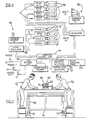
- FIG. 1 showing the combination weighing apparatus 10 of the present invention particularly adapted for use with difficult to handle product.
- the apparatus is specially designed to select from a number of product charges and provide a target weight of product into or onto a receptacle, such as a plate P.
- the apparatus may be used, for example, to make up a desired weight of any sticky or irregular product that exhibits inconsistent flow characteristics.
- An example of such a product is cooked beef tips ready for freezing on the plate P of a TV dinner.
- the apparatus 10 includes a plurality of product charge transfer conveyors 12.
- the transfer conveyors 12 are arranged side-by-side and mounted to a first frame 14 in parallel so as to provide a series of product feed lanes.
- Each transfer conveyor 12 includes a drive chain 16 extended over drive sprocket 18 and idler sprocket 20 (see Figure 3).
- a series of volumetric cups 22 are mounted at spaced intervals along the chain 16 by means of lugs 24 at the trailing end of the cups.
- each volumetric cup 22 includes an upper flange 26 that extends. fully around a product receiving basin 28. The flange 26 is designed so that when the cup 22 is positioned along the upper run of the transfer conveyor 12, the flange substantially abuts the flange of adjacent volumetric cups; not only in front and behind, but on the left and right sides as well.
- Each transfer conveyor 12 is advanced in stepped fashion, one volumetric cup 22 at a time, by means of a ram actuator 30.
- the ram actuator 30 is pivotally mounted to the frame 14 that supports the transfer conveyor 12.
- the distal end of the actuator rod 32 is mounted by means of a pin 34 to the chain drive sprocket 18 with a one way clutch.
- the actuator 30 pivots and the drive sprocket 18 oscillates to advance the transfer conveyor chain 16 and dump the product charge C contained in each volumetric cup 22.
- the product free falls through a guide collar 36 into an underlying weighing hopper 38 (see Figure 3 in particular).
- a cup washer unit 40 including a water jet 41 provides a heated water spray under pressure into the basin 28 of each cup, as well as across the flange 26, if desired.
- the tallow and product residue drains from the cup 22 with the wash water into an underlying pan 42 that directs the wash water flow to a drain (not shown).
- the weight of the product charge C is measured by the corresponding scales and readied for access by the computer control unit 44 (see Figure 9). Since a scale S/weighing hopper 38 is provided at the end of each transfer conveyor 12, a number of product charges of calculated weight equal to the number of transfer conveyors 12 or feed lanes are available for selection to make the desired target weight of product for delivery to each plate P (note also Figure 11).
- the control unit 44 in the form of a software controlled microprocessor, scans combinations of weighing hoppers 38, calculates the total product weight contained in those hoppers and compares that total weight to an acceptable range of product weight to be achieved above the desired target weight. For maximum speed of operation, the first combination of weighing hoppers 38 that contain a total product weight within the desired range are selected for delivery of product. The selected hoppers 38 then dump the product charges contained therein onto the plate P to make the desired weight as the plate P is advanced underneath the hoppers by the conveyor 46.
- each weighing hopper 38 includes a double rotary door generally designated by reference numeral 48.
- Each door includes cooperating first and second radial support panels 50. As shown in Figures 4A, 6A and 6B, when closed the opposed panels 50 receive and support the product charge C that is delivered from the volumetric cup 22 of the associated transfer conveyor 12.
- Actuation of the rotary door 48 is controlled by means of a ram actuator 52 that is pivotally connected to an actuating arm 54.
- Directional movement of the arm 54 is controlled by a guide plate 56 having a groove 58 receiving a guide pin 60 connected to the arm.
- the ram actuator 52 is retracted as shown by the action arrow A in Figures 6B - 6D, the distal end of the arm engages an actuator pin 62 on gear 64 of the rotary door 48.
- the gear 64 meshes with the gear 66 so that the cooperating panels 50 forming the double door 48 move in unison.
- the panels 50 open and the product charge C is dumped from the weighing hopper 38 onto the underlying plate P (see also Figures 3 and 4B).
- This substantially simultaneous operating of the panels 50, 50′ of the weighing hopper 38 serves to greatly increase the operating efficiency of the machine by allowing the immediate delivery of the next charge to the weighing hopper. Further, since the next charge can be delivered to the hopper sooner, there is more time between operating cycles for the charge to settle and a true weight for the new charge to be obtained. Thus, weighing errors are substantially eliminated and more efficient and effective overall machine operation is provided.
- the weighing hoppers 38 of the present invention are designed to be non-stick for easier and more complete discharge of the product. This, of course, can be achieved through a number of means including the provision of a Teflon surface to both the sides of the hopper and the operative side of the rotary door panels 50, 50′. Further each hopper 38, including the rotary door 48 may be heated in order to improve the flow characteristics of the product. In any event, the adverse effects of tallow and residue buildup on the integrity of the hopper operation is substantially avoided.
- a further concern that is addressed in an advantageous manner by the apparatus 10 relates to the total wash-down process at the end of each operating cycle. This is a particularly important concern with sticky products, such as beef tips, where tallow and other residue such as grease, could otherwise become caked on the equipment and actually spoil over time creating a totally unacceptable condition.
- the present invention is designed to allow the most effective and efficient access to all parts of the apparatus 10 so that maximum cleanliness may be easily assured.
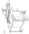
- the transfer conveyors 12 are all mounted on a single frame 14 (see Figure 7). As shown in Figures 5 and 8, the weighing hoppers 38 are all mounted on a second, separate frame 70.
- the transfer conveyor frame 14 is formed as a cantilever so as to readily overlie the weighing hopper frame 70.
- the weighing hopper frame 70 is also formed as a cantilever so as to overlie the plate conveyor 46.
- the frames When cleaning is completed, the frames may be easily aligned and retained in position to allow rapid restart of the apparatus 10. More specifically, the inner surfaces of the frame 14 interact with the outer surfaces of the frame 70 so as to direct and hold the two frames into proper alignment. For example, cam-shaped positioning blocks 73, 75 on the frames 14, allow the frames to be positioned and locked together in proper position. Of course, additional locking pins or the like (not shown) may be employed under certain operating conditions where firmer coupling together is desired.
- scales S each include an individual cantilever arm 74.
- the arm 74 is adapted to receive and support its respective weighing hopper 38 (see Figure 5). More specifically, each arm 74 includes upwardly and outwardly opening retainer slots 76, 78, respectively, that provide quick release of mounting rods 80, 82 of the weighing hopper 38.
- a hopper 38 simply drops down and swings into position (note action arrows) for operation.
- a hopper 38 may be simply and easily removed for cleaning or repair without disrupting operation of the remaining feed lanes.
- the present method of combination weighing to provide a target weight of product is particularly efficient. Initially, the volumetric cups 22 of the transfer conveyors 12 are each charged with product C. This may be accomplished manually by operators O A , O B as shown in Figure 2, where the product is sticky and not adapted for satisfactory machine feeding.
- each transfer conveyor 12 is operated in stepped fashion by an actuator 30 in response to the control unit 44 so as to cause the product charge from one volumetric cup 22 to be delivered to the corresponding weighing hopper 38.
- the control unit 44 Upon delivery of the product charge C to a weighing hopper 38, the control unit 44 actuates the cup washer unit 40 to clean the next cup and registers the weight of the charge delivered to the hopper.
- the control unit 44 scans various combinations of scales S with the weighing hoppers 38 and calculates the total weight of the product charges contained in those hoppers. The first combination that provides a total product weight within a previously established acceptable range at the target weight is then selected.
- the selected scale S/weighing hoppers 38 in a timed manner dump their individual product charges onto the plate P as it advances beneath the hoppers on the conveyor 46.
- both the actuators 52 that operate the double rotary doors 48 of the hoppers 38 and plate conveyor drive 46a operate in response to signals from the control unit 44 (see Figure 9).
- the weights of each product charge delivered to the volumetric cups 22 are simple fractions of the target weight. More specifically, combinations of simple fractions serve to reduce overweight (i.e. product give-away) while also reducing the percentage of missed weight discharges where no combination of individual product charges fall within the predetermined acceptable time window.
- control unit 44 is programmed to preferably select a combination of three separate weighing hoppers 38 to make the target weight. In this way, the product charges selected will average 1/3 the target weight.
- one group of volumetric cups 22 (group A) is designed to receive from 1/4 to 1/3 the target weight of product.
- Another group of volumetric cups 22 (group B) is designed to receive from 1/3 to 1/2 the target weight.
- the weight of product in each cup 22 corresponds to the desired value of 1/3 the target weight (note in Figure 10 the relatively small percentage of missed discharges obtained when weights are maintained as close as possible to 1/3 the target weight).
- a sufficient weight range is provided to allow compensation for loading errors caused by the problems discussed above. Thus, improved overall efficiency of operation is possible.
- one operator O A is assigned to charge all the cups 22 of one group and the other operator O B all the cups of the other group.
- group A receives from 1/4 to 1/3 the target weight of product (see Figure 9) while all of the volumetric cups of group B are charged with from 1/3 to 1/2 the target weight of product.
- the target weight is 85 grams
- operator O A charges the volumetric cups 22 with from 21.25 to 28.33 grams.
- operator O B charges the volumetric cups 22 with from 28.33 to 42.5 grams of product.
- Indicator monitors designated generally by reference numerals 86, 88 provide the respective operators O A , O B with feed back information regarding the weight trend of product charges that each is delivering to the volumetric cups 22.
- the monitors 86, 88 serve to assure that the appropriate desired charged weight is being delivered in all cases.
- the quality of charge weights from which the control unit 44 selects its combinations is improved. Consequently, overall machine performance and efficiency is enhanced.
- the indicator monitors 86, 88 may include any appropriate device providing a visual and/or audio signal.
- a dual light tower embodies the indicator monitors in drawing Figures 1 and 2.
- the first monitor 86 directs the operator O A charging the volumetric cups of group A while the other light tower directs the operator charging the volumetric cups of group B.
- the control unit 44 operates through the regulator 89 to actuate the upper light 90.
- the lower light is actuated.
- the middle light 94 is actuated thereby indicating that the operator O A is placing the desired weight of product in the volumetric cups 22.
- the operation is, of course, identical (but for different weight limits) for the monitor 88 which directs the operator O B filling the volumetric cups 22 of group B.
- the method includes the additional step of providing the volumetric cups 22 of group B (i.e. those containing 1/3 to 1/2 of the target weight) on the transfer conveyor feed lanes located upstream relative to the direction of the movement of the plate conveyor 46. Consequently, the volumetric cups of group A are located downstream.
- upstream weighing hoppers 38 when selecting a combination of weighing hoppers to provide a total product weight within the acceptable range, faster operating speeds may be obtained.
- the target weight for a plate P be made as shown in full line with three total charges, two of which are from weight group B (i.e. hoppers 1 and 4).
- the target weight may, however, be made when necessary with two of the three charges being provided from weight group A (i.e. hoppers 5 and 8) as shown in dashed line designated plate P1.
- the apparatus 10 provides highly efficient operation and is particularly adapted for weighing and delivering a target weight of product that is sticky, irregular or in some other way is difficult to handle.
- product charges directly from the volumetric cups 22 of the transfer conveyors 12 to weighing hoppers 38 and from there directly to a plate P, surface contact with the product is minimized.
- Product buildup and residue on the apparatus 10 are thereby maintained at an absolute minimum so as to maintain the most efficient, effective and accurate weighing possible, even over extended periods of continuous operation.
- the efficiency is further maximized by providing the highest possible quality of product charges from which to select combinations for making the target weight.
- trend indicator monitors 86, 88 are provided for indicating to the operator whether the product charges being delivered to the volumetric cups fall within the desired weight range that allow the apparatus 10 to operate at maximum speed with minimum product loss from overweight. Efficiency is also enhanced by programming which directs the apparatus 10 to select three hoppers to make the target weight. The apparatus 10 also prefers relatively heavy, upstream hoppers during selection.
Landscapes
- Physics & Mathematics (AREA)
- General Physics & Mathematics (AREA)
- Weight Measurement For Supplying Or Discharging Of Specified Amounts Of Material (AREA)
- Basic Packing Technique (AREA)
Applications Claiming Priority (2)
| Application Number | Priority Date | Filing Date | Title |
|---|---|---|---|
| US07/126,915 US4821820A (en) | 1987-11-30 | 1987-11-30 | Method and apparatus for linear combination weighing |
| US126915 | 1987-11-30 |
Publications (2)
| Publication Number | Publication Date |
|---|---|
| EP0319225A2 true EP0319225A2 (de) | 1989-06-07 |
| EP0319225A3 EP0319225A3 (de) | 1990-10-10 |
Family
ID=22427359
Family Applications (1)
| Application Number | Title | Priority Date | Filing Date |
|---|---|---|---|
| EP19880311248 Withdrawn EP0319225A3 (de) | 1987-11-30 | 1988-11-28 | Methode und Apparat für lineare kombinatorische Wägung |
Country Status (4)
| Country | Link |
|---|---|
| US (1) | US4821820A (de) |
| EP (1) | EP0319225A3 (de) |
| AU (1) | AU2518288A (de) |
| SE (1) | SE8804312L (de) |
Cited By (3)
| Publication number | Priority date | Publication date | Assignee | Title |
|---|---|---|---|---|
| EP0640814A1 (de) * | 1993-08-24 | 1995-03-01 | ISHIDA CO., Ltd. | Verfahren und Apparat zur kombinatorischen Wägung oder Zählung |
| EP0642003A1 (de) * | 1993-09-08 | 1995-03-08 | ISHIDA CO., Ltd. | Kombinatorische Wäge- oder Zählmethode und -apparat |
| EP0893674A1 (de) * | 1997-07-25 | 1999-01-27 | Ishida Co., Ltd. | Kombinatorischer Wägeapparat mit zuverlässiger kombinatorischen Berechnung |
Families Citing this family (37)
| Publication number | Priority date | Publication date | Assignee | Title |
|---|---|---|---|---|
| DE3826399C2 (de) * | 1988-08-03 | 2001-08-30 | Wilhelm Ludwig Kraemer | Reinigungsanlage für Waagen, insbesondere Kombinationswaagen |
| WO1992005410A1 (fr) * | 1990-09-17 | 1992-04-02 | Anritsu Corporation | Systeme de mesure servant a mesurer facilement avec un grande precision une large gamme de produits, y compris des substances visqueuses |
| AU647335B2 (en) * | 1990-09-17 | 1994-03-17 | Anritsu Corporation | Metering system capable of easily effecting high-accuracy metering for various works including sticky materials |
| DE69317852T2 (de) * | 1992-05-15 | 1998-08-20 | Ishida Scale Mfg Co Ltd | Teilmengenwaagen mit Taraberücksichtigungen einer verpackten Ware. |
| AU668577B2 (en) * | 1992-08-17 | 1996-05-09 | Precision Preweighs Pty. Ltd. | Method and apparatus for the provision of prepackaged components |
| DK80593D0 (da) * | 1993-07-06 | 1993-07-06 | Scanvaegt As | Fremgangsmaade og anlaeg til udvejning af genstandsportioner |
| WO1995022042A1 (en) * | 1994-02-15 | 1995-08-17 | Precision Preweighs Pty. Ltd | Method and apparatus for the provision of pre-packaged components |
| IS1758B2 (is) * | 1998-03-05 | 2002-09-20 | Pols Hf. | Aðferð til nákvæms og sjálfvirks þyngdarsamvals úr raðflæði stykkja |
| JP2001050803A (ja) * | 1999-08-06 | 2001-02-23 | Ishida Co Ltd | 組合せ計量装置 |
| JP4611568B2 (ja) * | 2000-07-24 | 2011-01-12 | 株式会社イシダ | 組合せ計量装置およびシステム |
| JP2002206964A (ja) * | 2001-01-09 | 2002-07-26 | Ishida Co Ltd | 組合せ計量装置 |
| JP2003214936A (ja) * | 2002-01-21 | 2003-07-30 | Ishida Co Ltd | 組合せ計量装置 |
| US20060162970A1 (en) * | 2003-07-17 | 2006-07-27 | Petur Gudjonsson | Method and a system for batching items into receptacles |
| US20050155978A1 (en) * | 2004-01-15 | 2005-07-21 | Gainco, Inc. | System for batching product portions |
| IS7174A (is) * | 2004-03-09 | 2005-09-10 | Valka Ehf. | Aðferð til sjálfvirkrar mötunar á samvalstæki |
| US20060060511A1 (en) * | 2004-08-10 | 2006-03-23 | Yt Ingenieria Ltda. | Automatic weighting system for variable weight items |
| ITMI20051771A1 (it) * | 2005-09-22 | 2007-03-23 | Geolog S P A | Dispositivo per l'analisi quantitativa di detriti |
| JP5034099B2 (ja) * | 2005-09-26 | 2012-09-26 | 株式会社イシダ | 組合せ計量装置およびこれを備えた製袋包装システム、組合せ計量システム |
| GB2472823A (en) | 2009-08-19 | 2011-02-23 | Valka Ehf | Sorting items into receivers |
| US8816223B2 (en) * | 2009-11-17 | 2014-08-26 | Restaurant Accuracy Systems, Llc | Fry station with integral portion weight sensing system and method |
| WO2012039080A1 (ja) * | 2010-09-22 | 2012-03-29 | 大和製衡株式会社 | 計量システムおよび計量作業方法 |
| US9267838B2 (en) * | 2010-10-25 | 2016-02-23 | Yamato Scale Co., Ltd. | Collecting chute of combination weigher |
| JP5939736B2 (ja) * | 2011-01-28 | 2016-06-22 | 大和製衡株式会社 | 組合せ秤 |
| JP5670213B2 (ja) * | 2011-02-01 | 2015-02-18 | 大和製衡株式会社 | 組合せ秤 |
| GB201210921D0 (en) * | 2012-06-20 | 2012-08-01 | Ishida Europ Ltd | Batching system |
| JP6181618B2 (ja) * | 2014-08-27 | 2017-08-16 | 株式会社宝計機製作所 | 組合せ計量装置 |
| JP6448451B2 (ja) * | 2015-01-16 | 2019-01-09 | 大和製衡株式会社 | 組合せ秤 |
| US11344036B2 (en) | 2015-03-02 | 2022-05-31 | Valka Ehf | Apparatus for processing and grading food articles and related methods |
| US20220061340A1 (en) | 2015-03-02 | 2022-03-03 | Valka Ehf | Apparatus for processing and grading food articles and related methods |
| US11259531B2 (en) | 2015-03-02 | 2022-03-01 | Valka Ehf | Apparatus for processing and grading food articles and related methods |
| US10036664B2 (en) * | 2015-04-03 | 2018-07-31 | Bot Llc | Method and apparatus for sorting and combining fragile and varying density pieces |
| JP6714309B2 (ja) * | 2016-10-18 | 2020-06-24 | 大和製衡株式会社 | 計量装置 |
| CN110346021B (zh) * | 2018-04-04 | 2024-10-15 | 广东科达洁能股份有限公司 | 料勺装置 |
| GB201906418D0 (en) | 2019-05-07 | 2019-06-19 | Valka Ehf | Conveyor system and method |
| US12352614B2 (en) * | 2020-04-15 | 2025-07-08 | Yamato Scale Co., Ltd. | Combination scale with protective cover |
| JP7383365B2 (ja) * | 2020-04-15 | 2023-11-20 | 大和製衡株式会社 | 搬送コンベヤ及びこれを備えた組合せ秤 |
| US12372395B2 (en) * | 2020-04-22 | 2025-07-29 | Yamato Scale Co., Ltd. | Combination scale for detecting incorrect insertion of items in the combination scale |
Family Cites Families (8)
| Publication number | Priority date | Publication date | Assignee | Title |
|---|---|---|---|---|
| US2470916A (en) * | 1942-05-26 | 1949-05-24 | E H Carruthers Co | Apparatus for selectively packing products of variable weight |
| DE1295447B (de) * | 1963-12-09 | 1969-05-14 | Focke Pfuhl Verpack Automat | Verfahren und Vorrichtung zur Bemessung und Absondern bestimmter Einzelmengen geschnittenen Tabaks |
| IT1126209B (it) * | 1977-07-28 | 1986-05-14 | Mazzucchelli Ind Tessile | Apparecchiatura per eseguire la pesatura esatta di materiali di pezzatura variabile e specialmente di prodotti ortofrutticoli |
| JPS56108917A (en) * | 1980-02-01 | 1981-08-28 | Ishida Scales Mfg Co Ltd | Metering device |
| US4421185A (en) * | 1980-09-09 | 1983-12-20 | Kabushiki Kaisha Ishida Koki Saisakusho | Combinatorial weighing system |
| AU543670B2 (en) * | 1981-04-21 | 1985-04-26 | K.K. Ishida Koki Seisakusho | Combination weigher |
| JPS5852523A (ja) * | 1981-09-24 | 1983-03-28 | Ishida Scales Mfg Co Ltd | 自動計量装置 |
| US4418771A (en) * | 1982-02-01 | 1983-12-06 | The Woodman Company | Method and apparatus for combination weighing |
-
1987
- 1987-11-30 US US07/126,915 patent/US4821820A/en not_active Expired - Fee Related
-
1988
- 1988-11-16 AU AU25182/88A patent/AU2518288A/en not_active Abandoned
- 1988-11-28 EP EP19880311248 patent/EP0319225A3/de not_active Withdrawn
- 1988-11-29 SE SE8804312A patent/SE8804312L/ not_active Application Discontinuation
Cited By (6)
| Publication number | Priority date | Publication date | Assignee | Title |
|---|---|---|---|---|
| EP0640814A1 (de) * | 1993-08-24 | 1995-03-01 | ISHIDA CO., Ltd. | Verfahren und Apparat zur kombinatorischen Wägung oder Zählung |
| US5859389A (en) * | 1993-08-24 | 1999-01-12 | Ishida Co., Ltd. | Combinational weighing or counting method and apparatus therefor with enhanced occupance of combinational selection |
| EP0642003A1 (de) * | 1993-09-08 | 1995-03-08 | ISHIDA CO., Ltd. | Kombinatorische Wäge- oder Zählmethode und -apparat |
| US5854446A (en) * | 1993-09-08 | 1998-12-29 | Ishida Co., Ltd. | Combinational weighing or counting method and apparatus therefor with highly accurate combination result |
| EP0893674A1 (de) * | 1997-07-25 | 1999-01-27 | Ishida Co., Ltd. | Kombinatorischer Wägeapparat mit zuverlässiger kombinatorischen Berechnung |
| US6018128A (en) * | 1997-07-25 | 2000-01-25 | Ishida Co., Ltd. | Combination weighing apparatus with reliable combination calculation |
Also Published As
| Publication number | Publication date |
|---|---|
| US4821820A (en) | 1989-04-18 |
| EP0319225A3 (de) | 1990-10-10 |
| SE8804312L (sv) | 1989-05-31 |
| AU2518288A (en) | 1989-06-01 |
| SE8804312D0 (sv) | 1988-11-29 |
Similar Documents
| Publication | Publication Date | Title |
|---|---|---|
| US4821820A (en) | Method and apparatus for linear combination weighing | |
| EP0502201B1 (de) | Kombinationswaage mit grosser präzision für einen grossen produktbereich einschliesslich viskoser substanzen | |
| US4442932A (en) | Combinatorial weighing apparatus | |
| EP0109844A2 (de) | Auswiegen von Chargen gemischter Artikel | |
| EP1209452A1 (de) | Wägevorrichtung | |
| EP0099238B1 (de) | Warenentladeapparat zum Gebrauch in einem automatischen Wägesystem | |
| EP0076093B1 (de) | Automatische Wiege-Vorrichtung | |
| DK156805B (da) | Apparat til toemning af beholdere, der er fyldt med levende fjerkrae | |
| AU2012301642B2 (en) | Automated pizza assembly system | |
| EP0076108B1 (de) | Kombinatorischer Wiegeapparat | |
| EP0061321B1 (de) | Verfahren und Apparat zum Fördern linearer Gegenstände | |
| EP0105756B1 (de) | Kombinatorischer Wägeapparat und Methode | |
| JP2001002003A (ja) | 定量充填装置 | |
| US4773527A (en) | Weighing machine for articles of irregular and elongate shape | |
| JP2779785B2 (ja) | 天ぷら全自動製造方法及び装置 | |
| JP4163280B2 (ja) | 物品供給装置及び物品供給装置を備える組合せ秤 | |
| JP7146626B2 (ja) | 計量装置 | |
| US4887679A (en) | Self-cleaning weighing hopper and drive mechanism | |
| US2659562A (en) | Method and apparatus for depositing a weighed fill in a receptacle | |
| EP0074827B1 (de) | Kombinatorische Wägeeinrichtung | |
| JPH11211545A (ja) | 小魚の自動秤量装置 | |
| GB2075696A (en) | Apparatus for batch weighing | |
| KR960015903B1 (ko) | 점착성 물질을 함유하는 광범위한 워크에 대하여 계량을 매우 정밀하고 간편하게 실현하는 조합계량장치 | |
| JP4235314B2 (ja) | 物品供給装置 | |
| JPS5917233Y2 (ja) | 具の定量分割装置 |
Legal Events
| Date | Code | Title | Description |
|---|---|---|---|
| PUAI | Public reference made under article 153(3) epc to a published international application that has entered the european phase |
Free format text: ORIGINAL CODE: 0009012 |
|
| AK | Designated contracting states |
Kind code of ref document: A2 Designated state(s): DE FR GB IT |
|
| PUAL | Search report despatched |
Free format text: ORIGINAL CODE: 0009013 |
|
| AK | Designated contracting states |
Kind code of ref document: A3 Designated state(s): DE FR GB IT |
|
| STAA | Information on the status of an ep patent application or granted ep patent |
Free format text: STATUS: THE APPLICATION IS DEEMED TO BE WITHDRAWN |
|
| 18D | Application deemed to be withdrawn |
Effective date: 19910411 |