EP0319860A2 - Bandage pneumatique pour véhicules poids lourds - Google Patents
Bandage pneumatique pour véhicules poids lourds Download PDFInfo
- Publication number
- EP0319860A2 EP0319860A2 EP88120189A EP88120189A EP0319860A2 EP 0319860 A2 EP0319860 A2 EP 0319860A2 EP 88120189 A EP88120189 A EP 88120189A EP 88120189 A EP88120189 A EP 88120189A EP 0319860 A2 EP0319860 A2 EP 0319860A2
- Authority
- EP
- European Patent Office
- Prior art keywords
- tire
- buffer
- groove
- plane
- heavy duty
- Prior art date
- Legal status (The legal status is an assumption and is not a legal conclusion. Google has not performed a legal analysis and makes no representation as to the accuracy of the status listed.)
- Granted
Links
Images


Classifications
-
- B—PERFORMING OPERATIONS; TRANSPORTING
- B60—VEHICLES IN GENERAL
- B60C—VEHICLE TYRES; TYRE INFLATION; TYRE CHANGING; CONNECTING VALVES TO INFLATABLE ELASTIC BODIES IN GENERAL; DEVICES OR ARRANGEMENTS RELATED TO TYRES
- B60C11/00—Tyre tread bands; Tread patterns; Anti-skid inserts
- B60C11/01—Shape of the shoulders between tread and sidewall, e.g. rounded, stepped or cantilevered
-
- B—PERFORMING OPERATIONS; TRANSPORTING
- B60—VEHICLES IN GENERAL
- B60C—VEHICLE TYRES; TYRE INFLATION; TYRE CHANGING; CONNECTING VALVES TO INFLATABLE ELASTIC BODIES IN GENERAL; DEVICES OR ARRANGEMENTS RELATED TO TYRES
- B60C11/00—Tyre tread bands; Tread patterns; Anti-skid inserts
- B60C11/01—Shape of the shoulders between tread and sidewall, e.g. rounded, stepped or cantilevered
- B60C2011/013—Shape of the shoulders between tread and sidewall, e.g. rounded, stepped or cantilevered provided with a recessed portion
-
- Y—GENERAL TAGGING OF NEW TECHNOLOGICAL DEVELOPMENTS; GENERAL TAGGING OF CROSS-SECTIONAL TECHNOLOGIES SPANNING OVER SEVERAL SECTIONS OF THE IPC; TECHNICAL SUBJECTS COVERED BY FORMER USPC CROSS-REFERENCE ART COLLECTIONS [XRACs] AND DIGESTS
- Y10—TECHNICAL SUBJECTS COVERED BY FORMER USPC
- Y10S—TECHNICAL SUBJECTS COVERED BY FORMER USPC CROSS-REFERENCE ART COLLECTIONS [XRACs] AND DIGESTS
- Y10S152/00—Resilient tires and wheels
- Y10S152/03—Slits in threads
Definitions
- the present invention relates to a radial tire for heavy duty vehicles in which the wandering phenomenon can be effectively prevented.
- the radial tires are provided with a steel cord belt over the carcass to provide a hoop effect on the tire and to increase the rigidity of the tread region.
- Such belt reinforcement increases the rigidity of both edge portions of the tread which has much effect on the wandering phenomenon.
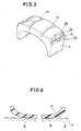
- the outer periphery of the tread region that is, the tread surface is formed in a smoothly curved profile all over the width. Accordingly, as exaggeratedly shown in Fig.6, the tread surface A has non-contacting parts D in the vicinity of the tread edges.
- Such part is gradually apart from the road surface C towards the axially outside owing to the above-mentioned curvature, but its start point b is always shifted irregularly while running on the road having various gradients on the road surface, which makes irregular lateral force on the tire, and the force acts on the rigid tread edge portions. As the result, the wandering phenomenon of the vehicle is induced.
- the present invention was made.
- an object of the present invention to provide a heavy duty radial tire by which the wandering phenomenon can be effectively prevented.
- a heavy duty radial tire has a tread surface defining a ground contacting area between the axially outer edges thereof and provided with at least one longitudinal groove extending in the circumferential direction of the tire, and a buffer plane extended radially inwardly from each of the axially outer edges of the tread surface so as to be formed substantially in part of a right circular corn having the axis placed on the tire axis, the buffer plane provided with at least one buffer groove extended substantially continuously in the circumferential direction of the tire.
- the tire 1 for heavy duty vehicles comprises a pair of bead cores one disposed in each bead region, a carcass 7 extended between the bead regions and having a radial cord ply secured in both edge portions to the bead cores, a rubber tread disposed radially outside the carcass, a pair of rubber sidewalls disposed on the outside of the carcass, a belt 9 composed of steel cords and disposed between the carcass and the tread.
- the tire is provided with buffer planes 5 between the axially outer edges 3 of the ground contacting area in the tread region 2 and the radially outer edges 16 of the buttressed part in the sidewall region 4.
- the buttressed part is a radially outward part in the sidewall region.
- the tire is provided in the tread region 2 with four longitudinal grooves 11, 11, 12 and 12 extended zigzag in the circumferential direction of the tire to form a rib type tread pattern which is made up of five ribs, one center rib 13 between the inner two longitudinal grooves 11, two middle ribs 14 between the inner longitudinal groove 11 and the outer longitudinal groove 12, and two outer ribs 15 between the outer longitudinal groove 12 and the edge 3 of the ground contacting area.
- the edges of the ground contacting area of the conventional radial tire lies between the tread edge and a position 5 % distance of the tire section width axially inward thereof when the tire is mounted on a specified rim and inflated at a design pressure at a rated load.
- the buffer plane can be formed by cutting off the tread edge portions of such tire outward of the edges of the ground contacting area
- the buffer plane 5 is formed in part of a right cylindrical cone having the axis placed on the tire axis. Accordingly, in a section including the tire axis, the buffer plane 5 presents a straight line, but a mild curved line such as a concave or a convex which is regarded as being substantially straight can be also employed. In a section including the tire axis, the length b along the buffer plane 5 is more than 0.05 times and less than 0.18 times, more preferably less than 0.15 times the axial distance between the edges 3 of the ground contacting area.
- the inclination (alfa) of the buffer plane 5 is less than 70 degrees, and more preferably less than 55 degrees and more than 25 degrees, where the inclination is defined, in a tire section including the tire axis, as an angle between a straight line (5) drawn between the above-mentioned edges 3 and 16 and a straight line Y1 drawn radially inwardly from the edge 3 in parallel with the tire equator.
- the buffer plane 5 is grooved in the circumferential direction of the tire to form at least one buffer groove, in this embodiment two grooves 20, 21.
- the width W of the buffer grooves is about 0.5 to 7 mm.
- the depth C of the buffer grooves is more than 0.25 times and less than 0.8 times, and more preferably more than 0.3 times the depth d of the above-mentioned longitudinal grooves, where the depth is defined as a distance of the groove base from the buffer plane 5, that is, a length measured at right angle to the buffer plane 5 from the groove base to the buffer plane 5.
- the inclination (beta) of each buffer groove is more than - 15 degrees and less than 45 degrees, and more preferably more than -10 degrees, where the inclination is defined as an angle between the center line X of the buffer groove and a straight line drawn radially inwardly from the point of intersection of the line X and the plane 5 in parallel with the tire equator, and the negative indicates an axially inward inclination as shown in Fig.2 and accordingly, the positive indicates an axially outward inclination.
- the above-mentioned buffer plane 5 is provided with sipes 24.
- the sipes are extended axially inwardly from the buffer groove adjacent to the edge 3, in this example the groove 21, beyond the edge 3 into the ground contacting area, and the length of the slips is set so that the distance of the axially inner end thereof from the edge 3 becomes about 3 to 15 mm.
- the sipes are arranged circumferentially of the tire at intervals of 5 to 20 mm, that is, the circumferential pitch of the sipes is set to be about 5 to 20 mm to decrease the rigidity of the portion around the edge 3 with preventing that portion from being torn off and being cracked.
- the width W and the depth c of the buffer grooves were 4.0 mm and 8.0 mm, respectively.
- the inclination (beta) of the center line X of the buffer groove was 10 degrees.
- the circumferential pitch of the sipes was about 15 mm.
- the length l was 10 mm, and the depth of the sipe was the same as that of the buffer grooves.
- the tires of each kind were mounted on all of the wheels of a 11-ton truck, and the truck was so loaded that the load of each tire become a normal one (2425 kg), and then the truck run on such a road that the wandering phenomenon is apt to occur at 80 km/h.
- the tire of each kind were evaluated on the wandering phenomenon by three drivers' feelings on the basis of the assumption that the evaluation for a conventional tire is 3.0.
- the three drivers' evaluations are averaged, and it is given in Table 1, wherein the larger the number, the better the result is. Further, the results set out in Table 1 are plotted in Fig.4, wherein the evaluation is classified into six ranks as shown in Fig.4.
- Table 1 and Fig.4 are apparently shows that the tires in a specific area surrounded by a chain line are superior to the conventional tire.
- Such area ranges from 25 to 70 degrees (more preferably 25 to 55 degrees) in the inclination (alfa) and, in the length b, from 0.05 to 0.18 times (more preferably 0.05 to 0.15 times) the length a.
- the length b of the buffer plane 5 is less than 0.05 times, it's effect could not be disposed, and if it is more than 0.18 times, the rigidity of the edge part 3 would become increased.
- the inclination angle is less than 25 degrees, the rigidity of the above-mentioned edge part becomes excessively low, and if it is more than 70 degrees, there is a possibility that the buffer plane 5 contact with ground.
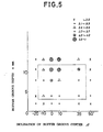
- test tires were manufactured with changing the depth c and the inclination (beta) of the buffer grooves 20, 21, and evaluated.
- the results are given in Table 2 and plotted in Fig.5.
- the length b of the buffer plane 5 was 18 mm, that is, o.1 times the length (a), the inclination (alfa) thereof was 55 degrees, and the depth d of the longitudinal grooves was 13.3 mm.
- 2.0 mm, 4.0 mm and 13.3 mm depth in the buffer groove correspond to 0.15 times, 0.3 times and 1.0 times the depth d of the longitudinal groove.
- the tires superior to the conventional tire are in a specific area as indicated by a chain line in Fig.5.
- Such area ranges from -15 to 45 degrees (more preferably -10 to 45 degrees) in the inclination angle, and, in the groove depth c, ranges from 0.25 to 0.8 times (more preferably 0.3 to 0.8 times) the depth c of the longitudinal groove.
- the groove depth c is less than 0.25 times the depth d, the rigidity of the edge part can not be lowered, and when the groove depth c is 1.0 time the depth d, the occurrence of cracks in the groove base of the buffer groove was observed in the running tests.
- the depth of buffer groove 20, 21 is limited to less than 0.8 times the depth d of the lingitudinal groove. It is though that the inclination angle (beta) has much effect on the rigidity of the edge part.
- the tires included one provided with one buffer groove extending at the center of the buffer plane 5, one provided with parallel two buffer grooves, and one provided with parallel three buffer grooves, wherein each groove has the same width of 4 mm.
- the length a between the edges 3 of the ground contacting area was 180 mm
- the length b of the buffer plane 5 was 18 mm
- the groove depth c of the buffer groove was 8.0 mm
- the inclination angle (beta) thereof was 0 degree.
- the tires of each kind were mounted on the front wheels of a 11-ton truck, and the truck run on such a road that the wandering phenomenon is apt to occur at 80 km/h.
- Fig.3 shows a tire of a rib-rug type tread pattern for another embodiment of the present invention, wherein each buffer plan 5 is provided with one buffer groove 20, and lug grooves 25 are extended axially from each buffer plan 5 to the ground contacting area across the buffer groove, and the sipes 24 extended axially inwardly from the buffer groove 20 are also provided between the circumferentially adjacent two lug grooves. Even in such case that the buffer groove is crossed by another groove such as the lug groove 25 of Fig.3, the buffer groove is substantially continuous in the circumferential direction of the tire though such groove.
- the tire is provided with the buffer planes extended radially inwardly one from each edge of the ground contacting area. Accordingly, even when the ground surface has various inclinations in the lateral direction with respect to the running direction, the tire can always contact with the ground at a certain portion between the edges of the ground contacting area because the unfixed non-contacting portions has been previously removed. As the result, the variation of the width and shape of the ground contacting ares is suppressed, and the occurences of wandering phenomenon are lessened. Furthermore, each buffer plane is provided with at least one buffer groove, whereby the rigidity of the edge portions of the tread is lowered.
- the edge portion damps the force acting thereon from the road surface inclinations, which further lessen the occurences of wandering phenomenon. Still furthermore, if the sipes are formed in the edge portions, the vending rigidity of those portions would become low, and the fitness to the road is improved, which would alleviate not only the wandering phenomenon but also the tread edge wear.
Landscapes
- Engineering & Computer Science (AREA)
- Mechanical Engineering (AREA)
- Tires In General (AREA)
Applications Claiming Priority (2)
| Application Number | Priority Date | Filing Date | Title |
|---|---|---|---|
| JP312682/87 | 1987-12-09 | ||
| JP62312682A JP2573264B2 (ja) | 1987-12-09 | 1987-12-09 | 重荷重用ラジアルタイヤ |
Publications (3)
| Publication Number | Publication Date |
|---|---|
| EP0319860A2 true EP0319860A2 (fr) | 1989-06-14 |
| EP0319860A3 EP0319860A3 (en) | 1989-12-06 |
| EP0319860B1 EP0319860B1 (fr) | 1992-02-26 |
Family
ID=18032154
Family Applications (1)
| Application Number | Title | Priority Date | Filing Date |
|---|---|---|---|
| EP88120189A Expired EP0319860B1 (fr) | 1987-12-09 | 1988-12-02 | Bandage pneumatique pour véhicules poids lourds |
Country Status (5)
| Country | Link |
|---|---|
| US (1) | US4993466A (fr) |
| EP (1) | EP0319860B1 (fr) |
| JP (1) | JP2573264B2 (fr) |
| CA (1) | CA1334373C (fr) |
| DE (1) | DE3868601D1 (fr) |
Cited By (4)
| Publication number | Priority date | Publication date | Assignee | Title |
|---|---|---|---|---|
| EP1184206A1 (fr) * | 2000-08-31 | 2002-03-06 | The Goodyear Tire & Rubber Company | Bandage pneumatique pour poids-lourds |
| EP1400375A3 (fr) * | 2002-09-19 | 2004-03-31 | The Goodyear Tire & Rubber Company | Pneumatique pour essieu directeur de camion, moule et procédé de moulage |
| EP1970220A1 (fr) * | 2007-03-15 | 2008-09-17 | Sumtiomo Rubber Industries Ltd | Pneu |
| DE10357787B4 (de) * | 2003-07-10 | 2010-10-14 | Hyundai Motor Company | Überschlagschutzsystem für ein Fahrzeug |
Families Citing this family (14)
| Publication number | Priority date | Publication date | Assignee | Title |
|---|---|---|---|---|
| JPH04310406A (ja) * | 1991-04-08 | 1992-11-02 | Yokohama Rubber Co Ltd:The | 重荷重用空気入りラジアルタイヤ |
| JP2643066B2 (ja) * | 1991-11-21 | 1997-08-20 | 住友ゴム工業株式会社 | 空気入りタイヤ |
| AU118149S (en) | 1993-02-11 | 1993-09-02 | Airboss Ltd | Tyre element |
| AU118148S (en) | 1993-02-11 | 1993-09-02 | Airboss Ltd | Tyre element |
| JP3344794B2 (ja) * | 1993-12-15 | 2002-11-18 | 横浜ゴム株式会社 | 空気入りラジアルタイヤ |
| AU738228B2 (en) * | 1996-12-19 | 2001-09-13 | Michelin Recherche Et Technique S.A. | Sacrificial ribs for improved tire wear |
| JP4878707B2 (ja) * | 2001-07-25 | 2012-02-15 | 東洋ゴム工業株式会社 | 重荷重用空気入りラジアルタイヤ |
| US20040112493A1 (en) * | 2002-12-13 | 2004-06-17 | Warchol Thomas Stephen | Truck steer tire |
| JP4630761B2 (ja) * | 2005-08-23 | 2011-02-09 | 株式会社ブリヂストン | 重荷重タイヤ |
| JP4813230B2 (ja) * | 2006-03-29 | 2011-11-09 | 東洋ゴム工業株式会社 | 空気入りタイヤ |
| DE602007011184D1 (de) * | 2006-10-31 | 2011-01-27 | Kumho Tire Co Inc | Radialluftreifen mit Wasserleitrippe |
| JP5606847B2 (ja) * | 2010-09-16 | 2014-10-15 | 東洋ゴム工業株式会社 | 空気入りタイヤ |
| JP6766460B2 (ja) * | 2016-06-15 | 2020-10-14 | 住友ゴム工業株式会社 | 空気入りタイヤ |
| JP7641115B2 (ja) * | 2020-12-24 | 2025-03-06 | Toyo Tire株式会社 | 空気入りタイヤ |
Family Cites Families (9)
| Publication number | Priority date | Publication date | Assignee | Title |
|---|---|---|---|---|
| CH25535A (de) * | 1902-03-26 | 1903-05-31 | Thomas Schuh | Parallelschraubstock |
| GB527015A (en) * | 1939-02-27 | 1940-10-01 | Dunlop Rubber Co | Improvements in treads for pneumatic tyres |
| GB819553A (en) * | 1957-01-31 | 1959-09-02 | Pirelli | Improvements in or relating to pneumatic tyres for vehicle wheels |
| US3097681A (en) * | 1960-01-25 | 1963-07-16 | Carlyle M Harkins | Tire |
| NL301083A (fr) * | 1962-12-11 | |||
| DE1480933A1 (de) * | 1964-03-26 | 1969-04-17 | Continental Gummi Werke Ag | Laufflaechenprofilierung fuer Fahrzeugluftreifen |
| JPS5544028A (en) * | 1978-09-21 | 1980-03-28 | Bridgestone Corp | Radial tire for heavy car |
| JPS577703A (en) * | 1980-06-17 | 1982-01-14 | Bridgestone Corp | Pneumatic radial tire with reduced rolling resistance |
| JPS60189609A (ja) * | 1984-03-07 | 1985-09-27 | Sumitomo Rubber Ind Ltd | 重車両用ラジアルタイヤ |
-
1987
- 1987-12-09 JP JP62312682A patent/JP2573264B2/ja not_active Expired - Fee Related
-
1988
- 1988-12-02 DE DE8888120189T patent/DE3868601D1/de not_active Expired - Fee Related
- 1988-12-02 EP EP88120189A patent/EP0319860B1/fr not_active Expired
- 1988-12-05 US US07/279,708 patent/US4993466A/en not_active Expired - Lifetime
- 1988-12-06 CA CA000585116A patent/CA1334373C/fr not_active Expired - Fee Related
Cited By (6)
| Publication number | Priority date | Publication date | Assignee | Title |
|---|---|---|---|---|
| EP1184206A1 (fr) * | 2000-08-31 | 2002-03-06 | The Goodyear Tire & Rubber Company | Bandage pneumatique pour poids-lourds |
| EP1400375A3 (fr) * | 2002-09-19 | 2004-03-31 | The Goodyear Tire & Rubber Company | Pneumatique pour essieu directeur de camion, moule et procédé de moulage |
| DE10357787B4 (de) * | 2003-07-10 | 2010-10-14 | Hyundai Motor Company | Überschlagschutzsystem für ein Fahrzeug |
| EP1970220A1 (fr) * | 2007-03-15 | 2008-09-17 | Sumtiomo Rubber Industries Ltd | Pneu |
| US7832439B2 (en) | 2007-03-15 | 2010-11-16 | Sumitomo Rubber Industries, Ltd. | Pneumatic tire having recess in buttress face |
| CN101264720B (zh) * | 2007-03-15 | 2012-01-25 | 住友橡胶工业株式会社 | 充气轮胎 |
Also Published As
| Publication number | Publication date |
|---|---|
| EP0319860B1 (fr) | 1992-02-26 |
| JP2573264B2 (ja) | 1997-01-22 |
| JPH01153303A (ja) | 1989-06-15 |
| US4993466A (en) | 1991-02-19 |
| DE3868601D1 (de) | 1992-04-02 |
| CA1334373C (fr) | 1995-02-14 |
| EP0319860A3 (en) | 1989-12-06 |
Similar Documents
| Publication | Publication Date | Title |
|---|---|---|
| EP0319860B1 (fr) | Bandage pneumatique pour véhicules poids lourds | |
| EP2202096B1 (fr) | Pneu | |
| EP0841199B1 (fr) | Bandage pneumatique | |
| US5407005A (en) | Tread for a tire | |
| US4977942A (en) | Pneumatic tire having defined lug groove configuration | |
| US4798236A (en) | High performance tire tread | |
| US4736783A (en) | Heavy load pneumatic radial tire | |
| EP0878329B1 (fr) | Bandage pneumatique poru poids-lourds | |
| EP0602989A1 (fr) | Bandage pneumatique | |
| US7918256B2 (en) | Heavy duty tire having ground contacting face at 70% and 100% maximum tire load | |
| EP0461858B1 (fr) | Pneumatique pour charges lourdes | |
| US4756352A (en) | Pneumatic tire tread with divided shoulder | |
| EP0728599B1 (fr) | Bandage pneumatique | |
| US6371179B1 (en) | Pneumatic tire including shoulder blocks | |
| US4739812A (en) | Pneumatic tire tread with recessed shoulder portion | |
| US4567929A (en) | Bias ply pneumatic tire tread with lateral notches | |
| EP1207056B1 (fr) | Bandage pneumatique avec une forme d'empreinte au sol s'adaptant au poids à supporter | |
| EP0676305B1 (fr) | Bandage pneumatique | |
| US5524686A (en) | Heavy duty tire including narrow circumferential grooves | |
| US20040134581A1 (en) | Pneumatic tire | |
| JP3467084B2 (ja) | 空気入りラジアルタイヤ | |
| GB2343159A (en) | Pneumatic tyre tread portion | |
| EP3988331B1 (fr) | Bandage pneumatique | |
| JPH09240216A (ja) | 空気入りラジアルタイヤ | |
| GB2253816A (en) | Pneumatic tire tread having high density siping zones in the shoulder regions |
Legal Events
| Date | Code | Title | Description |
|---|---|---|---|
| PUAI | Public reference made under article 153(3) epc to a published international application that has entered the european phase |
Free format text: ORIGINAL CODE: 0009012 |
|
| AK | Designated contracting states |
Kind code of ref document: A2 Designated state(s): DE FR GB |
|
| PUAL | Search report despatched |
Free format text: ORIGINAL CODE: 0009013 |
|
| AK | Designated contracting states |
Kind code of ref document: A3 Designated state(s): DE FR GB |
|
| 17P | Request for examination filed |
Effective date: 19900213 |
|
| 17Q | First examination report despatched |
Effective date: 19910516 |
|
| GRAA | (expected) grant |
Free format text: ORIGINAL CODE: 0009210 |
|
| AK | Designated contracting states |
Kind code of ref document: B1 Designated state(s): DE FR GB |
|
| REF | Corresponds to: |
Ref document number: 3868601 Country of ref document: DE Date of ref document: 19920402 |
|
| ET | Fr: translation filed | ||
| PLBE | No opposition filed within time limit |
Free format text: ORIGINAL CODE: 0009261 |
|
| STAA | Information on the status of an ep patent application or granted ep patent |
Free format text: STATUS: NO OPPOSITION FILED WITHIN TIME LIMIT |
|
| 26N | No opposition filed | ||
| REG | Reference to a national code |
Ref country code: GB Ref legal event code: IF02 |
|
| PGFP | Annual fee paid to national office [announced via postgrant information from national office to epo] |
Ref country code: GB Payment date: 20031126 Year of fee payment: 16 |
|
| PGFP | Annual fee paid to national office [announced via postgrant information from national office to epo] |
Ref country code: FR Payment date: 20031210 Year of fee payment: 16 |
|
| PGFP | Annual fee paid to national office [announced via postgrant information from national office to epo] |
Ref country code: DE Payment date: 20031211 Year of fee payment: 16 |
|
| PG25 | Lapsed in a contracting state [announced via postgrant information from national office to epo] |
Ref country code: GB Free format text: LAPSE BECAUSE OF NON-PAYMENT OF DUE FEES Effective date: 20041202 |
|
| PG25 | Lapsed in a contracting state [announced via postgrant information from national office to epo] |
Ref country code: DE Free format text: LAPSE BECAUSE OF NON-PAYMENT OF DUE FEES Effective date: 20050701 |
|
| GBPC | Gb: european patent ceased through non-payment of renewal fee |
Effective date: 20041202 |
|
| PG25 | Lapsed in a contracting state [announced via postgrant information from national office to epo] |
Ref country code: FR Free format text: LAPSE BECAUSE OF NON-PAYMENT OF DUE FEES Effective date: 20050831 |
|
| REG | Reference to a national code |
Ref country code: FR Ref legal event code: ST |