EP0320277B1 - Bildherstellung mit Hervorhebung der Farben - Google Patents
Bildherstellung mit Hervorhebung der Farben Download PDFInfo
- Publication number
- EP0320277B1 EP0320277B1 EP88311669A EP88311669A EP0320277B1 EP 0320277 B1 EP0320277 B1 EP 0320277B1 EP 88311669 A EP88311669 A EP 88311669A EP 88311669 A EP88311669 A EP 88311669A EP 0320277 B1 EP0320277 B1 EP 0320277B1
- Authority
- EP
- European Patent Office
- Prior art keywords
- developer
- development
- voltage
- charge
- image
- Prior art date
- Legal status (The legal status is an assumption and is not a legal conclusion. Google has not performed a legal analysis and makes no representation as to the accuracy of the status listed.)
- Expired - Lifetime
Links
- 238000003384 imaging method Methods 0.000 title description 10
- 238000000034 method Methods 0.000 claims description 17
- 230000000694 effects Effects 0.000 claims description 6
- 238000011086 high cleaning Methods 0.000 claims description 6
- 230000002411 adverse Effects 0.000 claims description 3
- 230000000704 physical effect Effects 0.000 claims 2
- 108091008695 photoreceptors Proteins 0.000 description 26
- 239000000463 material Substances 0.000 description 18
- 238000004140 cleaning Methods 0.000 description 9
- 239000002245 particle Substances 0.000 description 8
- 239000000843 powder Substances 0.000 description 6
- 230000008569 process Effects 0.000 description 5
- 239000003086 colorant Substances 0.000 description 3
- 239000000758 substrate Substances 0.000 description 3
- 239000011324 bead Substances 0.000 description 2
- 230000000295 complement effect Effects 0.000 description 2
- 230000005684 electric field Effects 0.000 description 2
- 230000005686 electrostatic field Effects 0.000 description 2
- 230000007246 mechanism Effects 0.000 description 2
- 230000005855 radiation Effects 0.000 description 2
- 239000007787 solid Substances 0.000 description 2
- 238000006424 Flood reaction Methods 0.000 description 1
- 230000003213 activating effect Effects 0.000 description 1
- 238000000418 atomic force spectrum Methods 0.000 description 1
- 230000008901 benefit Effects 0.000 description 1
- 230000015572 biosynthetic process Effects 0.000 description 1
- 239000002131 composite material Substances 0.000 description 1
- 239000011810 insulating material Substances 0.000 description 1
- 150000002500 ions Chemical class 0.000 description 1
- 239000000203 mixture Substances 0.000 description 1
- 230000003287 optical effect Effects 0.000 description 1
- 238000009877 rendering Methods 0.000 description 1
- 230000004044 response Effects 0.000 description 1
- 230000002000 scavenging effect Effects 0.000 description 1
- 239000007921 spray Substances 0.000 description 1
- 230000007704 transition Effects 0.000 description 1
Images


Classifications
-
- G—PHYSICS
- G03—PHOTOGRAPHY; CINEMATOGRAPHY; ANALOGOUS TECHNIQUES USING WAVES OTHER THAN OPTICAL WAVES; ELECTROGRAPHY; HOLOGRAPHY
- G03G—ELECTROGRAPHY; ELECTROPHOTOGRAPHY; MAGNETOGRAPHY
- G03G13/00—Electrographic processes using a charge pattern
- G03G13/01—Electrographic processes using a charge pattern for multicoloured copies
- G03G13/013—Electrographic processes using a charge pattern for multicoloured copies characterised by the developing step, e.g. the properties of the colour developers
-
- G—PHYSICS
- G03—PHOTOGRAPHY; CINEMATOGRAPHY; ANALOGOUS TECHNIQUES USING WAVES OTHER THAN OPTICAL WAVES; ELECTROGRAPHY; HOLOGRAPHY
- G03G—ELECTROGRAPHY; ELECTROPHOTOGRAPHY; MAGNETOGRAPHY
- G03G13/00—Electrographic processes using a charge pattern
- G03G13/06—Developing
- G03G13/08—Developing using a solid developer, e.g. powder developer
- G03G13/09—Developing using a solid developer, e.g. powder developer using magnetic brush
-
- G—PHYSICS
- G03—PHOTOGRAPHY; CINEMATOGRAPHY; ANALOGOUS TECHNIQUES USING WAVES OTHER THAN OPTICAL WAVES; ELECTROGRAPHY; HOLOGRAPHY
- G03G—ELECTROGRAPHY; ELECTROPHOTOGRAPHY; MAGNETOGRAPHY
- G03G15/00—Apparatus for electrographic processes using a charge pattern
- G03G15/01—Apparatus for electrographic processes using a charge pattern for producing multicoloured copies
- G03G15/0105—Details of unit
- G03G15/0121—Details of unit for developing
Definitions
- This invention relates generally to the rendering of latent electrostatic images visible using multiple colors of dry toner or developer and, more particularly, to an image forming method including structure for suppressing the development of the fringe fields of complementary tri-level images while developing acceptable line images, notwithstanding the presence of relatively high cleaning fields.
- the invention can be utilized in the art of xerography or in printing.
- conventional xerography it is the general procedure to form electrostatic latent images on a xerographic surface by first uniformly charging a photoconductive insulating surface or photoreceptor.
- the charge is selectively dissipated in accordance with a pattern of activating radiation corresponding to original images.
- the selective dissipation of the charge leaves a latent charge pattern on the imaging surface corresponding to the areas not struck by radiation.
- This charge pattern is made visible by developing it with toner.
- the toner is generally a colored powder which adheres to the charge pattern by electrostatic attraction.
- the developed image is then fixed to the imaging surface or is transferred to a receiving substrate such as plain paper to which it is fixed by suitable fusing techniques.
- the charge pattern is developed with toner particles of first and second colors.
- the toner particles of one of the colors are positively charged, and the toner particles of the other color are negatively charged.
- the toner particles are supplied by a developer which comprises a mixture of triboelectrically relatively-positive and relatively-negative carrier beads.
- the carrier beads support the relatively negative and relatively positive toner particles.
- Such a developer is generally supplied to the charge pattern by cascading it across the imaging surface supporting the charge pattern.
- the toner particles are presented to the charge pattern by a pair of magnetic brushes. Each brush supplies a toner of one color and one charge.
- the development system is biased to about the background voltage. Such biasing results in a developed image of improved color sharpness.
- the xerographic contrast on the charge-retentive surface or photoreceptor is divided three, rather than two, ways, as is the case in conventional xerography.
- the photoreceptor is charged, typically to 900V. It is exposed imagewise, such that one image corresponding to charged image areas (which are subsequently developed by charged area development, i.e. CAD) stays at the full photoreceptor potential (V ddp or V cad, see Figures 1a and 1b).
- the other image is exposed to discharge the photoreceptor to its residual potential, i.e. V c or V dad (typically 100v) which corresponds to discharged area images that are subsequently developed by discharged-area development (DAD).
- V c or V dad typically 100v
- the background areas are exposed such as to reduce the photoreceptor potential to halfway between the V cad and V dad potentials, (typically 500V) and is referred to as V w or V white .
- the CAD developer is typically biased about 100V closer to V cad than V white (about 600V),and the DAD developer system is biased about 100V closer to V dad than V white (about 400V).
- magnetic brushes have been designed to give fringe - field or solid-area development by adjusting the conductivity of the carrier. It is also stated therein that they can also be made to tone areas of less charge, and clean areas of greater charge giving what is known in the art as a reverse development.
- conductive magnetic brush (CMB) development and insulating magnetic brush (IMB) development systems suffer from limitations in their abilities to meet the full range of copy quality requirements.
- insulating magnetic brush development systems have difficulty in using one developer roller to develop both fine-lines and solid areas.
- the spacing between the developer roller and photoconductive surface must be made quite small.
- low-density fine-line development occurs at a larger spacing to take advantage of the accuracy of fringe-field development with insulating materials. This permits development with high cleaning fields so as to minimize background development.
- conductive magnetic brush development systems inherently fail to reproduce low density lines faithfully.
- Conductive developer materials are not sensitive to fringe fields.
- the cleaning field In order to achieve low-density fine-line development with conductive developer materials, the cleaning field must be relatively low. This produces relatively high background.
- the images comprise charged-area images and discharged-area images. Such images are commonly referred to as charged area development (CAD) images and discharged area development images, respectively.
- CAD charged area development
- DAD discharged area development
- the CAD image is developed using a charged area development (CAD) system including a positive black toner, with subsequent development of the discharged area using a discharged area development (DAD) system including a negative colored toner.
- CAD charged area development
- DAD discharged area development
- V white background
- the magnitude of the field is determined by the difference between the voltage level of the CAD image after development which is approximately equal to the CAD bias voltage V bb ( Figure 1b) ,or the background, V white and the bias voltage on the discharged area development (DAD) system which is V cb .
- the field thus established tends to cause the negative toner to migrate away from the photoreceptor towards the developer rolls.
- the development field generated by the fine-line doesn't have time to attract enough toner that has drifted away from the photoreceptor surface into the developer back to the charge-retentive surface to develop the DAD fine-line image adequately.
- toner's inertia Because of the toner's inertia, it takes a finite time for the toner to move in response to a rapidly changing development field, and in the case of a fine-line, perpendicular to the process direction, there may not be sufficient time if the toner has migrated too far into the developer. Thus, line images may be improperly developed. This phenomenon is known as a developer history effect, which in this case is manifest as an underdeveloped fine-line.
- fringe fields are caused by the reverse development or cleaning fields established between the developer biases and a complementary image (either developed or latent) on the charge-retentive surface.
- the colored border around the black image results from the field established because of the difference (
- the present invention uses a magnetic brush developer apparatus comprising a plurality of developer housings each including a plurality of magnetic rolls associated therewith.
- Conductive magnetic brush (CMB) developer is provided in each of the developer housings.
- the CMB developer is used to develop electronically formed images.
- the developer conductivity as measured in a Gutman conductivity cell, is in the range of 10 ⁇ 9 to 10-13 (ohm-cm) ⁇ 1.
- the toner concentration of the developer is 2.0 to 3.0% by weight and the charge level is less than 20 microcoulombs/gram.
- the developer rolls are spaced from the charge-retentive surface a distance in the order of 1.0 to 3.0 mm.
- FIG. 1a illustrates the tri-level electrostatic latent image in more detail.
- V o is the initial charge level
- V ddp the dark discharge potential (unexposed)
- V w the white discharge level
- V c the photoreceptor residual potential (full exposure).
- Color discrimination in the development of the electrostatic latent image is achieved by passing the photoreceptor through two developer housings in tandem, which housings are electrically biased to voltages which are offset from the background voltage V w , the direction of offset depending on the polarity or sign of toner in the housing.
- One housing (for the sake of illustration, the first) contains developer with black toner having triboelectric properties such that the toner is driven to the most highly charged (V ddp ) areas of the latent image by the electric field between the photoreceptor and the development rolls biased at V bb (V black bias) as shown in Figure 1b.
- the triboelectric charge on the colored toner in the second housing is chosen so that the toner is urged towards parts of the latent image at residual potential, V c by the electric field existing between the photoreceptor and the development rolls in the second housing at bias voltage V cb (V color bias).
- a charge-retentive member in the form of a photoconductive belt 10 consisting of a photoconductive surface and an electrically conductive substrate and mounted for movement past a charging station A, an exposure B, developer stations C, transfer station D and cleaning station F.
- Belt 10 moves in the direction of arrow 16 to advance successive portions thereof sequentially through the various processing stations disposed about the path of movement thereof.
- Belt 10 is entrained about a plurality of rollers 18,20 and 22, the former of which can be used as a drive roller and the latter of which can be used to provide suitable tensioning of the photoreceptor belt 10.
- Motor 23 rotates roller 18 to advance belt 10 in the direction of arrow 16.
- Roller 18 is coupled to motor 23 by suitable means such as a belt drive.
- a corona discharge device such as a scorotron, corotron or dicorotron 24 charges the belt 10 to a selectively high uniform positive or negative potential, V o .
- V o uniform positive or negative potential
- Any suitable control may be employed for controlling the corona discharge device 24.
- the charged portions of the photoreceptor surface are advanced through exposure station B.
- the uniformly-charged photoreceptor or charge-retentive surface 10 is exposed to a laser based input and/or output scanning device 25 which causes the charge-retentive surface to be discharged in accordance with the output from the scanning device.
- the scanning device is a three-level laser raster output scanner (ROS).
- the ROS output is set via a programmable power supply which is driven by means of a controller via a digital-to-analog converter.
- the ROS could be replaced by a conventional xerographic exposure device.
- the photoreceptor which is initially charged to a voltage Vo, undergoes dark decay to a level V ddp .
- V w imagewise in the background (white) image areas
- V c near zero or ground potential in the highlight (i.e. color other than black) color parts of the image. See Figure 1a.
- a magnetic brush development system 30 advances developer materials into contact with the electrostatic latent images.
- the development system 30 comprises first and second developer housings 32 and 34.
- each magnetic brush development housing includes a pair of magnetic brush developer rollers.
- the housing 32 contains a pair of rollers 35, 36
- the housing 34 contains a pair of magnetic brush rollers 37,38.
- Each pair of rollers advances its respective developer material into contact with the latent image.
- Appropriate developer biasing is accomplished via power supplies 41 and 43 electrically connected to respective developer housings 32 and 34.
- Color discrimination in the development of the electrostatic latent image is achieved by passing the photoreceptor past the two developer housings 32 and 34 in a single pass, with the magnetic brush rolls 35,36,37 and 38 electrically biased to voltages which are offset from the background voltage V w , the direction of offset depending on the polarity of toner in the housing.
- One housing e.g. 32 (for the sake of illustration, the first) contains developer with black toner 40 having triboelectric properties such that the toner is driven to the most highly charged (V ddp ) areas of the latent image by the electrostatic field (development field) between the photoreceptor and the development rolls biased at V bb as shown in Figure 1b.
- the triboelectric charge on colored toner 42 in the second housing is chosen so that the toner is urged towards parts of the latent image at residual potential, V c by the electrostatic field (development field) existing between the photoreceptor and the development rolls in the second housing at bias voltages V cb .
- good quality images including line images were produced using developers 40 and 42 which comprise conductive magnetic brush (CMB) developer material with a conductivity in the range of 10 ⁇ 9 to 10-13 (ohm-cm) ⁇ 1.
- These developers comprise an insulative toner and a conductive carrier, the conductivity of the carrier being in the order of 10 ⁇ 9 to 10 ⁇ 10 (ohm-cm) ⁇ 1.
- the toner concentration of the developers 40 and 42 is in the order of 2.0 to 3.0% by weight and the charge level is less than 20 microcoulombs/gram.
- the developer rolls were spaced from the charge-retentive surface in the order of 1.0 to 3.0 mm.
- the entire photoreceptor voltage difference (
- a sheet of support material 58 is moved into contact with the toner image at transfer station D.
- the sheet of support material is advanced to transfer station D by conventional sheet-feeding apparatus, not shown.
- sheet-feeding apparatus includes a feed roll contacting the uppermost sheet of a stack of copy sheets. Feed rolls rotate so as to advance the uppermost sheet from the stack into a chute which directs the advancing sheet of support material into contact with photoconductive surface of belt 10 in a timed sequence so that the toner powder image developed thereon contacts the advancing sheet of support material at transfer station D.
- a pre-transfer corona discharge member 56 is provided to condition the toner for effective transfer to a substrate using corona discharge.
- Transfer station D includes a corona-generating device 60 which sprays ions of a suitable polarity onto the back of sheet 58. This attracts the charged toner powder images from the belt 10 to sheet 58. After transfer, the sheet continues to move, in the direction of arrow 62, onto a conveyor (not shown) which advances the sheet to fusing station E.
- Fusing station E includes a fuser assembly 64, which permanently affixes the transferred powder image to sheet 58.
- fuser assembly 64 comprises a heated fuser roller 66 and a backup roller 68.
- Sheet 58 passes between fuser roller 66 and backup roller 68 with the toner powder image contacting fuser roller 66. In this manner, the toner powder image is permanently affixed to sheet 58.
- a chute guides the advancing sheet 58 to a catch tray, also not shown, for subsequent removal by the operator.
- the residual toner particles carried by the non-image areas on the photoconductive surface are removed therefrom. These particles are removed at cleaning station F.
- a discharge lamp (not shown) floods the photoconductive surface with light to dissipate any residual electrostatic charge remaining prior to the charging thereof for the successive imaging cycle.
- the magnetic brush rolls 35 and 36 may comprise any structures that provide a magnetic field that forms the developer material in the housing 32 into a brush-like configuration in the development zone between the rolls 35 and 36 and the charge-retentive surface. This arrangement effects development of one of the two tri-level images contained on the charge-retentive surface.
- the magnetic brush rolls 37 and 38 are constructed such that development of the other of the two tri-level image is accomplished with minimal disturbance of the first image.
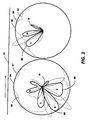
- the magnetic rolls 37 and 38 comprise magnetic force fields as depicted in Figures 3a and 3b, respectively.
- the radial force profiles of the these two rolls are such as to cause developer to be picked up from the developer housing 32 and conveyed to the top of the roll 37 where the developer becomes magnetically unconstrained.
- the developer is moved through the development zone in a magnetically unconstrained manner until it is attracted to the roll 38 because of the radial magnetic forces of that roll.
- Magnetic poles are designated N (north) or S (south).
- the magnetic fields are plotted around the central axis of a two-roll magnetic brush development system such as the one comprising rolls 37,38.
- roll 38 is replicated.
- the rolls are driven synchronously in this example, although it is also possible to have independent drive mechanisms for each roller.
- Figure 3 depicts the radial components, respectively, of the fields of rolls 37 and 38.
- the development system additionally consists of a sump, or reservoir, of magnetic developer material, and optionally a mixing system, paddle wheel, or other apparatus to maintain the developing properties of the material in the sump.
- the developer rolls are rotary non-magnetic cylinders or shells having roughened or longitudinally-corrugated surfaces to urge the developer along by frictional forces around fixed internal magnets.
- the shells are driven synchronously in this example; it is also possible to have independent drive mechanisms for each roller.
- the direction of rotation of the shell around either fixed magnet is counterclockwise as viewed in the drawing.
- the system can also be configured to develop in the clockwise direction with no compromise in performance, depending on the desired properties of the development system with respect to the direction of the photoreceptor (i.e., against-mode or with-mode development).
- the photoreceptor is located above the development rolls.
- the developer materials are transported from left to right from the sump to roll 37, to roll 38, back to the sump.
- a broad radial pole 80 of roll 37 ( Figure 3) positioned at 6 o'clock serves to lift magnetic developer material from a donor roll in the sump or housing 32.
- the developer is moved magnetically unconstrained through the part of the developement zone delineated by the roll 37 and the charge-retentive surface until the developer comes under the influence of a strong radial south pole 86 of the magnet 38. Movement through the aforementioned zone is effected through the cooperation of the charge-retentive surface and the developer shell.
- the pole 86 serves to effect transition of the developer from the roll 37 to the roll 38 without magnetically constraining the developer so as to cause scavenging of the first image as it passes the second developer housing.
- the poles following the pole 86 in the clockwise direction are progressively weaker, so that the developer is magnetically unconstrained as it moves through the part of the development zone delineated by the roll 38 and the charge-retentive surface.
Landscapes
- Physics & Mathematics (AREA)
- General Physics & Mathematics (AREA)
- Color Electrophotography (AREA)
- Magnetic Brush Developing In Electrophotography (AREA)
- Developing For Electrophotography (AREA)
Claims (5)
- Verfahren zum Ausbilden von randfreien Dreipegel-Bildern mit den Schritten:
es wird ein latentes elektrostatisches Dreipegel-Abbild an einer Ladungshaltefläche ausgebildet, wobei das Bild umfaßt eine erste Bildfläche mit einer relativ hohen Spannung, eine zweite Bildfläche bei einer relativ niedrigen Spannung und einen Hintergrundfläche mit einer Spannung in der Mitte zwischen den Pegeln der hohen und der niedrigen Spannung;
ein erster Entwicklerauftrager (32) wird elektrisch auf eine Spannung vorgespannt, die gegenüber der Spannung der Hintergrundfläche in Richtung der hohen Spannung des ersten Bildbereichs abgesetzt ist;
ein zweiter Entwicklerauftrager (34) wird elektrisch auf eie Spannung vorgespannt, die gegen die Spannung der Hintergrundfläche in Richtung der niedrigen Spannung der zweiten Bildfläche abesetzt ist;
der erste Entwicklerauftrager wird benutzt, um auf die Ladungshaltefläche einen ersten leitfähigen magnetischen Bürstenentwickler aufzutragen mit physikalsichen Eigenschaften zum Schwächen der schädlichen Auswirkungen der Entwicklung von feinen Strichen mit niedriger Dichte in der Anwesenheit von hohen Reinigungsfeldern, um die erste Bildfläche mit Toner einer Farbe zu entwickeln; und
der zweite Entwicklerauftrager wird benutzt, um auf die Ladungshaltefläche einen zweiten leitenden Magnetbürsten-Entwickler aufzubringen mit physikalsichen Eigenschaften zum Schwächen der schädlichen Auswirkungen der Entwicklung von feinen Strichen neidriger Dichte in Anwesenheit von hohen Reinigungsfeldern, um die zweite Bildfläche mit Toner einer anderen Farbe zu entwickeln. - Verfahren nach Anspruch 1, bei dem das Aufbringen des ersten und des zweiten Entwicklers den Schritt enthält, daß die Entwicklerauftrager von der Ladungshaltefläche auf einem Abstand im Bereich von 1,0 bis 3,0 mm gehalten werden.
- Verfahren nach Anspruch 1 oder 2, bei dem die Leitfähigkeit des Entwicklers in der Größenordnung von 10⁻⁹ bis 10⁻¹³ (Ohm.cm)⁻¹ liegt.
- Verfahren nach einem der vorangehenden Ansprüche, bei dem der Entwickler ein Zwei-Komponenten-Entwickler ist, dessen Tonerkonzentration in der Größenordnung von 2,0 bis 3,0 Gew.-% liegt.
- Verfahren nach einem der vorangehenden Ansprüche, bei dem der Ladungspegel des Entwicklers kleiner als 20 µC/g ist.
Applications Claiming Priority (2)
| Application Number | Priority Date | Filing Date | Title |
|---|---|---|---|
| US07/132,074 US4847655A (en) | 1987-12-11 | 1987-12-11 | Highlight color imaging apparatus |
| US132074 | 1993-10-04 |
Publications (3)
| Publication Number | Publication Date |
|---|---|
| EP0320277A2 EP0320277A2 (de) | 1989-06-14 |
| EP0320277A3 EP0320277A3 (en) | 1990-09-19 |
| EP0320277B1 true EP0320277B1 (de) | 1993-12-22 |
Family
ID=22452339
Family Applications (1)
| Application Number | Title | Priority Date | Filing Date |
|---|---|---|---|
| EP88311669A Expired - Lifetime EP0320277B1 (de) | 1987-12-11 | 1988-12-09 | Bildherstellung mit Hervorhebung der Farben |
Country Status (4)
| Country | Link |
|---|---|
| US (1) | US4847655A (de) |
| EP (1) | EP0320277B1 (de) |
| JP (1) | JPH01189664A (de) |
| DE (1) | DE3886508T2 (de) |
Families Citing this family (35)
| Publication number | Priority date | Publication date | Assignee | Title |
|---|---|---|---|---|
| US4926199A (en) * | 1988-03-11 | 1990-05-15 | Rastergraphics, Inc. | High resolution electrostatic plotter, printer or the like incorporating a stationary writing head |
| US4879194A (en) * | 1988-05-02 | 1989-11-07 | Xerox Corporation | Tri-level, highlight color imaging using ionography |
| US5038177A (en) * | 1988-12-15 | 1991-08-06 | Xerox Corporation | Selective pre-transfer corona transfer with light treatment for tri-level xerography |
| US5049949A (en) * | 1989-06-29 | 1991-09-17 | Xerox Corporation | Extension of tri-level xerography to black plus 2 colors |
| US5031570A (en) * | 1989-10-20 | 1991-07-16 | Xerox Corporation | Printing apparatus and toner/developer delivery system therefor |
| US5032872A (en) * | 1989-10-30 | 1991-07-16 | Xerox Corporation | Developing device with dual donor rollers including electrically biased electrodes for each donor roller |
| US5080988A (en) * | 1989-11-22 | 1992-01-14 | Xerox Corporation | Biasing scheme for improving latitudes in the tri-level xerographic process |
| DE69015131T2 (de) * | 1989-11-22 | 1995-07-27 | Xerox Corp | Polarisierungsweise zur Verbesserung der Eigenschaften der Drei-Niveau-Xerographie. |
| US5010368A (en) * | 1990-02-20 | 1991-04-23 | Xerox Corporation | Magnetic transport roll for supplying toner or carrier and toner to a donor and magnetic developer roll respectively |
| US5045893A (en) * | 1990-07-02 | 1991-09-03 | Xerox Corporation | Highlight printing apparatus |
| JPH0486750A (ja) * | 1990-07-31 | 1992-03-19 | Konica Corp | カラー画像形成方法 |
| US5204697A (en) * | 1990-09-04 | 1993-04-20 | Xerox Corporation | Ionographic functional color printer based on Traveling Cloud Development |
| US5078087A (en) * | 1991-03-11 | 1992-01-07 | Xerox Corporation | Development apparatus |
| US5223897A (en) * | 1991-09-05 | 1993-06-29 | Xerox Corporation | Tri-level imaging apparatus using different electrostatic targets for cycle up and runtime |
| US5236795A (en) * | 1991-09-05 | 1993-08-17 | Xerox Corporation | Method of using an infra-red densitometer to insure two-pass cleaning |
| US5208632A (en) * | 1991-09-05 | 1993-05-04 | Xerox Corporation | Cycle up convergence of electrostatics in a tri-level imaging apparatus |
| US5227270A (en) * | 1991-09-05 | 1993-07-13 | Xerox Corporation | Esv readings of toner test patches for adjusting ird readings of developed test patches |
| US5138378A (en) * | 1991-09-05 | 1992-08-11 | Xerox Corporation | Electrostatic target recalculation in a xerographic imaging apparatus |
| CA2076791C (en) * | 1991-09-05 | 1999-02-23 | Mark A. Scheuer | Charged area (cad) image loss control in a tri-level imaging apparatus |
| US5132730A (en) * | 1991-09-05 | 1992-07-21 | Xerox Corporation | Monitoring of color developer housing in a tri-level highlight color imaging apparatus |
| US5212029A (en) * | 1991-09-05 | 1993-05-18 | Xerox Corporation | Ros assisted toner patch generation for use in tri-level imaging |
| US5119131A (en) * | 1991-09-05 | 1992-06-02 | Xerox Corporation | Electrostatic voltmeter (ESV) zero offset adjustment |
| US5157441A (en) * | 1991-09-05 | 1992-10-20 | Xerox Corporation | Dark decay control system utilizing two electrostatic voltmeters |
| US5281999A (en) * | 1992-08-24 | 1994-01-25 | Xerox Corporation | Modular highlight color and process color printing machine |
| US5539506A (en) * | 1994-10-31 | 1996-07-23 | Xerox Corporation | Edge raggedness and background removal by post development member |
| JP3236183B2 (ja) * | 1995-01-19 | 2001-12-10 | キヤノン株式会社 | 画像形成装置 |
| US5669049A (en) * | 1995-12-18 | 1997-09-16 | Xerox Corporation | Multi-roll developer housing with converging belt to roll spacing |
| JP3294502B2 (ja) * | 1996-07-24 | 2002-06-24 | 株式会社日立製作所 | 電子写真装置の露光量制御方法 |
| NL1006098C2 (nl) * | 1997-05-21 | 1998-11-25 | Oce Tech Bv | Werkwijze voor het vormen van tonerbeelden in register op een ladingvasthoudend medium alsmede beeldvormende inrichting geschikt voor het uitvoeren van de werkwijze. |
| JP3687824B2 (ja) * | 1997-09-26 | 2005-08-24 | リコープリンティングシステムズ株式会社 | 2色画像形成装置 |
| JP4234667B2 (ja) * | 2004-11-30 | 2009-03-04 | 株式会社東芝 | 移動体用ofdm受信装置 |
| US7312010B2 (en) * | 2005-03-31 | 2007-12-25 | Xerox Corporation | Particle external surface additive compositions |
| US7754408B2 (en) | 2005-09-29 | 2010-07-13 | Xerox Corporation | Synthetic carriers |
| US20080166646A1 (en) * | 2006-10-31 | 2008-07-10 | Xerox Corporation | Toner for reduced photoreceptor wear rate |
| US8676074B2 (en) * | 2011-03-31 | 2014-03-18 | Eastman Kodak Company | Method for providing ratio modulated printing with discharge area development |
Family Cites Families (17)
| Publication number | Priority date | Publication date | Assignee | Title |
|---|---|---|---|---|
| US3457900A (en) * | 1968-02-29 | 1969-07-29 | Eastman Kodak Co | Single magnetic brush apparatus for development of electrostatic images |
| US3702483A (en) * | 1970-12-23 | 1972-11-07 | Xerox Corp | Color rendition method |
| US4398816A (en) * | 1978-08-18 | 1983-08-16 | Fujitsu Limited | Electrophotographic copying printer |
| US4308821A (en) * | 1978-09-22 | 1982-01-05 | Ricoh Company, Ltd. | Electrophotographic development apparatus |
| JPS6032192B2 (ja) * | 1978-11-29 | 1985-07-26 | 株式会社リコー | 3色電子写真複写方法 |
| JPS5583069A (en) * | 1978-12-19 | 1980-06-23 | Hitachi Ltd | Non-impact printer |
| US4397264A (en) * | 1980-07-17 | 1983-08-09 | Xerox Corporation | Electrostatic image development system having tensioned flexible recording member |
| JPS59101657A (ja) * | 1982-12-02 | 1984-06-12 | Minolta Camera Co Ltd | 2色画像形成方法 |
| DE3546358A1 (de) * | 1984-12-31 | 1986-07-03 | Konishiroku Photo Industry Co. Ltd., Tokio/Tokyo | Verfahren und vorrichtung zur bildformung |
| JPS61159664A (ja) * | 1984-12-31 | 1986-07-19 | Konishiroku Photo Ind Co Ltd | 現像方法 |
| US4771314A (en) * | 1986-12-29 | 1988-09-13 | Xerox Corporation | Developer apparatus for a highlight printing apparatus |
| US4811046A (en) * | 1987-07-28 | 1989-03-07 | Xerox Corporation | Tri-level highlight color printing apparatus with cycle-up and cycle-down control |
| US4761672A (en) * | 1987-07-28 | 1988-08-02 | Xerox Corporation | Ramped developer biases |
| US4833504A (en) * | 1987-08-31 | 1989-05-23 | Xerox Corporation | Single pass highlight color printer including a scavengeless developer housing |
| US4868611A (en) * | 1987-12-10 | 1989-09-19 | Xerox Corporation | Highlight color imaging with first image neutralization using a scorotron |
| US4868600A (en) * | 1988-03-21 | 1989-09-19 | Xerox Corporation | Scavengeless development apparatus for use in highlight color imaging |
| US4879194A (en) * | 1988-05-02 | 1989-11-07 | Xerox Corporation | Tri-level, highlight color imaging using ionography |
-
1987
- 1987-12-11 US US07/132,074 patent/US4847655A/en not_active Expired - Lifetime
-
1988
- 1988-12-05 JP JP63307670A patent/JPH01189664A/ja active Pending
- 1988-12-09 DE DE3886508T patent/DE3886508T2/de not_active Expired - Fee Related
- 1988-12-09 EP EP88311669A patent/EP0320277B1/de not_active Expired - Lifetime
Also Published As
| Publication number | Publication date |
|---|---|
| EP0320277A2 (de) | 1989-06-14 |
| EP0320277A3 (en) | 1990-09-19 |
| US4847655A (en) | 1989-07-11 |
| JPH01189664A (ja) | 1989-07-28 |
| DE3886508T2 (de) | 1994-05-26 |
| DE3886508D1 (de) | 1994-02-03 |
Similar Documents
| Publication | Publication Date | Title |
|---|---|---|
| EP0320277B1 (de) | Bildherstellung mit Hervorhebung der Farben | |
| EP0320222B1 (de) | Kopiergerät und -verfahren | |
| EP0305222B1 (de) | Verfahren und Vorrichtung zur Magnetbürstenentwicklung | |
| US4771314A (en) | Developer apparatus for a highlight printing apparatus | |
| US4731634A (en) | Apparatus for printing black and plural highlight color images in a single pass | |
| US5010367A (en) | Dual AC development system for controlling the spacing of a toner cloud | |
| EP0334581B1 (de) | Gerät zum Entwickeln von latenten elektrostatischen Bildern | |
| US4811046A (en) | Tri-level highlight color printing apparatus with cycle-up and cycle-down control | |
| US5031570A (en) | Printing apparatus and toner/developer delivery system therefor | |
| EP0401437B1 (de) | Bildherstellungsgerät mit Hervorhebung der Farben | |
| US4990955A (en) | White level stabilization for tri-level imaging | |
| EP0411953B1 (de) | Reprographisches Gerät | |
| US5144371A (en) | Dual AC/dual frequency scavengeless development | |
| US5061969A (en) | Hybrid development scheme for trilevel xerography | |
| US5038177A (en) | Selective pre-transfer corona transfer with light treatment for tri-level xerography | |
| EP0465211B1 (de) | Druckgerät mit Hervorhebung der Farben | |
| US4984021A (en) | Photoreceptor edge erase system for tri-level xerography | |
| EP0262871B1 (de) | Xerographische Mehrfarbbilderzeugung | |
| US4959286A (en) | Two-pass highlight color imaging with developer housing bias switching | |
| EP0361851B1 (de) | Photorezeptorrandlöschsystem, insbesondere für Dreistufenxerographie | |
| JPH03175462A (ja) | 3レベル静電潜像をトナーで現像する方法及びその装置 | |
| US5480751A (en) | Tri-level background suppression scheme using an AC scorotron with front erase | |
| US5539506A (en) | Edge raggedness and background removal by post development member | |
| US5410395A (en) | Means for controlling trilevel inter housing scorotron charging level | |
| EP0429309A2 (de) | Polarisierungsweise zur Verbesserung der Eigenschaften der Drei-Niveau-Xerographie |
Legal Events
| Date | Code | Title | Description |
|---|---|---|---|
| PUAI | Public reference made under article 153(3) epc to a published international application that has entered the european phase |
Free format text: ORIGINAL CODE: 0009012 |
|
| AK | Designated contracting states |
Kind code of ref document: A2 Designated state(s): DE FR GB |
|
| PUAL | Search report despatched |
Free format text: ORIGINAL CODE: 0009013 |
|
| AK | Designated contracting states |
Kind code of ref document: A3 Designated state(s): DE FR GB |
|
| 17P | Request for examination filed |
Effective date: 19910304 |
|
| 17Q | First examination report despatched |
Effective date: 19920629 |
|
| GRAA | (expected) grant |
Free format text: ORIGINAL CODE: 0009210 |
|
| AK | Designated contracting states |
Kind code of ref document: B1 Designated state(s): DE FR GB |
|
| REF | Corresponds to: |
Ref document number: 3886508 Country of ref document: DE Date of ref document: 19940203 |
|
| ET | Fr: translation filed | ||
| PLBE | No opposition filed within time limit |
Free format text: ORIGINAL CODE: 0009261 |
|
| STAA | Information on the status of an ep patent application or granted ep patent |
Free format text: STATUS: NO OPPOSITION FILED WITHIN TIME LIMIT |
|
| 26N | No opposition filed | ||
| REG | Reference to a national code |
Ref country code: GB Ref legal event code: IF02 |
|
| PGFP | Annual fee paid to national office [announced via postgrant information from national office to epo] |
Ref country code: GB Payment date: 20031203 Year of fee payment: 16 |
|
| PGFP | Annual fee paid to national office [announced via postgrant information from national office to epo] |
Ref country code: FR Payment date: 20031210 Year of fee payment: 16 |
|
| PGFP | Annual fee paid to national office [announced via postgrant information from national office to epo] |
Ref country code: DE Payment date: 20031218 Year of fee payment: 16 |
|
| PG25 | Lapsed in a contracting state [announced via postgrant information from national office to epo] |
Ref country code: GB Free format text: LAPSE BECAUSE OF NON-PAYMENT OF DUE FEES Effective date: 20041209 |
|
| PG25 | Lapsed in a contracting state [announced via postgrant information from national office to epo] |
Ref country code: DE Free format text: LAPSE BECAUSE OF NON-PAYMENT OF DUE FEES Effective date: 20050701 |
|
| GBPC | Gb: european patent ceased through non-payment of renewal fee |
Effective date: 20041209 |
|
| PG25 | Lapsed in a contracting state [announced via postgrant information from national office to epo] |
Ref country code: FR Free format text: LAPSE BECAUSE OF NON-PAYMENT OF DUE FEES Effective date: 20050831 |
|
| REG | Reference to a national code |
Ref country code: FR Ref legal event code: ST |