EP0320588A2 - Vulkanisierform für eine Reifenvulkanisiermaschine - Google Patents
Vulkanisierform für eine Reifenvulkanisiermaschine Download PDFInfo
- Publication number
- EP0320588A2 EP0320588A2 EP88116700A EP88116700A EP0320588A2 EP 0320588 A2 EP0320588 A2 EP 0320588A2 EP 88116700 A EP88116700 A EP 88116700A EP 88116700 A EP88116700 A EP 88116700A EP 0320588 A2 EP0320588 A2 EP 0320588A2
- Authority
- EP
- European Patent Office
- Prior art keywords
- mold
- vulcanizing
- segments
- ring
- sliding
- Prior art date
- Legal status (The legal status is an assumption and is not a legal conclusion. Google has not performed a legal analysis and makes no representation as to the accuracy of the status listed.)
- Withdrawn
Links
- 238000004519 manufacturing process Methods 0.000 claims abstract description 4
- 230000001105 regulatory effect Effects 0.000 claims abstract 2
- 239000000463 material Substances 0.000 claims description 3
- 238000000034 method Methods 0.000 description 5
- 230000008569 process Effects 0.000 description 5
- 238000004073 vulcanization Methods 0.000 description 5
- 238000010276 construction Methods 0.000 description 3
- 238000012937 correction Methods 0.000 description 3
- 239000000314 lubricant Substances 0.000 description 3
- 230000036316 preload Effects 0.000 description 3
- 230000000694 effects Effects 0.000 description 2
- 230000002441 reversible effect Effects 0.000 description 2
- 241000237942 Conidae Species 0.000 description 1
- 230000009471 action Effects 0.000 description 1
- 238000013459 approach Methods 0.000 description 1
- 230000008901 benefit Effects 0.000 description 1
- 238000005520 cutting process Methods 0.000 description 1
- 238000013461 design Methods 0.000 description 1
- 238000006073 displacement reaction Methods 0.000 description 1
- 230000005489 elastic deformation Effects 0.000 description 1
- 238000005516 engineering process Methods 0.000 description 1
- 238000000605 extraction Methods 0.000 description 1
- 238000010438 heat treatment Methods 0.000 description 1
- 230000006872 improvement Effects 0.000 description 1
- 238000003780 insertion Methods 0.000 description 1
- 230000037431 insertion Effects 0.000 description 1
- 238000009434 installation Methods 0.000 description 1
- 238000012423 maintenance Methods 0.000 description 1
- 230000007246 mechanism Effects 0.000 description 1
- 239000002184 metal Substances 0.000 description 1
- 238000012986 modification Methods 0.000 description 1
- 230000004048 modification Effects 0.000 description 1
- 238000003825 pressing Methods 0.000 description 1
- 238000012545 processing Methods 0.000 description 1
- 239000002994 raw material Substances 0.000 description 1
Images




Classifications
-
- B—PERFORMING OPERATIONS; TRANSPORTING
- B29—WORKING OF PLASTICS; WORKING OF SUBSTANCES IN A PLASTIC STATE IN GENERAL
- B29D—PRODUCING PARTICULAR ARTICLES FROM PLASTICS OR FROM SUBSTANCES IN A PLASTIC STATE
- B29D30/00—Producing pneumatic or solid tyres or parts thereof
- B29D30/06—Pneumatic tyres or parts thereof (e.g. produced by casting, moulding, compression moulding, injection moulding, centrifugal casting)
- B29D30/0601—Vulcanising tyres; Vulcanising presses for tyres
- B29D30/0606—Vulcanising moulds not integral with vulcanising presses
- B29D30/0629—Vulcanising moulds not integral with vulcanising presses with radially movable sectors
Definitions
- the invention relates to a vulcanizing mold for a tire vulcanizing machine which can be used in a more versatile manner than the machines previously used for similar purposes, since the vulcanizing pressing tools for rubber tires of different dimensions can be easily adapted without difficulty.
- the prestressing gaps are provided between those parts which lie within the flanges of two structural elements which are matched to one another with the upper flat planes, the size and the elastic deformation resulting from the base material and dimension of the uppermost pressed plate determining that critical compressive force value with the column closed. If the preload gaps are too small, it may very easily happen that the unsatisfactory impact on the tire creates a burr due to the early closing. However, if the gaps are too large, the upper mold half can be lifted up by the lifting action of the vulcanizing press, whereby the vulcanized tire becomes half-sided.
- the invention has for its object to achieve increased technological elasticity and easy reversible changeability of the bias gaps in the manufacture of different tire sizes. Another task is to be able to continue to use the mold segments and presses that are currently common without modification.
- a vulcanizing mold that can be used in the vulcanizing systems for motor vehicle tires, especially for radial tires.
- the connection with the dome of the vulcanizing machine is made with a catch ring, which the other elements of the upper, moving part in the vertical direction - an upper plate, a locking ring, the sliding segments, the inner conical or pyramidal surface of the locking ring with Guide rails are connected so that they can be moved at an angle, to which the segments are interchangeably attached - adjust.
- the movement of the sliding segments in the horizontal direction is promoted with sliding plates.
- the size of the gap between the collecting ring and the top plate can be adjusted with the help of a compensating ring, which is provided with an adjusting and fastening screw.
- FIG. 1 The most important elements of the vulcanizing mold shown in the closed state can be seen in FIG. 1 in a radial section.
- a radial movement of the sliding segments mounted on a base plate 2 and an upper plate 1 and inserted between guide plates 8, 9 can be caused by the design of a conical or pyramid-shaped surface.
- a larger range of sphericity can be covered by adjusting the construction which enables correction and by exchanging the sliding plates.
- a guide 7 is mounted on the upper plate 1, in which a sliding segment 4 slides with the interposition of an upper sliding plate 8. If the sliding path of the sliding segment 4, which is formed by the guide 7 and the upper sliding plate 8, is now exchanged, the distance to the upper plate 1 can be changed. The same is provided for the lower slide plate 9 and the base plate 2.
- the construction allowing correction is understood as a compensating ring 11 with the adjusting elements located therein, advantageously with adjusting screws 10 and fastening screws 14 and with removable insert rings 12.
- the adjusting screws 10 installed in the compensating ring 11 transmit the closing force of the Vulcanizing machine directly on the segments, which minimizes the risk of deformation.
- the built in the mold carrier sliding segments 4 were dimensioned so that the closing force occurring during vulcanization loads the sliding surfaces depending on their base material, such.
- B. sliding elements made of self-lubricating raw materials are used here, in which lubricants are not claimed.
- the advantage of being able to get by without lubricant is shown on the one hand in simplified maintenance and on the other hand the lubricant that is protruding is never pressed into the raw rubber, which means that rejects can be avoided.
- the sliding segments 4 In the closed state, the sliding segments 4 do not touch each other.
- the built-in mold segments 16 and the mold halves 17 adjoining them limit the closed mold cavity.
- Internal heating can be created by modifying the corresponding structural elements of the mold carrier.
- a degree of freedom of the mold carrier does not require the merging of the lower stationary and the upper moving part, so that the merging only plays a role in the installation in the vulcanizing machine.
- the two most important parts of the mold carrier are the moving part and the stationary part.
- the moving part which is installed in the dome of the vulcanizing machine, consists of the following components:
- the upper moving part of the mold is attached to the mounting holes of the dome by means of the catch ring 5.
- the mold carrier is connected to the working cylinder via the upper plate 1.
- the sliding segments 4 subsequent trough-shaped guides 7 with a "T" cross section are mounted on the upper plate 1 with the interposition of the exchangeable upper sliding plates 8.
- the upper mold half 17 is screwed to the upper plate 1.
- the inner conical surface of the locking ring 3 - advantageously with a half-opening angle of 23 ° - shuts off the sliding segments 4.
- the bronze-lined path of the prismatic guide bar 6, which ensures the extraction of the sliding segment, is arranged on the inner surface.
- the track milled into the outer surface of the locking ring 3 extends to the feeder 15 built on the base plate.
- the sliding segment 4 faces the locking ring 3 with the conical surface and can be pulled out with the aid of the prismatic guide bar 6 mounted thereon.
- the self-lubricating sliding plates 8, 9 are advantageously provided.
- the shaped segments 16 are fastened to the sliding segments with screws.
- the preload gaps can be modified or the diameter that can be installed can be reduced.
- the diameter that can be installed can in turn be increased (FIG. 6).
- the structure of the lower part fixed on the table of the vulcanizing machine is as follows.
- the centering hole in the base plate 2 determines the position of the vulcanizing mold in the vulcanizing machine.
- the lower part is fastened to the table of the vulcanizing machine using the holes provided in the base plate 2, so that the lower mold half 17 is fastened to the table.
- the feeder 15 which is attached to the base plate 2, determines the position of the upper part and the lower part.
- the following specific mold components are installed as replaceable components in the mold carrier for the tire to be manufactured in each case. - lower-upper mold half 17, - shape segments 16, - Form and bellows rings.
- the function of the vulcanizing mold according to the invention during the closing process is described.
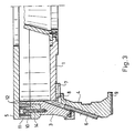
- the piston pressure acting on the upper plate 1 pushes out the sliding segments and keeps them open in the radial direction (FIG. 3).
- the inserted green tire collides with the downwardly moving segments (with the shaped segments 16 screwed into the sliding segments 4).
- the size of the opening of the upper molded part is determined by the position of the limiters 13 arranged on the locking ring 3.
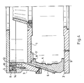
- the sliding segments 4 reach the base plate 2 (FIG. 4), and the locking ring 3 moving downward carries out the closing process.
- the downward movement of the locking ring 3 forces the sliding segments 4, which are in contact on the conical surface or on the mantle of the pyramid, to move radially.
- the piston rod of the working cylinder is continuously pushed back as the top plate 1 approaches the fixed plate of the dome.
- the built-in mold halves 17 and the mold segments 16 screwed onto the sliding segments 4 adapt to one another, thereby creating the self-contained vulcanizing mold cavity.
- the upper plate 1 nestles against the upper plate of the dome (FIG. 1).
- the prestressing gaps are reduced by the pressure effect until they gradually disappear completely, as a result of which the two metal levels touch each other.
- the vulcanization itself takes place in a traditional way.
- the closed mold is held in a compressed state with a force corresponding to the vulcanizing pressure of the vulcanizing machine. Due to the increased pressure effect, the bellows bag presses the green tire into the pattern, as a result of which the tire subjected to pressure takes on the shape of the mold cavity and the pattern is designed.
- the working cylinder holds the upper plate 1 in position. Then the lifting ring 3 pulls the sliding segments 4 pressed down with the upper plate gradually with the help of the built-in guide bar 6 to the outside. The opening in the radial direction is continued until the upper plate 1 reaches the limiter 13 (FIG. 4).
- the entire upper part is lifted up from the base plate 2 (FIG. 2), first the bridge of the vulcanizing machine is lifted vertically. At the end of the opening, the bridge of the machine with the dome mounted on it tilts so that a new green tire can be inserted easily. Prior to tilting the bridge, the opened sliding segments 4 must be operated with the help of the working cylinder and with the aid of the guide 7 mounted on the upper plate 1 with a "T" cross section and the upper sliding plates 8 are retracted (Fig. 5).
Landscapes
- Engineering & Computer Science (AREA)
- Mechanical Engineering (AREA)
- Moulds For Moulding Plastics Or The Like (AREA)
- Heating, Cooling, Or Curing Plastics Or The Like In General (AREA)
Abstract
Description
- Die Erfindung betrifft eine Vulkanisierform für eine Reifenvulkanisiermaschine, die gegenüber den bisher für ähnliche Zwecke verwendete Maschinen vielseitiger eingesetzt werden kann, da auf einfache Weise die vulkanisierenden Preßwerkzeuge für Gummireifen voneinander verschiedener Abmessungen ohne Schwierigkeiten, angepaßt werden können.
- Die bekannten Vulkanisierformen mit austauschbaren Musterungen, die sogenannten "Kontainer" sind von ihrer Art her einem einzigen Typ der Vulkanisiermaschinen, bzw. einem engen Bereich der Reifenabmessungen zugeordnet.
- Die sich aus der Produktion ergebenden Ungenauigkeiten, bzw. bei der Vulkanisierung entstehenden Deformationen können ausschließlich durch ein Auseinandernehmen des Kontainers eliminiert werden, wobei die von der Vulkanisierungstechnologie beanspruchten Vorspannungsspalte - auf deren Rolle später detailliert eingegangen wird - nur durch eine nachträgliche Bearbeitung der einzelnen Bestandteile des Kontainers auf den gewünschten Wert eingestellt werden können.
- Bei den Schließverfahren der Formsegmente, der radialen Einspannung des zu vulkanisierten Reifens, wird bereits seit langem die radiale Bewegung durch Gleiten entlang der Innenfläche des Kegelmantels angewendet. Eine derartige Lösung ist z. B. in dem deutschen Patent DE-PS 22 54 334 oder in der Patentschrift EP 0 170 109 beschrieben.
- Wenn die Vulkanisierform geschlossen wird, wirkt eine nach unten gerichtete Kraft auf das obenliegende strukturelle Element ein; diese Kraft muß auf die die radiale Einspannung des Rohreifens ausführenden Segmente übertragen werden und zwar derart, daß die Anordnung und die Einspannung möglichst am besten sind. Aus diesem Grund sieht man sogenannte Vorspannungsspalte vor, damit die zunehmende Druckkraft bis zu einer gewissen Grenze nur in Richtung der gleitenden Segmente angreift und erst nach dem Überschreiten des Grenzwertes auch die mittlere größere Fläche der oberen Platte aufliegt, wenn bereits die sich orientierende Bewegung gegenüber dem hohen Widerstand zum Stillstand gekommen ist. Das bedeutet, daß die Vorspannungsspalte zwischen jenen Teilen vorgesehen sind, die innerhalb der Flansche zweier, mit den oberen Flachebenen einander angepaßten strukturellen Elemente liegen, wobei die Größe und die sich aus dem Grundstoff und Abmessung der obersten gedrückten Platte ergebende elastische Deformation jenen kritischen Druckkraftwert bestimmen, bei dem die Spalte geschlossen sind. Falls die Vorspannungsspalte zu klein sind, kann es aufgrund des frühzeitigen Schließens sehr leicht vorkommen, daß durch den unbefriedigenden Stoß auf dem Reifen ein Grat entsteht. Wenn jedoch die Spalte zu groß sind, kann die obere Formhälfte durch die Hebewirkung des vulkanisierenden Pressens hochgehoben werden, wodurch der vulkanisierte Reifen halbseitig wird.
- Der Nachteil der gegenwärtig bekannten und zur Verwendung kommenden Einrichtungen besteht darin, daß die Vorspannungsspalte nur mit Schwierigkeiten, ausschließlich durch Spanabhebung modifiziert werden können. Den Reifen mit voneinander verschiedenen Abmessungen müssen Spalte mit voneinander verschiedenen Größen zugeordnet werden.
- Der Erfindung liegt die Aufgabe zugrunde, bei der Fertigung von voneinander verschiedenen Reifengrößen eine erhöhte technologische Elastizität und eine einfache reversible Veränderbarkeit der Vorspannungsspalte zu erreichen. Eine weitere Aufgabe besteht darin, die gegenwärtig üblichen Formsegmente und Preßmaschinen ohne Änderung weiterverwenden zu können.
- Dabei gelangte man zu der Erkenntnis, daß der Mechanismus des Formverschlusses das Einsetzen von Formsegmenten verschiedener Größen in die Vulkanisierform dadurch ermöglicht, daß die auftretenden Kraftverhältnisse beim Schließen den optimalen Verhältnissen der Vulkanisierung entsprechen. Desweiteren besteht die Möglichkeit im Interesse der Qualitätsverbesserung ein reversibles Stellwerk zu konstruieren, daß die Vorspannungsspalte regelt.
- Um das gesetzte Ziel erreichen zu können, wurde eine Vulkanisierform entwickelt, die in den Vulkanisieranlagen für Kraftfahrzeugreifen, insbesondere für Radialreifen eingesetzt werden kann. Die Verbindung mit dem Dom der Vulkanisiermaschine wird mit einem Auffangring hergestellt, dem sich die weiteren Elemente des oberen, sich in vertikaler Richtung bewegenden Teils - eine obere Platte, ein Verschlußring, die gleitenden Segmente, die der inneren kegel- oder pyramidenförmigen Fläche des Verschlußringes mit Führungsschienen schräg bewegbar angeschlossen sind, an denen die Formsegmene austauschbar befestigt sind - anpassen. Die Bewegung der Gleitsegmente in horizontaler Richtung wird mit Gleitplatten gefördert. Die Größe der Spalte zwischen dem Auffangring und der oberen Platte kann mit Hilfe eines als Korrekturring dienenden Ausgleichsring eingestellt werden, der mit einer Stell- und Befestigungsschraube versehen ist.
- Die Erfindung wird anhand einer vorteilhaften Ausführungsform, unter Bezugnahme auf die beiliegende Zeichnung näher erläutert. In der Zeichnung zeigt:
- Figur 1 einen radialen Halbschnitt einer geschlossenen Vulkanisierform,
- Figur 2 eine Draufsicht auf die Vulkanisierform nach Figur 1,
- Figuren 3 bis 7 voneinander verschiedene Radialschnitte der Vulkanisierform.
- Aus Figur 1 sind im radialen Schnitt die wichtigsten Elemente der im geschlossenen Zustand wiedergegebenen Vulkanisierform ersichtlich. Eine radiale Bewegung der auf einer Grundplatte 2 und einer oberen Platte 1 montierten, zwischen Leitplatten 8, 9 eingefügten Gleitsegmente kann durch die Gestaltung einer kegel- oder pyramidenförmigen Fläche hervorgerufen werden. Bei der Bewegung auf der konischen Fläche kann durch die Einstellung der eine Korrektur ermöglichenden Konstruktion und durch einen Austasch der Gleitplatten ein größerer Spärizitätsbereich umfaßt werden. Wie aus der Zeichnung ersichtlich, ist eine Führung 7 an der oberen Platte 1 montiert, in der ein Gleitsegment 4 unter Zwischenschaltung einer oberen Gleitplatte 8 gleitet. Wenn nun die Gleitbahn des Gleitsegments 4, die durch die Führung 7 und die obere Gleitplatte 8 gebildet ist, ausgetauscht wird, kann der Abstand zu der oberen Platte 1 geändert werden. Das gleiche ist bei der unteren Gleitplatte 9 und der Grundplatte 2 vorgesehen.
- Bei einer pyramidenförmigen Gleitfläche ist durch die eine Korrektur ermöglichende Konstruktion eine weitgehende Variation der Durchmesser der einsetzbaren Formen (Formsegmente 16 und Formhälften 17) möglich, ohne daß die Abmessungen und das Gewicht der Tragkonstruktion auf unwirtschaftliche Weise zunehmen würden. Gleichzeitig verursachen im Gegensatz zu der konischen Lösung die große Verschiebung des Verschlußringes 3 und der Gleitsegmente 4 keine geometrischen Ungenauigkeiten.
- Unter der eine Korrektur ermöglichenden Konstruktion wird ein Ausgleichsring 11 mit den sich darin befindenden Stellelementen, vorteilhafterweise mit Stellschrauben 10 und Befestigungsschrauben 14 sowie mit ausbaubaren Einsatzringen 12 verstanden.
- Infolge ihrer Positionierung übertragen die im Ausgleichsring 11 eingebauten Stellschrauben 10 die Schließkraft der Vulkanisiermaschine unmittelbar auf die Segmente, wodurch die Gefahr einer Deformation auf ein Minimum herabgesetzt wird.
- Die in dem Formträger eingebauten Gleitsegmente 4 wurden so bemessen, daß die bei der Vulkanisierung auftretende Schließkraft die Gleitflächen in Abhängigkeit deren Grundstoffs belastet, so z. B. werden hier Gleitelemente aus selbstschmierenden Grundstoffen verwendet, bei denen Schmiermittl nicht beansprucht werden. Der Vorteil ohne Schmiermittel auskommen zu können, zeigt sich einerseits in einer vereinfachten Wartung und andererseits wird auf keinen Fall das ausstülpende Schmiermittel in das Rohgummi eingepreßt, wodurch Ausschuß vermieden werden kann. Im geschlossenen Zustand berühren die Gleitsegmente 4 einander nicht. Die eingebauten Formsegmente 16 und die daran anschließenden Formhälften 17 begrenzen den geschlossenen Formhohlraum.
- Durch die Modifizierung der entsprechenden strukturellen Elemente des Formträgers kann eine innere Heizung geschaffen werden. Einen Freiheitsgrad des Formträgers erfordert die Zusammenführung des unteren stationären und des oberen sich bewegenden Teils nicht, so daß die Zusammenführung nur bei dem Einbau in die Vulkanisiermaschine eine Rolle spielt.
- Die zwei wichtigsten Teile des Formträgers sind der sich bewegende Teil und der stationäre Teil.
- Der sich bewegende Teil, der in den Dom der Vulkanisiermaschine eingebaut wird, setzt sich aus den folgenden Komponenten zusammen:
- Der obere sich bewegende Teil der Form wird mittels des Auffangrings 5 an den Befestigungsbohrungen des Doms befestigt.
- Der Formträger ist über die obere Platte 1 an den Arbeitszylinder angeschlossen. Die sich den Gleitsegmenten 4 anschließenden muldenförmig ausgestalteten Führungen 7 mit einem "T"-Querschnitt sind unter Zwischenschaltung der austauschbaren oberen Gleitplatten 8 an der oberen Platte 1 montiert. Die obere Formhälfte 17 ist mit der oberen Platte 1 verschraubt.
- Die innere kegelförmige Fläche des Verschlußringes 3 - vorteilhaft mit einem Halböffnungswinkel von 23 ° - sperrt die Gleitsegmente 4 ab. Auf der Innenfläche ist die den Auszug des Gleitsegments gewährleistende mit Bronze ausgekleidete Bahn der prismatischen Führungsleiste 6 angeordnet. Die in die Außenfläche des Verschlußringes 3 hineingefräste Bahn erstreckt sich bis zu dem auf der Grundplatte gebauten Zuführer 15.
- Das Gleitsegment 4 ist mit der konischen Fläche dem Verschlußring 3 zugewandt und kann mit Hilfe der darauf montierten prismatischen Führungsleiste 6 herausgezogen werden. Um die Reibung herabzusetzen sind vorteilhafterweise die selbstschmierenden Gleitplatten 8, 9 vorgesehen. Die Formsegmenten 16 sind mit Schrauben an den Gleitsegmenten befestigt.
- Mit Hilfe der in dem Ausgleichsring 11 eingebauten Stellschraube 10 können die Vorspannungsspalte modifiziert bzw. der einbaubare Durchmesser verringert werden. Durch den Ausbau der Einsatzringe 12 kann wiederum der einbaubare Durchmesser vergrößert werden (Fig. 6).
- Durch den Austausch der unteren Gleitplatte 9 bzw. der oberen Gleitplatte 8 kann die Sphärizitätsdimension der in den Formträger einbaubaren Formen geändert werden (Fig. 7).
- Der Aufbau des auf dem Tisch der Vulkanisiermaschine befestigten Unterteils ist, wie folgt.
- Die zentrierende Bohrung der Grundplatte 2 bestimmt die Position der Vulkanisierform in der Vulkanisiermaschine. Der Unterteil wird mit Hilfe der in der Grundplatte 2 vorgesehenen Bohrungen an dem Tisch der Vulkanisiermaschine befestigt, so daß die untere Formhälfte 17 an dem Tisch befestigt ist.
- Der Zuführer 15, der an der Grundplatte 2 befestigt ist, bestimmt die Lage des Oberteils und des Unterteils.
- Als austauschbare Bestandteile werden in den Formträger für den jeweils herzustellenden Reifen folgende spezifische Formkomponenten eingebaut.
- untere-obere Formhälfte 17,
- Formsegmente 16,
- Form- und Balgringe. - Zuerst wird die Funktion der erfindungsgemäßen Vulkanisierform während des Schließvorgangs beschrieben. In der ersten Phase der Schließbewegung drückt der auf die obere Platte 1 einwirkende Kolbendruck die Gleitsegmente heraus und hält diese in radialer Richtung geöffnet (Fig. 3). Durch diesen geöffneten Zustand kann erreicht werden, daß der eingelegte Rohreifen mit den sich abwärts bewegenden Segmenten (mit den in den Gleitsegmenten 4 eingeschraubten Formsegmenten 16) zusammenstößt. Die Größe der Öffnung des oberen Formteils wird durch die Position der an dem Verschlußring 3 angeordneten Begrenzer 13 bestimmt.
- In der zweiten Phase des Schließprozesses erreichen die Gleitsegemente 4 die Grundplatte 2 (Fig. 4), und der sich abwärts bewegende Verschlußring 3 führt dabei den Schließvorgang durch. Die nach unten gerichtete Bewegung des Verschlußringes 3 zwingt die auf der Kegelfläche bzw. auf dem Mantel der Pyramide in Berührung stehenden Gleitsegmente 4 zu einer radialen Verschiebung. In dieser Phase des Schließens wird die Kolbenstange des Arbeitszylinders kontinuierlich zurückgedrückt, während sich die obere Platte 1 der befestigten Platte des Doms nähert. Nach erfolgter Beendigung des Schließprozesses passen sich die eingebauten Formhälften 17 und die auf den Gleitsegmenten 4 aufgeschraubten Formsegmenten 16 einander an, wodurch der in sich geschlossene vulkanisierende Formhohlraum entsteht. Die obere Platte 1 schmiegt sich mit der ausgebauten Formhälfte 17 an die obere Platte des Doms (Fig. 1) an. Durch die Druckwirkung verringern sich die Vorspannungsspalte, bis sie allmählich vollkommen verschwinden, wodurch die beiden Metallebenen einander berühren.
- Die Vulkanisierung selbst findet auf traditionelle Weise statt.
- Die geschlossene Form wird mit einer dem Vulkanisierdruck der Vulkanisiermaschine entsprechenden Kraft in einem zusammengepreßten Zustand gehalten. Durch die erhöhte Druckwirkung preßt der Balgsack den Rohreifen in die Musterung ein, wodurch der dem Druck ausgesetzte Reifen die Form des Formhohlraumes annimmt und die Musterung ausgestaltet wird.
- In der ersten Phase des Öffnens, wobei die schließende Kraft der Vulkanisiermaschine allmählich aufhört, hält der Arbeitszylinder die obere Platte 1 in ihrer Stellung. Danach zieht der sich hochhebende Verschlußring 3 die mit der oberen Platte herabgepreßten Gleitsegmente 4 mit Hilfe der eingebauten Führungsleiste 6 allmählich nach außen. Das Öffnen in radialer Richtung wird solange fortgesetzt, bis die obere Platte 1 die Begrenzer 13 erreicht (Fig. 4).
- Zuletzt wird der gesamte Oberteil von der Grundplatte 2 hochgehoben (Figur 2), zuerst wird die Brücke der Vulkanisiermaschine vertikal angehoben. Am Ende des Öffnens kippt die Brücke der Maschine mit dem darauf montierten Dom zusammen, damit ein neuer Rohreifen leicht eingesetzt werden kann. Dem Kippen der Brücke vorangehend müssen die geöffneten Gleitsegmente 4 mit Hilfe des Arbeitszylinders und unter Zuhilfenahme der auf der oberen Platte 1 montierten Führung 7 mit einem "T"-Querschnitt und der oberen Gleitplatten 8 zurückgezogen werden (Fig. 5).
Claims (6)
Applications Claiming Priority (2)
| Application Number | Priority Date | Filing Date | Title |
|---|---|---|---|
| HU875722A HUT49071A (en) | 1987-12-16 | 1987-12-16 | Mould carrying and actuating device for vulcanizing radial tyres |
| HU572287 | 1987-12-16 |
Publications (2)
| Publication Number | Publication Date |
|---|---|
| EP0320588A2 true EP0320588A2 (de) | 1989-06-21 |
| EP0320588A3 EP0320588A3 (de) | 1990-01-31 |
Family
ID=10970635
Family Applications (1)
| Application Number | Title | Priority Date | Filing Date |
|---|---|---|---|
| EP88116700A Withdrawn EP0320588A3 (de) | 1987-12-16 | 1988-10-07 | Vulkanisierform für eine Reifenvulkanisiermaschine |
Country Status (4)
| Country | Link |
|---|---|
| US (1) | US4931004A (de) |
| EP (1) | EP0320588A3 (de) |
| CN (1) | CN1014220B (de) |
| HU (1) | HUT49071A (de) |
Cited By (5)
| Publication number | Priority date | Publication date | Assignee | Title |
|---|---|---|---|---|
| EP0569909A1 (de) * | 1992-05-13 | 1993-11-18 | Sedepro | Reifenform und Verfahren zum Formen eines Reifens |
| FR2691095A1 (fr) * | 1992-05-13 | 1993-11-19 | Sedepro | Moule pour pneumatique, et procédé de moulage du pneumatique. |
| FR2699853A1 (fr) * | 1992-12-24 | 1994-07-01 | Sedepro | Moule pour pneumatique, et procédé de moulage du pneumatique. |
| FR2739055A1 (fr) * | 1995-09-26 | 1997-03-28 | Michelin & Cie | Moule pour pneumatique a pression interne controlee |
| WO2014044713A1 (fr) * | 2012-09-24 | 2014-03-27 | Compagnie Generale Des Etablissements Michelin | Dispositif de vulcanisation à secteurs mobiles radialement pour pneumatique |
Families Citing this family (7)
| Publication number | Priority date | Publication date | Assignee | Title |
|---|---|---|---|---|
| FR2661129B1 (fr) * | 1990-04-19 | 1992-07-10 | Kleber Pneumatiques | Moules a secteurs a recul radial combine a un basculement. |
| RU2115553C1 (ru) * | 1997-04-18 | 1998-07-20 | Закрытое акционерное общество Проектно-производственное объединение "Старт" | Секторная пресс-форма двухфазного действия для вулканизации покрышек пневматических шин |
| US6315070B1 (en) | 1999-02-11 | 2001-11-13 | Carroll Tech, Inc. | Snowmobile track repair system, apparatus and method |
| DE19950621A1 (de) * | 1999-10-20 | 2001-04-26 | Schuler Kunststofftechnik Gmbh | Gleitlager |
| FR3024074B1 (fr) | 2014-07-25 | 2016-09-02 | Michelin & Cie | Moule de vulcanisation pour pneumatique a fermeture optimisee |
| JP6593514B1 (ja) * | 2018-10-11 | 2019-10-23 | 横浜ゴム株式会社 | タイヤ加硫装置および方法 |
| CN117261311B (zh) * | 2023-11-17 | 2024-02-13 | 山东豪迈机械科技股份有限公司 | 预加载实时调整装置及其控制方法 |
Family Cites Families (12)
| Publication number | Priority date | Publication date | Assignee | Title |
|---|---|---|---|---|
| GB975644A (en) * | 1963-07-24 | 1964-11-18 | Mcneil Machine & Eng Co | Improvements in tyre presses |
| US3461502A (en) * | 1965-10-18 | 1969-08-19 | Amk Subsidiary Corp | Tire curing press |
| US3464090A (en) * | 1967-09-26 | 1969-09-02 | Nrm Corp | Tire curing press |
| DE2139011C3 (de) * | 1971-08-04 | 1975-02-06 | Continental Gummi-Werke Ag, 3000 Hannover | Preßform, insbesondere Vulkanisierform, für Fahrzeugluftreifen |
| US3910735A (en) * | 1971-10-15 | 1975-10-07 | Pirelli | Apparatus for molding and curing a pneumatic tire in a perfectly centered position with respect to the equatorial plane of the curing mold |
| US3797979A (en) * | 1972-03-14 | 1974-03-19 | Goodyear Tire & Rubber | Segmented tire mold apparatus |
| US3778203A (en) * | 1972-04-11 | 1973-12-11 | K Macmillan | Matrix assembly with segmented matrices |
| US3787155A (en) * | 1972-08-01 | 1974-01-22 | K Zangl | Segmented vulcanising tire mould |
| CA977112A (en) * | 1972-09-15 | 1975-11-04 | Irco Industries Inc. | Segmental tire curing mould |
| DE2254334C3 (de) * | 1972-11-07 | 1978-08-24 | Marangoni Meccanica S.P.A., Rovereto (Italien) | Vulkanisierform für Luftreifen |
| IT1176523B (it) * | 1984-08-01 | 1987-08-18 | Pirelli | Perfezionamenti nelle presse per la vulcanizzazione |
| JPS6248515A (ja) * | 1985-08-28 | 1987-03-03 | Bridgestone Corp | 分割型加硫モ−ルド |
-
1987
- 1987-12-16 HU HU875722A patent/HUT49071A/hu unknown
-
1988
- 1988-10-07 EP EP88116700A patent/EP0320588A3/de not_active Withdrawn
- 1988-10-11 US US07/255,769 patent/US4931004A/en not_active Expired - Fee Related
- 1988-10-18 CN CN88108453.0A patent/CN1014220B/zh not_active Expired
Cited By (11)
| Publication number | Priority date | Publication date | Assignee | Title |
|---|---|---|---|---|
| EP0569909A1 (de) * | 1992-05-13 | 1993-11-18 | Sedepro | Reifenform und Verfahren zum Formen eines Reifens |
| FR2691095A1 (fr) * | 1992-05-13 | 1993-11-19 | Sedepro | Moule pour pneumatique, et procédé de moulage du pneumatique. |
| FR2699853A1 (fr) * | 1992-12-24 | 1994-07-01 | Sedepro | Moule pour pneumatique, et procédé de moulage du pneumatique. |
| FR2739055A1 (fr) * | 1995-09-26 | 1997-03-28 | Michelin & Cie | Moule pour pneumatique a pression interne controlee |
| EP0767050A1 (de) * | 1995-09-26 | 1997-04-09 | COMPAGNIE GENERALE DES ETABLISSEMENTS MICHELIN-MICHELIN & CIE | Reifenform mit kontrollierbarem Innendruck |
| US5814263A (en) * | 1995-09-26 | 1998-09-29 | Compagnie Generale Des Etablissements Michelin-Michelin & Cie | Tire mold with controlled internal pressure |
| WO2014044713A1 (fr) * | 2012-09-24 | 2014-03-27 | Compagnie Generale Des Etablissements Michelin | Dispositif de vulcanisation à secteurs mobiles radialement pour pneumatique |
| FR2995817A1 (fr) * | 2012-09-24 | 2014-03-28 | Michelin & Cie | Dispositif de vulcanisation a secteurs mobiles radialement pour pneumatique |
| CN104684717A (zh) * | 2012-09-24 | 2015-06-03 | 米其林集团总公司 | 用于轮胎的具有可径向移动部段的硫化设备 |
| US9259863B2 (en) | 2012-09-24 | 2016-02-16 | Compagnie Generale Des Etablissements Michelin | Vulcanizing device with radially mobile segments for a tire |
| CN104684717B (zh) * | 2012-09-24 | 2016-11-23 | 米其林集团总公司 | 用于轮胎的具有可径向移动部段的硫化设备 |
Also Published As
| Publication number | Publication date |
|---|---|
| CN1033592A (zh) | 1989-07-05 |
| EP0320588A3 (de) | 1990-01-31 |
| CN1014220B (zh) | 1991-10-09 |
| HUT49071A (en) | 1989-08-28 |
| US4931004A (en) | 1990-06-05 |
Similar Documents
| Publication | Publication Date | Title |
|---|---|---|
| DE2708011C2 (de) | Mehrteilige Form zum Herstellen von Reifendecken | |
| DE69101577T2 (de) | Form mit schwenkbaren und radial bewegbaren Segmenten. | |
| EP0722820B1 (de) | Holmlose Formschliesseinrichtung | |
| EP0418779A1 (de) | Verfahren zum Herstellen von Werkstücken durch Schneiden, insbesondere in einem Konterschneidwerkzeug | |
| EP0320588A2 (de) | Vulkanisierform für eine Reifenvulkanisiermaschine | |
| EP4076881B1 (de) | Vorrichtung zur herstellung von betonsteinen | |
| DE3752181T2 (de) | Rotations-Spritzblasformmaschine | |
| DE3346466A1 (de) | Vorrichtung zum gleichzeitigen oeffnen und schliessen von mehreren parison-formen in einem begrenzten raum | |
| DE3325693C2 (de) | Vorrichtung zum Be- und Entladen einer Vulkanisierpresse für Kraftfahrzeugreifen | |
| DE3821548C2 (de) | ||
| EP0260628B1 (de) | Reifenvulkanisierform | |
| DE1778616A1 (de) | Reifenvulkanisierpresse mit Heizbelag | |
| DE60302471T2 (de) | Ausrichtungsmittel für eine spritzgiessvorrichtung | |
| DE2751036A1 (de) | Presse fuer reifenvulkanisierformen | |
| CH617161A5 (de) | ||
| DE2218562A1 (de) | Vulkanisierform fuer luftreifen von fahrzeugen | |
| DE2112651B2 (de) | Spann- und Lösevorrichtung fur Werkzeuge an Bohr-, Fräs- u.dgl. Werkzeugmaschinen | |
| DE1151370B (de) | Vorrichtung zum Entfernen von vulkanisierten Reifen aus einer Presse zum Formen und Vulkanisieren von Reifen | |
| DE1652614A1 (de) | Presse mit einem aus dieser herausfuehrbaren Verschiebetisch od.dgl. | |
| DE69117232T2 (de) | System zum Formen eines Kunststoffgriffs für einen Behälterdeckel und Behälterdeckel | |
| DE3686744T2 (de) | Spritzstreckblasformmaschine. | |
| DE69511510T2 (de) | Plattenspritzgiessvorrichtung mit Führungsmitteln für die Formöffnung | |
| DE69516740T2 (de) | Reifenvulkanisierpresse | |
| DE3800234A1 (de) | Reifenvulkanisiermaschine | |
| EP0161643B1 (de) | Einrichtung zum Auswerfen der Formteile aus der Matrize in einer Umformpresse |
Legal Events
| Date | Code | Title | Description |
|---|---|---|---|
| PUAI | Public reference made under article 153(3) epc to a published international application that has entered the european phase |
Free format text: ORIGINAL CODE: 0009012 |
|
| AK | Designated contracting states |
Kind code of ref document: A2 Designated state(s): AT DE ES FR GB IT SE |
|
| PUAL | Search report despatched |
Free format text: ORIGINAL CODE: 0009013 |
|
| AK | Designated contracting states |
Kind code of ref document: A3 Designated state(s): AT DE ES FR GB IT SE |
|
| 17P | Request for examination filed |
Effective date: 19900730 |
|
| 17Q | First examination report despatched |
Effective date: 19910814 |
|
| RAP1 | Party data changed (applicant data changed or rights of an application transferred) |
Owner name: TAUFORM KFT. |
|
| STAA | Information on the status of an ep patent application or granted ep patent |
Free format text: STATUS: THE APPLICATION IS DEEMED TO BE WITHDRAWN |
|
| 18D | Application deemed to be withdrawn |
Effective date: 19930501 |