EP0321430B1 - Méthode de fabrication pour un comprimé tubulaire et un appareil pour sa mise en oeuvre - Google Patents
Méthode de fabrication pour un comprimé tubulaire et un appareil pour sa mise en oeuvre Download PDFInfo
- Publication number
- EP0321430B1 EP0321430B1 EP88850424A EP88850424A EP0321430B1 EP 0321430 B1 EP0321430 B1 EP 0321430B1 EP 88850424 A EP88850424 A EP 88850424A EP 88850424 A EP88850424 A EP 88850424A EP 0321430 B1 EP0321430 B1 EP 0321430B1
- Authority
- EP
- European Patent Office
- Prior art keywords
- compact
- abutment surface
- circumferential surface
- lining
- support means
- Prior art date
- Legal status (The legal status is an assumption and is not a legal conclusion. Google has not performed a legal analysis and makes no representation as to the accuracy of the status listed.)
- Expired - Lifetime
Links
- 238000000034 method Methods 0.000 title claims description 29
- 238000004519 manufacturing process Methods 0.000 title claims description 9
- 239000000843 powder Substances 0.000 claims description 13
- 239000000463 material Substances 0.000 claims description 8
- 230000014759 maintenance of location Effects 0.000 claims description 6
- 238000005245 sintering Methods 0.000 claims description 6
- 238000007789 sealing Methods 0.000 claims description 5
- 230000000717 retained effect Effects 0.000 claims description 4
- 238000010438 heat treatment Methods 0.000 claims description 3
- 238000000227 grinding Methods 0.000 claims description 2
- 239000011148 porous material Substances 0.000 claims description 2
- 238000005520 cutting process Methods 0.000 description 6
- 238000000465 moulding Methods 0.000 description 6
- 239000002184 metal Substances 0.000 description 4
- 229910052751 metal Inorganic materials 0.000 description 4
- 238000005056 compaction Methods 0.000 description 3
- 229910010293 ceramic material Inorganic materials 0.000 description 2
- 238000009694 cold isostatic pressing Methods 0.000 description 2
- 229920001971 elastomer Polymers 0.000 description 2
- 239000000806 elastomer Substances 0.000 description 2
- 238000007493 shaping process Methods 0.000 description 2
- OKTJSMMVPCPJKN-UHFFFAOYSA-N Carbon Chemical compound [C] OKTJSMMVPCPJKN-UHFFFAOYSA-N 0.000 description 1
- XEEYBQQBJWHFJM-UHFFFAOYSA-N Iron Chemical compound [Fe] XEEYBQQBJWHFJM-UHFFFAOYSA-N 0.000 description 1
- 238000000137 annealing Methods 0.000 description 1
- 238000010420 art technique Methods 0.000 description 1
- 239000000919 ceramic Substances 0.000 description 1
- 238000002485 combustion reaction Methods 0.000 description 1
- 238000005553 drilling Methods 0.000 description 1
- 238000000462 isostatic pressing Methods 0.000 description 1
- 239000000203 mixture Substances 0.000 description 1
- 239000004482 other powder Substances 0.000 description 1
- 239000002245 particle Substances 0.000 description 1
- 230000002093 peripheral effect Effects 0.000 description 1
- 230000002035 prolonged effect Effects 0.000 description 1
- 238000004381 surface treatment Methods 0.000 description 1
Images
Classifications
-
- B—PERFORMING OPERATIONS; TRANSPORTING
- B23—MACHINE TOOLS; METAL-WORKING NOT OTHERWISE PROVIDED FOR
- B23B—TURNING; BORING
- B23B31/00—Chucks; Expansion mandrels; Adaptations thereof for remote control
- B23B31/02—Chucks
- B23B31/24—Chucks characterised by features relating primarily to remote control of the gripping means
- B23B31/30—Chucks characterised by features relating primarily to remote control of the gripping means using fluid-pressure means in the chuck
- B23B31/305—Chucks characterised by features relating primarily to remote control of the gripping means using fluid-pressure means in the chuck the gripping means is a deformable sleeve
-
- B—PERFORMING OPERATIONS; TRANSPORTING
- B22—CASTING; POWDER METALLURGY
- B22F—WORKING METALLIC POWDER; MANUFACTURE OF ARTICLES FROM METALLIC POWDER; MAKING METALLIC POWDER; APPARATUS OR DEVICES SPECIALLY ADAPTED FOR METALLIC POWDER
- B22F3/00—Manufacture of workpieces or articles from metallic powder characterised by the manner of compacting or sintering; Apparatus specially adapted therefor ; Presses and furnaces
- B22F3/02—Compacting only
-
- B—PERFORMING OPERATIONS; TRANSPORTING
- B22—CASTING; POWDER METALLURGY
- B22F—WORKING METALLIC POWDER; MANUFACTURE OF ARTICLES FROM METALLIC POWDER; MAKING METALLIC POWDER; APPARATUS OR DEVICES SPECIALLY ADAPTED FOR METALLIC POWDER
- B22F3/00—Manufacture of workpieces or articles from metallic powder characterised by the manner of compacting or sintering; Apparatus specially adapted therefor ; Presses and furnaces
- B22F3/02—Compacting only
- B22F3/04—Compacting only by applying fluid pressure, e.g. by cold isostatic pressing [CIP]
Definitions
- the present invention relates to a method for handling tubular compacts in connection with the manufacture thereof, and a device for carrying out the method.
- the invention has been developed especially for use in connection with cold isostatic pressing of metal powder to form thin-walled, hollow cylindrical compacts, such as cylinder linings for internal combustion engines. It should however be emphasised from the very outset that the invention is also applicable both to other powder materials, for instance ceramic materials, which are compactible to give the required inherent strength, and to compacts of non-cylindrical cross-section.
- an at least partially elastic moulding tool is first filled with metal powder and then closed and subjected to an isostatic pressure for compacting the powder into a so-called compact or "green body".
- the resulting compact has a relatively low strength and, to obtain the desired final strength, it must be subjected to one or more subsequent heat treatment steps, such as soft annealing, presintering or sintering.
- the thus obtained sintered compact which has a considerably higher strength than the solely compacted powder body, can then be handled and shaped without any risk of breaking or being damaged.
- such shaping typically comprises turning one or both circumferential surfaces of the lining, such that the circumferential wall of the lining can satisfy high demands on dimensional tolerances of the wall thickness.
- such after-treatment may however include other operations than turning, for instance grinding, drilling etc.
- An object of the present invention therefore is to offer a technique which overcomes the above-mentioned drawbacks, i.e. which largely prevents tool wear, allows reuse of material removed during processing, ensures an extended life of the moulding tool and thus larger dimensional tolerances in the compact, and which also overcomes the problem of skewness in slitted linings.
- this object is achieved by a technique which makes it possible to handle and process the compact directly after compacting and before any additional strength-increasing processing step, such as sintering or presintering.
- the method according to the invention is characterised by applying one circumferential surface of the compact at a minimum distance required for said application, from an abutment surface corresponding to said one circumferential surface, and thereafter evacuating the space between said one circumferential surface and said abutment surface, such that the compact, while undergoing a certain deformation to bridge said distance, is sucked against the abutment surface so as to be firmly retained against it.
- the other circumferential surface of the compact thus retained is preferably made accessible to processing, for instance turning.
- One essential feature of the inventive method resides in using the deformability of the compact in a state directly after compacting or in a state in which the strength of the compact has been increased but to a relatively small extent, e.g. by a certain degree of heating, in order to ensure retention of the compact against the abutment surface.
- the inventive method further yields the advantage of permitting larger dimensional tolerances for the "green body" since subsequent processing of the body to desired tolerances does not involve any of the above-mentioned problems inherent in the prior art technique.
- Another advantage of the inventive method is that processing can be carried out considerably faster than the processing of sintered bodies having high hardness.
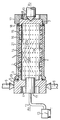
- the device shown in the drawing comprises a support means in the form of an elongate hollow supporting cylinder 1 the circumferential wall of which is provided with a large number of evenly distributed through openings 2.
- the cylinder 1 is connected to a first end wall 4 having a peripheral gripping surface 5 for engagement with turning centres 6.
- the cylinder 1 is closed by a second end wall 8 having a central conical recess 9 for receiving a supporting centre 10.
- the device further comprises a swivel pipe 11 centrally disposed in the first end wall 4 and connected by a connection 12 to a vacuum pump 13.
- an isostatically compacted cylindrical PM-lining 14 - a so-called “green body” - is applied on the cylinder 1 with a minimum distance required for this application between an outer cylindrical abutment surface 15 of the supporting cylinder 1 and the inner cylindrical circumferential surface 16 of the PM-lining 14.
- a sealing end wall 17 has been mounted on the other end 7 of the cylinder 1 to sealingly engage the corresponding end of the lining 14 by the intermediary of an O-ring 18.
- a similar O-ring 19 is provided at the opposite end of the lining in order, together with the O-ring 18, to seal the space between the lining 14 and the cylinder 1.
- the dash-dot lines schematically show oblique distributing grooves 20 which are provided in the outer abutment surface 15 of the cylinder 1 and extend between the openings 2.
- the grooves 20 serve to distribute the suction forces produced when using the invention.
- the sealing end wall 17 was mounted for sealing the space between the lining 14 and the cylinder 1.
- the vacuum pump 13 was thereafter started for evacuating said space via the connection 12, the swivel pipe 11, the interior of the cylinder 1 and the openings 2.
- the depression in the openings 2 was measured at about 0.95 bar.
- the lining 14, while undergoing a certain deformation to bridge said clearance of 0.05 mm, was sucked fast to the abutment surface 15 of the cylinder 1.
- the outer circumferential surface 21 of the lining 14 now retained was thereafter processed at a speed of the cylinder 1 and the lining 14 of 900 rpm and with a feed of 0.3 mm per revolution.
- the variation of the wall thickness was measured at about 0.05 mm, which satisfies the dimensional tolerances set.
- the lining 14 was released from the cylinder 1 and subjected to sintering to obtain the desired strength.
- the clearance between the inner circumferential surface 16 of the PM-lining 14 and the outer abutment surface 15 of the cylinder 1 should be 0.1 mm or less, preferably in the order of 0.05 mm. It further appears that the diameter of the openings 2 should be less than 5 mm, preferably less than 2 mm. Further, it has been established that the distributing grooves 20 formed in the abutment surface 15 and extending between the openings 2 positively assist in obtaining a more uniform retention of the lining 14 and also positively increase the friction between the lining 14 and the cylinder 1.
- the invention is not restricted to metal powder, isostatic pressing or hollow cylindrical compacts.
- the technique is also applicable e.g. to ceramic powders and compacts other than that shown in the Figure.
- the retention of the compact can also be performed at its outer circumferential surface if, for example, it is desirable to work its inner circumferential surface, in which case the support means may instead be designed as a sleeve in which the compact can be inserted with a slight clearance between the outer circumferential surface of the compact and the inner circumferential surface of the sleeve.
Landscapes
- Engineering & Computer Science (AREA)
- Mechanical Engineering (AREA)
- Manufacturing & Machinery (AREA)
- Physics & Mathematics (AREA)
- Fluid Mechanics (AREA)
- Powder Metallurgy (AREA)
- Press Drives And Press Lines (AREA)
- Manufacturing Of Tubular Articles Or Embedded Moulded Articles (AREA)
- Forging (AREA)
- Formation And Processing Of Food Products (AREA)
- General Preparation And Processing Of Foods (AREA)
Claims (9)
Applications Claiming Priority (2)
| Application Number | Priority Date | Filing Date | Title |
|---|---|---|---|
| SE8705053 | 1987-12-18 | ||
| SE8705053A SE460955B (sv) | 1987-12-18 | 1987-12-18 | Saett vid framstaellning av en roerformig pulverpresskropp samt en foer genomfoerande av saettet avsedd anordning |
Publications (2)
| Publication Number | Publication Date |
|---|---|
| EP0321430A1 EP0321430A1 (fr) | 1989-06-21 |
| EP0321430B1 true EP0321430B1 (fr) | 1992-07-29 |
Family
ID=20370640
Family Applications (1)
| Application Number | Title | Priority Date | Filing Date |
|---|---|---|---|
| EP88850424A Expired - Lifetime EP0321430B1 (fr) | 1987-12-18 | 1988-12-15 | Méthode de fabrication pour un comprimé tubulaire et un appareil pour sa mise en oeuvre |
Country Status (7)
| Country | Link |
|---|---|
| US (1) | US4880598A (fr) |
| EP (1) | EP0321430B1 (fr) |
| JP (1) | JPH01268801A (fr) |
| KR (1) | KR890009508A (fr) |
| DE (1) | DE3873293T2 (fr) |
| ES (1) | ES2034397T3 (fr) |
| SE (1) | SE460955B (fr) |
Families Citing this family (3)
| Publication number | Priority date | Publication date | Assignee | Title |
|---|---|---|---|---|
| AT391105B (de) * | 1988-10-07 | 1990-08-27 | Boehler Gmbh | Vormaterial fuer die erzeugung von verbundwerkstoffen |
| US5749331A (en) * | 1992-03-23 | 1998-05-12 | Tecsyn, Inc. | Powdered metal cylinder liners |
| WO2008036926A1 (fr) * | 2006-09-22 | 2008-03-27 | Gkn Sinter Metals, Llc | Fabrication de composant de métal en poudre à paroi mince |
Family Cites Families (12)
| Publication number | Priority date | Publication date | Assignee | Title |
|---|---|---|---|---|
| US32389A (en) * | 1861-05-21 | l stuart | ||
| DE1045766B (de) * | 1956-05-02 | 1958-12-04 | Albert Fezer | Saugspannplatte zum Festspannen duennwandiger Werkstuecke, insbesondere duenner Bleche |
| DE1627191C3 (de) * | 1967-09-23 | 1974-04-11 | Goetzewerke Friedrich Goetze Ag, 5673 Burscheid | Vorrichtung zum Innenspannen von Ringen |
| USRE32389E (en) | 1980-04-10 | 1987-04-07 | Cameron Iron Works, Inc. | Method of producing a lined structure |
| US4477955A (en) * | 1980-04-10 | 1984-10-23 | Cameron Iron Works, Inc. | Method of producing a lined structure |
| JPS5725245A (en) * | 1980-07-18 | 1982-02-10 | Harada Chuzosho:Kk | Method and device for core molding |
| JPS5890347A (ja) * | 1981-11-20 | 1983-05-30 | Sintokogio Ltd | 主型鋳型の造型方法 |
| SE451239B (sv) * | 1982-11-18 | 1987-09-21 | Cold Isostatic Press Syst Kb | Kassett innefattande en pressform for semi-isostatisk kompaktering av ett pulver som er innehallet i pressformens kavitet |
| FR2537655A1 (fr) * | 1982-12-09 | 1984-06-15 | Cegedur | Chemises de moteurs a base d'alliages d'aluminium et de composes intermetalliques et leurs procedes d'obtention |
| US4544523A (en) * | 1983-10-17 | 1985-10-01 | Crucible Materials Corporation | Cladding method for producing a lined alloy article |
| JPS60103651U (ja) * | 1983-12-19 | 1985-07-15 | シチズン時計株式会社 | 真空吸着台 |
| DE3507179C1 (de) * | 1985-03-01 | 1985-10-31 | Eugen Dipl.-Ing. 8877 Burtenbach Bühler | Verfahren und Vorrichtung zur Herstellung von kastenlosen Giessformen |
-
1987
- 1987-12-18 SE SE8705053A patent/SE460955B/sv not_active IP Right Cessation
-
1988
- 1988-12-15 EP EP88850424A patent/EP0321430B1/fr not_active Expired - Lifetime
- 1988-12-15 DE DE8888850424T patent/DE3873293T2/de not_active Expired - Fee Related
- 1988-12-15 ES ES198888850424T patent/ES2034397T3/es not_active Expired - Lifetime
- 1988-12-15 US US07/284,562 patent/US4880598A/en not_active Expired - Lifetime
- 1988-12-19 KR KR1019880016933A patent/KR890009508A/ko not_active Withdrawn
- 1988-12-19 JP JP63320344A patent/JPH01268801A/ja active Pending
Non-Patent Citations (1)
| Title |
|---|
| Fertigungstechnik und Arbeitsmaschinen, page 699 (1972), Rowohlt Verlag * |
Also Published As
| Publication number | Publication date |
|---|---|
| JPH01268801A (ja) | 1989-10-26 |
| US4880598A (en) | 1989-11-14 |
| SE8705053D0 (sv) | 1987-12-18 |
| EP0321430A1 (fr) | 1989-06-21 |
| KR890009508A (ko) | 1989-08-02 |
| SE460955B (sv) | 1989-12-11 |
| SE8705053L (sv) | 1989-06-19 |
| DE3873293D1 (de) | 1992-09-03 |
| DE3873293T2 (de) | 1993-02-18 |
| ES2034397T3 (es) | 1993-04-01 |
Similar Documents
| Publication | Publication Date | Title |
|---|---|---|
| US4881431A (en) | Method of making a sintered body having an internal channel | |
| CA2191662C (fr) | Trepan a cone a denture fraisee en metal en poudre moulee sous pression | |
| EP0211643B1 (fr) | Consolidation d'ébauches multiples par métallurgie des poudres | |
| EP0053618B1 (fr) | Procede de fabrication de pieces metalliques comprimees et frittees | |
| US4137106A (en) | Super hard metal roll assembly and production thereof | |
| US5184769A (en) | Tooling and method for consolidating a filamentary reinforced metal matrix composite | |
| EP0949427A1 (fr) | Palier de butée dynamique en matériau poreux | |
| US4880598A (en) | Method for manufacturing a tubular compact | |
| JP2002502701A (ja) | 成形工具 | |
| FI80222C (fi) | Foerfarande foer framstaellning av en nit foer en fast dubb respektiva holkdubb och anlaeggning foer tillaempning av foerfarandet. | |
| EP0270549B1 (fr) | Procede de fabrication d'un dispositif de chemisage de cylindre | |
| JP2005326002A (ja) | 繊維ウエブをニードルパンチする方法 | |
| US6723277B1 (en) | Method for producing a milling disc and milling disc produced according to the inventive method | |
| JP3127587B2 (ja) | 分割金型の製造方法 | |
| KR102661946B1 (ko) | 실리콘카바이드 베어링 샤프트 또는 베어링의 제조방법, 원기둥 타입 실리콘카바이드 베어링 샤프트, 및 원형 튜브 타입 실리콘카바이드 베어링 | |
| JPH08169767A (ja) | セラミック素材及びこれを利用したセラミック製品の製造方法 | |
| JPS62288721A (ja) | 固体潤滑剤埋め込み型セラミツクス軸受およびその製造方法 | |
| JP2003305593A (ja) | 粉末成形体の製造方法 | |
| JPH06344068A (ja) | 冷間鍛造用金型 | |
| JP3007488B2 (ja) | 冷間静水圧プレス用成形型 | |
| EP1629908B1 (fr) | Procédé de production d'un guide de soupape en formant une pièce moulée non creuse par pression uniaxiale verticale à son axe longitudinal | |
| JP7509882B2 (ja) | 焼結部品の製造方法 | |
| JPH05319938A (ja) | 焼結体の製造方法 | |
| RU2174906C1 (ru) | Способ формования абразивного инструмента | |
| SU1007840A2 (ru) | Способ креплени режущего элемента из сверхтвердого материала |
Legal Events
| Date | Code | Title | Description |
|---|---|---|---|
| PUAI | Public reference made under article 153(3) epc to a published international application that has entered the european phase |
Free format text: ORIGINAL CODE: 0009012 |
|
| AK | Designated contracting states |
Kind code of ref document: A1 Designated state(s): DE ES FR GB IT |
|
| 17P | Request for examination filed |
Effective date: 19891103 |
|
| 17Q | First examination report despatched |
Effective date: 19910301 |
|
| RAP1 | Party data changed (applicant data changed or rights of an application transferred) |
Owner name: CIPS AB |
|
| GRAA | (expected) grant |
Free format text: ORIGINAL CODE: 0009210 |
|
| ITF | It: translation for a ep patent filed | ||
| AK | Designated contracting states |
Kind code of ref document: B1 Designated state(s): DE ES FR GB IT |
|
| REF | Corresponds to: |
Ref document number: 3873293 Country of ref document: DE Date of ref document: 19920903 |
|
| ET | Fr: translation filed | ||
| PGFP | Annual fee paid to national office [announced via postgrant information from national office to epo] |
Ref country code: GB Payment date: 19921119 Year of fee payment: 5 |
|
| PGFP | Annual fee paid to national office [announced via postgrant information from national office to epo] |
Ref country code: DE Payment date: 19921205 Year of fee payment: 5 |
|
| PGFP | Annual fee paid to national office [announced via postgrant information from national office to epo] |
Ref country code: FR Payment date: 19921211 Year of fee payment: 5 |
|
| PGFP | Annual fee paid to national office [announced via postgrant information from national office to epo] |
Ref country code: ES Payment date: 19921218 Year of fee payment: 5 |
|
| REG | Reference to a national code |
Ref country code: ES Ref legal event code: FG2A Ref document number: 2034397 Country of ref document: ES Kind code of ref document: T3 |
|
| PLBE | No opposition filed within time limit |
Free format text: ORIGINAL CODE: 0009261 |
|
| STAA | Information on the status of an ep patent application or granted ep patent |
Free format text: STATUS: NO OPPOSITION FILED WITHIN TIME LIMIT |
|
| 26N | No opposition filed | ||
| PG25 | Lapsed in a contracting state [announced via postgrant information from national office to epo] |
Ref country code: GB Effective date: 19931215 |
|
| PG25 | Lapsed in a contracting state [announced via postgrant information from national office to epo] |
Ref country code: ES Free format text: LAPSE BECAUSE OF EXPIRATION OF PROTECTION Effective date: 19931216 |
|
| GBPC | Gb: european patent ceased through non-payment of renewal fee |
Effective date: 19931215 |
|
| PG25 | Lapsed in a contracting state [announced via postgrant information from national office to epo] |
Ref country code: FR Effective date: 19940831 |
|
| PG25 | Lapsed in a contracting state [announced via postgrant information from national office to epo] |
Ref country code: DE Effective date: 19940901 |
|
| REG | Reference to a national code |
Ref country code: FR Ref legal event code: ST |
|
| REG | Reference to a national code |
Ref country code: ES Ref legal event code: FD2A Effective date: 20010301 |
|
| PG25 | Lapsed in a contracting state [announced via postgrant information from national office to epo] |
Ref country code: IT Free format text: LAPSE BECAUSE OF NON-PAYMENT OF DUE FEES;WARNING: LAPSES OF ITALIAN PATENTS WITH EFFECTIVE DATE BEFORE 2007 MAY HAVE OCCURRED AT ANY TIME BEFORE 2007. THE CORRECT EFFECTIVE DATE MAY BE DIFFERENT FROM THE ONE RECORDED. Effective date: 20051215 |