EP0321639A1 - Vorrichtung zum Erfassen des Profilfehlers der Oberfläche eines Artikels - Google Patents
Vorrichtung zum Erfassen des Profilfehlers der Oberfläche eines Artikels Download PDFInfo
- Publication number
- EP0321639A1 EP0321639A1 EP88108827A EP88108827A EP0321639A1 EP 0321639 A1 EP0321639 A1 EP 0321639A1 EP 88108827 A EP88108827 A EP 88108827A EP 88108827 A EP88108827 A EP 88108827A EP 0321639 A1 EP0321639 A1 EP 0321639A1
- Authority
- EP
- European Patent Office
- Prior art keywords
- light
- inspected
- optical
- signal beam
- profile
- Prior art date
- Legal status (The legal status is an assumption and is not a legal conclusion. Google has not performed a legal analysis and makes no representation as to the accuracy of the status listed.)
- Granted
Links
Images





Classifications
-
- G—PHYSICS
- G01—MEASURING; TESTING
- G01B—MEASURING LENGTH, THICKNESS OR SIMILAR LINEAR DIMENSIONS; MEASURING ANGLES; MEASURING AREAS; MEASURING IRREGULARITIES OF SURFACES OR CONTOURS
- G01B9/00—Measuring instruments characterised by the use of optical techniques
- G01B9/02—Interferometers
- G01B9/021—Interferometers using holographic techniques
-
- G—PHYSICS
- G01—MEASURING; TESTING
- G01B—MEASURING LENGTH, THICKNESS OR SIMILAR LINEAR DIMENSIONS; MEASURING ANGLES; MEASURING AREAS; MEASURING IRREGULARITIES OF SURFACES OR CONTOURS
- G01B11/00—Measuring arrangements characterised by the use of optical techniques
- G01B11/24—Measuring arrangements characterised by the use of optical techniques for measuring contours or curvatures
- G01B11/2416—Measuring arrangements characterised by the use of optical techniques for measuring contours or curvatures of gears
Definitions
- the present invention relates to a method and apparatus for optically detecting profile errors on a surface of various three-dimensional articles, especially industrial products such as a gear, with respect to the desired profile of a reference surface, by using a coherent beam of light such as a laser beam, and more particularly, it relates to an optical profile error detecting method and an apparatus for carrying out the same, capable of efficiently detecting and measuring profile errors in a plurality of successive inspected surfaces arranged at intervals, such as the flanks of teeth of a gear.
- a method of three-dimensionally detecting errors in the profile of an inspected article by using a laser beam is disclosed in, for example, U.S. Patent No. 4,657,396 to Honda et al.
- a laser beam is projected onto the surface of an inspected article at a large angle of incidence, the hologram of a reference surface is irradiated only by the regularly reflected beam of light of the laser beam, the plus first order diffracted wave is focused, the focused condition of the plus first order diffracted beam of light is detected by a photoelectric detecting element, and the profile errors in the surface of the inspected article are measured and detected by analyzing the output signal of the photoelectric detecting element.
- the laser beam is projected at a large angle of incidence on the surface of the inspected article to increase the amount of specularly reflected beam of light by the well-known sheen effect.
- the foregoing conventional optical profile error detecting method is strictly theoretical and is not practical in application to the measuring and detecting of profile errors on the surface of a detected object or article in industrial manufacture and inspection.
- a practical constitution of an optical profile error detecting apparatus capable of projecting a signal light beam on a tooth surface at a large angle of incidence and obtaining a specularly reflected beam of light, for efficiently detecting profile errors in the tooth-flanks, for example, of an involute gear by comparing the actual profiles of the tooth-flanks with an ideal involute tooth-flank has not been disclosed.
- the present invention is not limited to the detection of profile errors in the tooth surfaces of gears, it has particularly been desired to develop an optical profile error detecting method and an optical profile error detecting apparatus capable of efficiently detecting errors in the tooth-surfaces of gears including helical gears and skew gears each having a plurality of gear teeth arranged at regular angular intervals.
- An object of the present invention is to provide an optical profile error detecting method and an optical profile error detecting apparatus capable of solving the problems encountered by the afore-mentioned optical profile error detecting method.
- Another object of the present invention is to provide an optical profile error detecting method and an optical profile error detecting apparatus capable of efficiently detecting profile errors in a plurality of detected surfaces of a detected object, such as a gear.
- a further object of the present invention is to provide an optical profile error detecting method and an optical profile error detecting apparatus capable of projecting a signal light beam on each of a plurality of detected surfaces arranged successively with a small gap therebetween to obtain a sufficient quantity of specularly reflected light beam by the sheen effect, and capable of forming the hologram of the detected surface to facilitate the detection of profile errors in the detected surface with respect to a reference surface.
- a still further object of the present invention is to provide an optical profile error detecting method and an optical profile error detecting apparatus capable of continually detecting profile errors in a plurality of detected surfaces.
- a method of detecting profile errors of at least one surface of an article to be inspected with respect to a preselected profile of a reference surface by the use of an inspection light emitted from a light source.
- the method comprises the steps of: separating a beam of the inspection light into a signal beam of light and a reference beam of light; forwarding the reference beam of light toward a predetermined light sensitive material disposed at a fixed position; forwarding the signal beam of light to the vicinity of the inspected surface by traveling along an imaginary plane facing the inspected surface with a space therebetween under the guide of a first optical system; changing the direction of travel of the signal beam of light within the space toward a direction perpendicular to the imaginary plane by either a reflection or refraction of light conducted by a second optical system thereby permitting the signal beam of light to fall on the detected surface at a large angle of incidence; passing the signal beam of light after reflection from the inspected surface through a third optical system which causes the signal beam of light to change the direction of travel of light by either a reflection or refraction of light toward a direction lying on the same imaginary plane as the first mentioned imaginary plane; projecting the signal beam of light traveling along the imaginary plane after passing through the third optical system on the light receiving material disposed
- an apparatus for detecting profile errors of at least one surface of an article to be inspected with respect to a reference surface having a preselected profile comprises in combination: light source means for emitting a coherent inspecting beam of light; means for optically separating the inspecting beam of light into a reference beam of light and a signal beam of light; light receiving material means removably arranged at a predetermined position adapted to receive the reference beam; means for removably holding the inspected article having the surface to be subjected to a profile error detecting at a predetermined inspection position; first optical system means for allowing the signal beam of light to travel along an imaginary plane facing the surface of the inspected article with a space therebetween from said means for optically separating the inspecting beam to the vicinity of the inspected surface; second optical system means for causing a change in a direction of travel of the signal beam of light by either an optical reflection or refraction within the space toward a direction perpendicular to the imaginary plane thereby
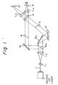
- Figure 1 illustrates a basic principle of the operation of a profile error detection on which is based a method of detecting the difference in profile of an inspected surface of an article from an analogous reference surface by using a reference hologram of the reference surface produced by a coherent beam of light, and a hologram of the inspected surface produced by using the coherent beam of light.
- a coherent beam of light L emitted from a light source is diverged and expanded by lenses L1 and L2 and is separated into a reference beam of light R and a signal beam of light S by a half mirror M0.
- the reference light beam R is reflected by a total reflection mirror M1 on a light receiving material or a photosensitive material H held at a predetermined and fixed position to form a hologram thereon.
- the signal light beam S is reflected by a total reflection mirror M2 on a surface Q of an article to be inspected, such as an industrial product.
- a specularly reflected light beam reflected from the inspected surface Q falls on the photosensitive material H held at the fixed position.
- a hologram containing the profile information of the inspected surface Q is formed on the photosensitive material H by superimposing the reference light beam R and the signal light beam S reflected from the inspected surface Q of the article.
- the hologram formed on the photosensitive material H can be used as a reference hologram.
- the reference hologram After forming the reference hologram of the reference surface Q on the photosensitive material H, the reference hologram is placed at the fixed position, and the reference surface Q is then replaced by an inspected surface Q to be compared with the selected reference surface Q, and then the reflected signal light beam S reflected from the inspected surface Q is transmitted through the reference hologram to focus the image of the inspected surface Q by a focusing lens L3 on an image plane Q′.
- interference fringes are formed on the image plane Q′ by the optical interference between a light beam diffracted by the reference hologram and the reflected light beam transmitted through the hologram.
- Profile errors in the inspected surface Q with respect to the reference surface Q are detected by an optical analysis of the interference fringes.
- the specularly reflected light beam of the signal light beam reflected from the inspected surface Q is projected onto the reference hologram instead of forming the interference fringes, then the reference hologram emits a first order diffracted light beam.
- the first order diffracted light beam is then condensed by a condenser lens L4, and then the amount of light passed through a pin-hole P is measured to detect the profile error of the inspected surface Q.
- U.S. Patent No. 4,657,396 is characterized by projecting the signal light beam on the inspected surface at a large angle of incidence to utilize the sheen effect, to enable the detection of profile errors in a machined surface, which is regarded as a rough surface from the optical point of view, such as a tooth flank of a gear.
- U.S. Patent No. 4,657,396 does not disclose the constitution of an optical mechanism practically applicable to obtain the specularly reflected light beam by separating a coherent light beam, such as a laser beam, emitted from the light source into the reference light beam and the signal light beam and projecting the signal light beam on the inspected surface at a known large angle of incidence.
- the present invention has been created to realize the practical detection of profile errors in a surface of a three dimensional article to be inspected.
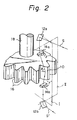
- Figure 2 is a schematic perspective view to explain a manner of projecting a signal light beam onto an inspected surface at a large angle of incidence to obtain a reflected light according to an optical profile error detecting method of the present invention
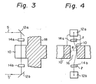
- Figs. 3 and 4 are sectional views taken on imaginary planes I and II, respectively, indicated by alternate long and two short dashes lines in Fig. 2.
- the inspected surface is a tooth surface of a gear.
- a coherent light beam for example, a laser beam, emitted from a light source, not shown, is separated into a reference beam of light R, not shown, and a signal beam of light S, and then the signal light beam S is made to travel along the imaginary plane I facing an inspected tooth surface 10 to a position directly above the inspected tooth surface 10.
- the signal light beam S is then deflected within the imaginary plane I, for example, by a total reflection mirror 12a toward a position in the vicinity of the inspected tooth surface 10 to facilitate projecting the signal light beam S onto the tooth surface 10 to be inspected.
- the signal light beam S is subsequently refracted by an optical element, such as a deflecting prism 14a, so that the direction of travel thereof is changed from the direction lying in the imaginary plane I toward a direction along another imaginary plane II which is perpendicular to the imaginary plane I, and then the signal light beam S is projected at a desired position on the inspected tooth surface 10, at a large angle ⁇ of incidence.
- the deflecting prism 14a must be finished so that the two adjacent parallelogrammatic faces thereof meet each other accurately at a vertex angle ⁇ , to allow the deflected signal light beam S to fall on the inspected tooth surface at a known large angle ⁇ of incidence and enable the use of the sheen effect.
- the signal light beam S is then reflected from the inspected tooth surface 10.
- the reflected signal light beam S passes through and is deflected by a deflecting prism 14b, i.e., the pair to the deflecting prism 14a, so as to again travel along the imaginary plane I, and then the deflected signal light beam S is reflected within the imaginary plane I, for example, by a total reflection mirror 12b to obtain a reflected signal light beam S′.
- the reflected signal light beam S′ is projected, together with the reference light beam R traveling through the other non-illustrated optical pass, onto a photosensitive material (not illustrated), held at a fixed position, such as mentioned with reference to the mechanism shown in Fig. 1 embodying the hologram producing principle, to produce the hologram of the inspected tooth surface 10.
- the signal light beam S can be projected on the inspected tooth surface 10 exactly at the large angle ⁇ of incidence. That is, the signal light beam S can be easily made to travel along the imaginary plane I even into the tooth space 16 between the two adjacent gear teeth of a gear having a plurality of gear teeth, and then the signal light beam S can be reflected or refracted within the imaginary plane II perpendicular to the imaginary plane I to make the signal light beam S fall exactly on the inspected tooth surface 10 at the large angle ⁇ of incidence.
- the tooth surfaces of the gear teeth can be sequentially located at the position of the inspected tooth surface 10 by turning the gear on the rotary shaft 18 to subject respective tooth surfaces successively to the profile error detection.
- the signal light beam S can be easily projected on the inspected tooth surface 10 regardless of whether the inspected tooth surfaces 10 are located far from or adjacent to the rotary shaft 18, without entailing mechanical interference between the optical system including the total reflection mirrors 12a and 12b and the deflecting prisms 14a and 14b, and the gear per se and the rotary shaft 18, by shifting the optical system or the gear along the imaginary plane I containing the signal light beam S and the reflected signal light beam S′ according to the size of the gear.
- the signal beam of light S in detecting profile errors in the tooth surfaces of a gear as illustrated in Figs 2 through 4, can be projected at the large angle ⁇ of incidence on a tooth surface 10′ (Fig. 4) opposite to the inspected tooth surface 10 with respect to the tooth space 16, and the reflected signal light beam S′ can be made to travel along the same original plane I when the respective directions of refraction and deflection of the deflecting prisms 14a and 14b are made opposite to each other within the imaginary plane II.
- the profile error detection of the tooth surface 10′ can be easily achieved.
- a practical arrangment and construction of the deflecting prisms 14a and 14b respectively for refracting and deflecting the signal light beam in opposite directions will be described in the following examples.
- the signal light beam S is separated into two parallel signal beams of light, i.e., into a first signal light beam S and a second signal light beam S, before entering the deflecting prism 14a on the side of incidence so that the first and second signal light beams S travel along two parallel imaginary planes I.
- the first and second light signal beams S are projected on the opposite inspected tooth surfaces 10 and 10′ by two sets of paired deflecting prisms 14a and 14b, respectively.
- the respective holograms of the two detected tooth surfaces 10 and 10′ can be successively produced or profile errors in the two inspected tooth surfaces 10 and 10′ can be successively detected.
- the combined deflecting prism 24a (24b) comprises a flat section 22a (22b) having parallel upper and lower faces, and deflecting prism sections 26a and 26a′ (26b and 26b′) each having two parallelogrammatic faces extending at the vertex angle ⁇ to each other and respectively joined to the opposite ends of the flat section 22a (22b) in opposite directions.
- the hologram of the detected tooth surface 10 can be produced or profile errors in the inspected surface 10 can be detected by employing the signal light beam S and the deflecting prism sections 26a and 26b, and the hologram of the opposite inspected tooth surface 10′ can be produced or profile errors in the inspected tooth surface 10′ can be detected by employing the same signal light beam S and the opposite deflecting prism sections 26a′ and 26b′.
- a prism assembly 34a comprising a pair of deflecting prisms 36a and 36a′ is arranged above the inspected tooth surface 10, and another prism assembly 34b comprising a pair of deflecting prisms 36b and 36b′ is arranged below the inspected tooth surface 10.
- the prism assemblies 34a and 34b are constructed so that both assemblies are synchronously turned about a vertical axis 37.
- the signal light beam S is deflected in a direction opposite to the direction of deflection when the prism assemblies 34a and 34b are located at the position (a), and thus the signal light beam can be projected onto the inspected tooth surface 10′ for reflection.
- the angle of incidence can be continuously varied between + ⁇ and - ⁇ by turning the deflecting prisms 36a and 36a′ of the prism assembly 34a relative to each other about the vertical axis 37 and turning the deflecting prisms 36b and 36b′ of the prism assembly 34b relative to each other about the vertical axis 37 to determine an optimum angle of incidence according to the surface roughness of the inspected tooth surface 10 or 10′.
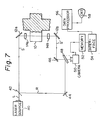
- Figure 7 is a block diagram showing a profile error detecting and analyzing system employing the arrangement of Figs. 2 through 4.
- This detecting and analyzing system executes a minute detection of profile errors over the entire area of a three-dimensional inspected surface, such as the inspected tooth surface 10 or 10′, and analyzes data obtained through the detection of profile errors by applying a conventional data processing technique using a commercially available computer system simultaneously with the optical detection of the profile errors.
- a coherent light beam such as a He-Ne laser beam emitted by a laser light source 40 is separated by a half mirror 42 into a reference light beam R and a signal light beam S.
- the signal light beam S is transmitted further through a total reflection mirror 12a and a deflecting mirror 14a and, as mentioned with reference to Figs. 2 through 4, is projected on an inspected surface 10 for regular reflection.
- a reflected signal light beam S′ reflected from the inspected surface 10 is transmitted through a deflecting prism 14b and a total reflection mirror 12b.
- the reflected signal light beam S′ is then reflected by a total reflection mirror 46 and projected onto a photosensitive material 48 held at a fixed position.
- the reference light beam R is reflected by a total reflection mirror 44 and brought to the photosensitive material 48.
- the hologram of the inspected surface 10 can be produced on the photosensitive material 48.
- the inspected surface 10 is initially replaced with a reference surface to produce the hologram of the reference surface, namely, a reference hologram, on the photosensitive material 48, and then the photosensitive material 48 is developed.
- the developed reference hologram is placed again at the same position, and then an objective inspected surface 10 is placed at the detecting position where the reference surface was placed.
- the specularly reflected light beam S′ reflected by the inspected surface 10 is projected onto the photosensitive material 48 carrying thereon the reference hologram.
- interference fringes can be taken by projecting the image of the detected surface 10, by using taking lens of an image taking device, such as a TV camera 50, onto a screen and by taking the image formed on the screen.
- the image data of the interference fringes is stored temporarily in a memory means 52 consisting of an image frame memory.
- the image data of the interference fringes stored in the memory means 52 is applied through an interface 54 to a data processor 56 for analysis to evaluate the entire area of the inspected surface in comparison with the reference profile. If necessary, the results of the analysis can be displayed, for example, on a CRT device 58 or a well-known plotting device, not shown.
- the evaluation of the entire area of the inspected surface 10 or 10′ through the analysis of the data by a computer system enhances the accuracy of determination of the functions and performance of an industrial product in which the detected surface per se, such as a tooth surface of a gear, is a mechanically operative element, and therefore is very advantageous.
- the angle ⁇ of incidence can be accurately determined by precisely producing the deflecting prisms 14a and 14b each having the vertex angle ⁇ and, since the wavelength ⁇ of the laser beam is known, the fringe sensitivity P can be determined through calculation.
- Profile error data can be obtained by using the calculated fringe sensitivity P, and the profile of the inspected surface can be corrected on the basis of the profile error data thus obtained.
- the surface of an inspected article is not necessarily parallel with the axis of the rotary shaft 18 as shown in Fig. 2. That is, the tooth surfaces of a helical gear are inclined to the axis. Therefore, in some cases, it is impossible to project the signal light beam S on the tooth surface of the gear by transmitting the signal light beam S along the imaginary plane I parallel with the axis as illustrated in Figs. 2 through 4. In such a case, it may be possible to project the signal light beam S onto the tooth surface by tilting the rotary shaft 18 so that the imaginary plane I is located opposite to the tooth of the helical gear.
- a coherent light beam L is projected from a point on a line passing the substantially middle point with respect to a tooth width of a helical gear and contained within a plane containing the axis 18′ of the helical gear.
- the coherent light beam L is separated into a reference light beam R and a signal light beam S by a half mirror 42.
- the reference light beam R is projected through total reflection mirrors 44 and 45 onto a photosensitive material 48 removably held at a fixed position.
- the signal light beam S is transmitted through total re flection mirrors 62 and 64 along an imaginary plane containing the axis 18′ of the helical gear and is projected onto a tooth surface at a large angle of incidence by a total reflection mirror 12a and a deflecting prism 14a.
- a reflected signal light beam S′ reflected from the tooth surface is deflected by a deflecting prism 14b and a total reflection mirror 12b so as to travel along the imaginary plane, and then the reflected signal light beam S′ is projected onto the photosensitive material 48 by a total reflection mirror 66.
- an optical system comprising optical elements including the mirrors 42, 44, 45, 62, 64, 66, 12a and 12b, and the deflecting prisms 14a and 14b, is constructed so as to be turned about a line of projection of the coherent light beam L in a direction indicated by an arrow ⁇
- the imaginary plane can be turned according to the helix angle of the helical gear to position the imaginary plane opposite to a tooth surface of the helical gear. Accordingly, profile errors in the teeth of the helical gear can be detected on the same principle as that explained with reference to Figs. 2 through 4 applied to detecting profile errors in the teeth of a spur gear. Since a laser light source which emits the coherent light beam may be disposed at a fixed position, the mechanism for turning the optical system can be formed with a comparatively simple construction.
- Figure 9 illustrates a modification of the mechanism of Fig. 8.
- the mechanism of Fig. 9 reflects the reflected signal light beam S′ reflected by the total reflection mirror 66 again by a total reflection mirror 68 so that the reflected signal light beam S′ travels on the same optical axis as the coherent light beam L, and then the reflected signal light beam S′ is reflected by a fixed mirror 70 so as to fall on the photosensitive material 48 (hologram) together with the reference light beam R.
- the reflected signal light beam S′ reflected from the tooth surface is transmitted so as to again travel on the same optical axis as the coherent light beam L when the optical system is turned about the optical axis of the coherent light beam L thereby allowing the signal light beam S to travel along the imaginary plane facing the tooth surface of the helical gear, the reflected signal light beam S′ can be transmitted on the same axis regardless of the angle of turning of the optical system. Since the reflected signal light beam S′ is reflected by the fixed mirror 70 on the photosensitive material 48 (hologram), an optical system for transmitting the reference light beam R and the photosensitive material 48 may be fixedly disposed.
- a camera i.e., means for taking interference fringes, provided behind the photosensitive material 48, and the data processing system may be arranged at fixed positions, respectively, as a matter of course.
- the mechanism for turning the optical system of the mechanism illustrated in Fig. 9 can be simpler in construction than that of the mechanism of Fig. 8.
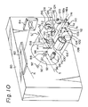
- Figure 10 is a perspective view of a profile error detecting apparatus for optically detecting profile errors in a surface of an article to be inspected according to a preferred embodiment of the present invention.
- This optical profile error detecting apparatus has the afore-described arrangement (1) to successivelysively carry out an optical inspection of two consecutive surfaces for detecting profile errors in the two inspected surfaces.
- a reference light beam R separated from a coherent beam of light is reflected on a holographic dry plate (or a photosensitive material) 84 by a reflecting mirror 82 stationarily held on a fixed frame 80.
- the hologram of a reference surface analogous with the inspected surfaces is recorded on the holographic dry plate 84.
- a signal beam of light S is reflected by a reflecting mirror 88 fixedly mounted on a bracket fixed to the fixed frame 80 so as to travel along the central axis 90 of rotation of a hollow cylindrical support element 86.
- the support element 86 is a rigid member for supporting optical systems and is rotatably supported by rotational bearings 92.
- the signal light beam S entering into the support element 86 is first reflected by small mirrors 94 and 96 and subsequently expanded by light beam expanding lenses 98 and 100.
- the expanded signal light beam S is further reflected sequentially by reflecting mirrors 102 and 104 so as to travel toward an inspected article 120.
- the signal light beam S When reflected by the reflecting mirror 104, the signal light beam S is separated into two signal light beams S1 and S2 by a half mirror 106.
- the signal light beam S1 is reflected by a reflecting mirror 108 toward a deflecting prism 110
- the signal light beam S2 is reflected by reflecting mirrors 112 and 114 toward a deflecting prism 116.
- the optical elements defining optical paths of the signal light beams S, S1 and S2 extending from the reflecting mirror 88 to the reflecting mirrors 108 and 114 are the components of an optical system for separating the light signal beam S into the light signal beams S1 and S2 and for transmitting the signal light beams S1 and S2 so that the signal light beams S1 and S2 travel finally along two parallel imaginary planes, not shown, extending opposite two inspected surfaces 118a and 118b of the inspected article 120, respectively.
- the deflecting prisms 110 and 116 are the components of an optical system for deflecting the signal light beams S1 and S2 in a direction perpendicular to the imaginary planes to project the signal light beams S1 and S2 respectively on the inspected surfaces 118a and 118b at a large angle of incidence suitable for utilizing the sheen phenomenon.
- the respective signal light beams S1 and S2 specularly reflected by the inspected surfaces 118a and 118b are subsequently deflected by deflecting prisms 122 and 124 in reflected signal light beams S1′ and S2′ so as to travel along the same imaginary planes, respectively.
- the reflected signal light beams S1′ and S2′ are transmitted through predetermined optical paths defined by reflecting mirrors 126 through 142 and, finally, are reflected by a reflecting mirror 144 fixedly provided at a fixed position separate from the support element 86 on the photosensitive material 84.
- a reference hologram namely, the hologram of a reference surface
- the inspected surface 118a is irradiated by the signal light beam S1 and then the other inspected surface 118b is irradiated by the signal light beam S2 to detect profile errors in these surfaces 118a and 118b sequentially by forming the respective interference fringes of the inspected surfaces 118a and 118b on a screen, not shown, taking the interference fringes and, as mentioned above, analyzing the interference fringes by a computer system.
- the holograms of both inspected surfaces 118a and 118b can be recorded simultaneously on the photosensitive material 84.
- the inspected article is a gear
- profile errors in the tooth surfaces of a helical gear are inspected and detected, it is possible to set the two imaginary planes respectively accurately opposite to inspected surfaces without tilting the axis of the helical gear, only by turning the cylindrical support element 86 about the central axis 90 of rotation through an appropriate angle to tilt the imaginary planes at an angle corresponding to the helix angle of the helical gear.
- a rotative driving means for turning the rotary support element 86 may employ a conventional rotary stepping motor or a conventional linear stepping motor.
- a linear stepping motor When a linear stepping motor is employed, a wire or rope having one end fixed to the moving element of the linear stepping motor is wound around the support element 86 to rotate the cylindrical support element 86. The other end of the rope is attached to the fixed frame 80.
- the deflecting prisms 110 and 122 and the reflecting mirrors 126 and 134 is arranged in a plane X1 indicated by alternate long and two short dashes lines in Fig. 11, and when the optical system defining the optical paths for the signal light beam S2 which comprises the reflecting mirrors 112 and 114, the deflecting prisms 116 and 124 and the reflecting mirrors 128 and 132 are arranged in a plane X2 indicated by alternate long and two short dashes lines in Fig.
- the deflecting prisms 110 and 122 and the reflecting mirror 126 of the optical system for the signal light beam S1 are arranged in a plane Y1 indicated by alternate long and two short dashes lines in Fig. 12 and the reflecting mirror 114, the deflecting prisms 116 and 124 and the reflecting mirror 128 of the optical system for the signal light beam S2 are arranged in a plane Y2 indicated by alternate long and two short dashes lines in Fig.
- the paths of travel of the separated signal light beams S1 and S2 falling on and being reflected by the inspected surfaces 118a and 118b can be adjusted according to the variation of a distance M by moving the above-mentioned planes X1 and X2 respectively toward and away from the inspected surfaces 118a and 118b.
- the signal light beams S1 and S2 can be projected onto the inspected surfaces 118a and 118b at the same three-dimensional positions by moving the above-mentioned planes Y1 and Y2 relative to each other to adjust a distance N.
- the signal light beams S1 and S2 can be projected respectively at optimum detecting positions on the surfaces 118a and 118b to obtain profile error data of these inspected surfaces.
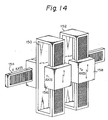
- Figure 14 shows an embodiment of an actuating means for moving the planes X1 , X2 , Y1 and Y2 illustrated in Figs. 11 and 12.
- two columns 150 and 152 are laterally slidably mounted on a fixed lateral girder 154 so as to be moved laterally toward and away from each other on a known linear stepping motor system, and two supporting members 156 and 158 are mounted respectively on the columns 150 and 152 so as to be moved vertically relative to the columns 150 and 152 on another known linear stepping motor system.
- the columns 150 and 152 correspond to the planes X1 and X2 of Fig.
- the supporting members 156 and 158 correspond to the planes Y1 and Y2 of Fig. 11, respectively.
- the movement of the planes X1 , X2 , Y1 and Y2 can be precisely controlled on the operational principle of the linear stepping motor system.
- Figure 15 is a perspective view of an optical profile error detecting apparatus for detecting profile errors in surfaces to be inspected, which is basically constructed on the basis of the arrangement and construction of Figs. 10 through 14, and is adopted as a tooth profile error detecting apparatus.
- the tooth profile error detecting apparatus has a bed 200.
- a mandrel 202 supporting a gear 204 to rotate the same about the axis thereof is supported on the bed 200 by a bracket 203 attached to a column 201 fixedly mounted on the bed 200.
- the mandrel 202 is rotated through an indexing mechanism 205 by a servomotor Sm provided within the bed 200.
- a conventional rotary encoder 206 is arranged so as to cooperate with the indexing mechanism 205 for detecting the angular motion of the mandrel 202.
- the angular motion of the mandrel 202, and thus the angle of rotation of the gear 204, detected by the encoder 206 is transmitted via an interface 208 to an electronic computer system 210 consisting of a commercially available electronic micro computer.
- the computer system 210 controls the angle of rotation of the gear 204 on the basis of the data given thereto to index each inspected tooth surface of the gear 204 automatically sequentially at the detecting position.
- a profile error detecting unit 220 is supported on a base block 222 which is mounted on the bed 200 at a position opposite to the mandrel 202.
- the base block 222 supporting the profile error detecting unit 220 is driven, for example, by a known driving mechanism employing a linear stepping motor for sliding movement toward and away from the mandrel 202 supporting the detected gear 204 along the upper surface of the bed 200 in directions indicated by a double-head arrow X.
- a detecting head supporting block 226 is supported on the base block 222 and is driven by a driving mechanism employing a linear stepping motor for vertical sliding movement in directions indicated by a double-head arrow Y.
- a rotary detecting head 228 is mounted on the detecting head supporting block 226.
- An optical detecting mechanism having the columns 150 and 152 and the supporting members 156 and 158 illustrated in Fig. 14, which support the optical systems and are driven by linear stepping motors, is accommodated inside the rotary detecting head 228.
- the rotary detecting head 228 corresponds to the rotary cylindrical support element 86 of Fig. 10 in function. Some deflecting prisms of the optical detecting mechanism project from the rotary detecting head 228 near to the inspected gear 204.
- a He-Ne laser source 234 provided within the bed 200 generates a laser beam as a coherent inspecting beam of light.
- the laser beam is deflected by a plurality of reflecting mirrors 236 and is separated into a reference light beam R and a signal light beam S by a half mirror 238.
- the signal light beam S is led to the optical detecting mechanism provided within the rotary head 228. Then, the optical detecting mechanism carries out the optical detection of three-dimensional profile errors in the tooth surfaces of the gear 204, i.e., the inspected article, on the basis of the aforesaid profile error detection principle.
- the reference light beam R transmitted through appropriate optical paths is reflected by a reflecting mirror 240 corresponding to the reflecting mirror 82 of Fig. 10 on a photosensitive material 242 corresponding to the photosensitive material 84 of Fig. 10.
- the signal light beam S emitted from the optical detecting mechanism falls on the photosensitive material 242.
- interference fringes are formed on the
- the interference fringes can be taken by a camera 244, and fringe data representing the interference fringes is stored temporarily in a frame memory 212.
- the fringe data is given through an interface 208 from the frame memory 212 to the computer system 210 for analysis.
- An exposure unit 216 is provided for producing a hologram of each inspected tooth surface.
- the results of analysis of the fringe data can be displayed on a CRT display 214 or can be copied in a hard copy by a copying unit, not shown.
- the camera 244 is provided with an optical sensor 246 for detecting the quantity of first order diffracted light diffracted by the hologram recorded on the photosensitive material 242.
- the tooth profile error detecting apparatus in this embodiment is capable of detecting the three-dimensional profile of the tooth surfaces with reference to the hologram of a reference tooth surface irrespective of the form of gears, such as spur gears and helical gears, size or module of teeth and size of gears.
- gears such as spur gears and helical gears, size or module of teeth and size of gears.
- Indicated at 248 in Fig. 15 are pneumatic dampers for preventing the influence of external disturbance such as external vibrations on the tooth profile error detecting apparatus.
- the tooth profile error detecting apparatus is housed in a large casing 250 having a door to prevent the influence of an optical external disturbance on the tooth profile error detecting apparatus.
Landscapes
- Physics & Mathematics (AREA)
- General Physics & Mathematics (AREA)
- Length Measuring Devices By Optical Means (AREA)
Applications Claiming Priority (2)
| Application Number | Priority Date | Filing Date | Title |
|---|---|---|---|
| JP62273492A JP2557911B2 (ja) | 1987-10-30 | 1987-10-30 | 被検面の形状誤差の光学的検出装置 |
| JP273492/87 | 1987-10-30 |
Publications (2)
| Publication Number | Publication Date |
|---|---|
| EP0321639A1 true EP0321639A1 (de) | 1989-06-28 |
| EP0321639B1 EP0321639B1 (de) | 1992-01-02 |
Family
ID=17528657
Family Applications (1)
| Application Number | Title | Priority Date | Filing Date |
|---|---|---|---|
| EP88108827A Expired - Lifetime EP0321639B1 (de) | 1987-10-30 | 1988-06-01 | Vorrichtung zum Erfassen des Profilfehlers der Oberfläche eines Artikels |
Country Status (4)
| Country | Link |
|---|---|
| US (1) | US4910561A (de) |
| EP (1) | EP0321639B1 (de) |
| JP (1) | JP2557911B2 (de) |
| DE (1) | DE3867452D1 (de) |
Cited By (3)
| Publication number | Priority date | Publication date | Assignee | Title |
|---|---|---|---|---|
| DE10303364A1 (de) * | 2003-01-29 | 2004-08-05 | Hentze-Lissotschenko Patentverwaltungs Gmbh & Co.Kg | Vorrichtung zur Bestimmung des Höhenprofils eines Objekts |
| CN112304240A (zh) * | 2020-10-19 | 2021-02-02 | 西安工程大学 | 一种基于激光干涉法的斜齿轮齿面形貌测量光路及方法 |
| US11371836B2 (en) * | 2015-11-02 | 2022-06-28 | DWFritz Automation, Inc. | Device for the contactless three-dimensional inspection of a mechanical component with toothing |
Families Citing this family (6)
| Publication number | Priority date | Publication date | Assignee | Title |
|---|---|---|---|---|
| JP2002350128A (ja) * | 2001-05-30 | 2002-12-04 | Canon Inc | 立体形状計測装置並びに立体形状計測方法および位置合わせ方法 |
| US20090071278A1 (en) * | 2007-09-18 | 2009-03-19 | Hiwin Technologies Corp. | Ball screw device having image sensor |
| DE102011086267A1 (de) * | 2011-11-14 | 2013-05-16 | Siemens Aktiengesellschaft | System und Verfahren zur Steuerung eines thermografischen Messvorganges |
| JP6474310B2 (ja) * | 2015-05-08 | 2019-02-27 | 株式会社ミツトヨ | 非接触距離測定方法 |
| CN111226089A (zh) * | 2017-10-23 | 2020-06-02 | 格里森计量系统股份有限公司 | 使用非接触式传感器在复合机器测试平台上测量带齿物品 |
| US12385736B2 (en) * | 2020-11-20 | 2025-08-12 | Gleason Metrology Systems Corporation | Automated noncontact sensor positioning |
Citations (2)
| Publication number | Priority date | Publication date | Assignee | Title |
|---|---|---|---|---|
| US3735036A (en) * | 1970-10-26 | 1973-05-22 | Express I M Co | Real time interferometry contour mapping system |
| US4197010A (en) * | 1977-01-17 | 1980-04-08 | Agence Nationale De Valorisation De La Recherche (Anvar) | Length standard comparison method and apparatus utilizing holographic interferrometry |
Family Cites Families (3)
| Publication number | Priority date | Publication date | Assignee | Title |
|---|---|---|---|---|
| JPS566550B2 (de) * | 1973-01-20 | 1981-02-12 | ||
| JPS60200112A (ja) * | 1984-03-23 | 1985-10-09 | Osaka Seimitsu Kikai Kk | 光学的形状誤差検出法 |
| US4624568A (en) * | 1985-04-11 | 1986-11-25 | Eaton Corporation | Holographic test method for rotational effects on gears |
-
1987
- 1987-10-30 JP JP62273492A patent/JP2557911B2/ja not_active Expired - Fee Related
-
1988
- 1988-06-01 EP EP88108827A patent/EP0321639B1/de not_active Expired - Lifetime
- 1988-06-01 DE DE8888108827T patent/DE3867452D1/de not_active Expired - Lifetime
- 1988-06-06 US US07/202,609 patent/US4910561A/en not_active Expired - Lifetime
Patent Citations (2)
| Publication number | Priority date | Publication date | Assignee | Title |
|---|---|---|---|---|
| US3735036A (en) * | 1970-10-26 | 1973-05-22 | Express I M Co | Real time interferometry contour mapping system |
| US4197010A (en) * | 1977-01-17 | 1980-04-08 | Agence Nationale De Valorisation De La Recherche (Anvar) | Length standard comparison method and apparatus utilizing holographic interferrometry |
Cited By (3)
| Publication number | Priority date | Publication date | Assignee | Title |
|---|---|---|---|---|
| DE10303364A1 (de) * | 2003-01-29 | 2004-08-05 | Hentze-Lissotschenko Patentverwaltungs Gmbh & Co.Kg | Vorrichtung zur Bestimmung des Höhenprofils eines Objekts |
| US11371836B2 (en) * | 2015-11-02 | 2022-06-28 | DWFritz Automation, Inc. | Device for the contactless three-dimensional inspection of a mechanical component with toothing |
| CN112304240A (zh) * | 2020-10-19 | 2021-02-02 | 西安工程大学 | 一种基于激光干涉法的斜齿轮齿面形貌测量光路及方法 |
Also Published As
| Publication number | Publication date |
|---|---|
| US4910561A (en) | 1990-03-20 |
| DE3867452D1 (de) | 1992-02-13 |
| EP0321639B1 (de) | 1992-01-02 |
| JP2557911B2 (ja) | 1996-11-27 |
| JPH01116403A (ja) | 1989-05-09 |
Similar Documents
| Publication | Publication Date | Title |
|---|---|---|
| US4122525A (en) | Method and apparatus for profile scanning | |
| JP3970998B2 (ja) | 電動スキャニングテーブル付き共焦点顕微鏡 | |
| US4330775A (en) | Apparatus for inspecting defects in a periodic pattern | |
| EP1062478B8 (de) | Vorrichtung und verfahren für eine optische oberflächenkonturmessung | |
| US5327218A (en) | Method and apparatus for measuring displacement by using a diffracted inverted image projected on a diffraction grating | |
| US8614790B2 (en) | Optical system and method for inspection of patterned samples | |
| US6424735B1 (en) | High precision three dimensional mapping camera | |
| EP0321639A1 (de) | Vorrichtung zum Erfassen des Profilfehlers der Oberfläche eines Artikels | |
| CN1138896A (zh) | 测量偏心转动件的方法和装置 | |
| US5684596A (en) | Method and apparatus for measuring axial and torsional loads on a valve stem | |
| US4452534A (en) | Method of determining geometric parameters of object's surface and device therefor | |
| JP3495783B2 (ja) | エンコーダ | |
| EP0060685B1 (de) | Verfahren zur Deformationsmessung | |
| US5004345A (en) | Dual-lens shearing interferometer | |
| US7342654B2 (en) | Detection of impurities in cylindrically shaped transparent media | |
| KR100434445B1 (ko) | 3차원 형상/표면조도 측정장치 | |
| EP1644699B1 (de) | Verfahren und vorrichtungen zur verringerung von fehlern bei interferrometrischen abbildungsmessungen | |
| US3883249A (en) | Z-factor and other diffractographic displacement and profile sensors | |
| JPH0786411B2 (ja) | 歯車の歯面形状の非接触測定方法 | |
| EP0486050B1 (de) | Verfahren und Vorrichtung zum Messen von Verschiebungen | |
| US3917409A (en) | Optical apparatus for determining focus | |
| CN1039157C (zh) | 微机调控干涉云纹仪 | |
| JPH04258709A (ja) | 非接触自由曲面測定装置による歯車の歯面形状測定方法 | |
| JP3728310B2 (ja) | エンコーダ | |
| SU798567A1 (ru) | Устройство дл контрол дефектовпОВЕРХНОСТи ТЕл ВРАщЕНи |
Legal Events
| Date | Code | Title | Description |
|---|---|---|---|
| PUAI | Public reference made under article 153(3) epc to a published international application that has entered the european phase |
Free format text: ORIGINAL CODE: 0009012 |
|
| AK | Designated contracting states |
Kind code of ref document: A1 Designated state(s): CH DE GB LI |
|
| 17P | Request for examination filed |
Effective date: 19890811 |
|
| 17Q | First examination report despatched |
Effective date: 19891213 |
|
| GRAA | (expected) grant |
Free format text: ORIGINAL CODE: 0009210 |
|
| AK | Designated contracting states |
Kind code of ref document: B1 Designated state(s): CH DE GB LI |
|
| PG25 | Lapsed in a contracting state [announced via postgrant information from national office to epo] |
Ref country code: CH Effective date: 19920102 Ref country code: LI Effective date: 19920102 |
|
| REF | Corresponds to: |
Ref document number: 3867452 Country of ref document: DE Date of ref document: 19920213 |
|
| REG | Reference to a national code |
Ref country code: CH Ref legal event code: PL |
|
| PLBE | No opposition filed within time limit |
Free format text: ORIGINAL CODE: 0009261 |
|
| STAA | Information on the status of an ep patent application or granted ep patent |
Free format text: STATUS: NO OPPOSITION FILED WITHIN TIME LIMIT |
|
| 26N | No opposition filed | ||
| REG | Reference to a national code |
Ref country code: GB Ref legal event code: IF02 |
|
| PGFP | Annual fee paid to national office [announced via postgrant information from national office to epo] |
Ref country code: DE Payment date: 20070628 Year of fee payment: 20 |
|
| PGFP | Annual fee paid to national office [announced via postgrant information from national office to epo] |
Ref country code: GB Payment date: 20070620 Year of fee payment: 20 |
|
| REG | Reference to a national code |
Ref country code: GB Ref legal event code: PE20 Expiry date: 20080531 |
|
| PG25 | Lapsed in a contracting state [announced via postgrant information from national office to epo] |
Ref country code: GB Free format text: LAPSE BECAUSE OF EXPIRATION OF PROTECTION Effective date: 20080531 |