EP0321710B1 - Silo pour des produits en vrac - Google Patents
Silo pour des produits en vrac Download PDFInfo
- Publication number
- EP0321710B1 EP0321710B1 EP88119411A EP88119411A EP0321710B1 EP 0321710 B1 EP0321710 B1 EP 0321710B1 EP 88119411 A EP88119411 A EP 88119411A EP 88119411 A EP88119411 A EP 88119411A EP 0321710 B1 EP0321710 B1 EP 0321710B1
- Authority
- EP
- European Patent Office
- Prior art keywords
- silo
- base
- tunnel
- venting
- discharge chamber
- Prior art date
- Legal status (The legal status is an assumption and is not a legal conclusion. Google has not performed a legal analysis and makes no representation as to the accuracy of the status listed.)
- Expired - Lifetime
Links
- 239000013590 bulk material Substances 0.000 title claims description 3
- 238000013022 venting Methods 0.000 claims description 18
- 239000000463 material Substances 0.000 claims description 16
- 238000005273 aeration Methods 0.000 claims description 7
- 230000002093 peripheral effect Effects 0.000 claims description 6
- 238000000034 method Methods 0.000 claims description 3
- 238000009423 ventilation Methods 0.000 description 44
- 238000000605 extraction Methods 0.000 description 15
- 238000010276 construction Methods 0.000 description 1
- 230000001419 dependent effect Effects 0.000 description 1
- 230000000630 rising effect Effects 0.000 description 1
Images
Classifications
-
- B—PERFORMING OPERATIONS; TRANSPORTING
- B65—CONVEYING; PACKING; STORING; HANDLING THIN OR FILAMENTARY MATERIAL
- B65D—CONTAINERS FOR STORAGE OR TRANSPORT OF ARTICLES OR MATERIALS, e.g. BAGS, BARRELS, BOTTLES, BOXES, CANS, CARTONS, CRATES, DRUMS, JARS, TANKS, HOPPERS, FORWARDING CONTAINERS; ACCESSORIES, CLOSURES, OR FITTINGS THEREFOR; PACKAGING ELEMENTS; PACKAGES
- B65D88/00—Large containers
- B65D88/54—Large containers characterised by means facilitating filling or emptying
- B65D88/72—Fluidising devices
-
- B—PERFORMING OPERATIONS; TRANSPORTING
- B01—PHYSICAL OR CHEMICAL PROCESSES OR APPARATUS IN GENERAL
- B01F—MIXING, e.g. DISSOLVING, EMULSIFYING OR DISPERSING
- B01F33/00—Other mixers; Mixing plants; Combinations of mixers
- B01F33/40—Mixers using gas or liquid agitation, e.g. with air supply tubes
- B01F33/4092—Storing receptacles provided with separate mixing chambers
Definitions
- the invention relates to a silo for bulk material according to the preamble of claim 1.
- a bulk goods silo according to the preamble of claim 1 is known for example from AT-C-303 625.
- the venting device connected to the central extraction chamber is formed here by a pipeline which runs from the tip of the conical extraction chamber centrally through the interior of the silo to the silo ceiling.
- a disadvantage of such a design is the considerable mechanical stress to which this ventilation line is exposed through the material in the silo.
- the prior art also includes silos (DE-B-25 39 753 and DE-A-27 27 499), in which the material is discharged from the central discharge chamber via a discharge chamber leading radially from the discharge chamber to the peripheral wall of the silo which is also the ventilation of the trigger chamber.
- a vent line leads from this emptying chamber on the peripheral wall of the silo to a dedusting device or to the upper part of the silo interior.
- the invention is therefore based on the object, avoiding these disadvantages of the known designs, a silo according to the preamble of claim 1 so that despite simple construction and avoidance of undesirable mechanical stresses of the ventilation device, a uniform flow over the entire circumference of the material from the silo interior to the central deduction chamber is guaranteed.
- the ventilation device contains a ventilation tunnel which is known per se and leads from the discharge chamber to the peripheral wall of the silo and is connected to a ventilation line.
- the side walls of this ventilation tunnel have openings through which the material from the silo interior, the ventilation tunnel and through this the central extraction chamber inflows.
- the venting tunnel thus also allows goods to be transported to the central discharge chamber and in this way ensures uniform, rotationally symmetrical loading of the central discharge chamber.
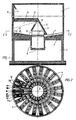
- the bulk goods silo illustrated in the drawing contains a silo room 1 for receiving the bulk goods and a room 2 for receiving further conveying devices.
- the bottom 3 of the silo room 1 is arranged in a known manner inclined towards the center and provided with pneumatic ventilation devices 4.
- a discharge chamber 5 is arranged centrally above the floor 3 and is enclosed by a conical hood 6. At the lower edge of the hood 6, openings 7 are provided through which material enters the central discharge chamber 5 from the silo space 1.
- the trigger chamber 5 extends through the Floor 3 through and is provided in its lower area with Gutausöffötechnisch 8.
- a ventilation device is connected to the extraction chamber 5, which contains a ventilation tunnel 10 arranged on the silo bottom 3 and leading from the extraction chamber 5 to the peripheral wall 9 of the silo, to which a ventilation line 11 is connected, which leads to the upper part of the silo space 1.
- the ventilation tunnel 10 provided with a rider-like cover 12 has openings 13 in its side walls, through which material enters the ventilation tunnel 10 from the silo space 1 and flows into the extraction chamber 5 through this ventilation tunnel.
- the ventilation tunnel 10 is connected to the extraction chamber 5 on the one hand via a ventilation opening 14 located in the upper region of the extraction chamber and on the other hand is connected to the extraction chamber 5 via a material outlet opening 15 which lies directly above the floor 3 of the silo.
- the bottom of the ventilation tunnel 10 is provided with pneumatic ventilation devices 16, which serve to feed the material to the extraction chamber 5 through the openings 13 from the silo space 1 into the ventilation tunnel 10.
- pneumatic ventilation devices 16 serve to feed the material to the extraction chamber 5 through the openings 13 from the silo space 1 into the ventilation tunnel 10.
- the floor 3 of the silo space is also provided directly in front of the openings 13 of the ventilation tunnel 10 with pneumatic ventilation devices 17a, 17b.
- lateral ventilation devices 16a, 16b are also provided in the bottom of the ventilation tunnel 10 and are arranged in the region of the openings 13.
- the operation of the silo is advantageously carried out as follows according to the method according to the invention: There are two separate blowers, of which the first blower is used to ventilate the central discharge chamber 5 and the second blower is used to ventilate the silo bottom 3 and the venting tunnel 10.
- the first blower continuously ventilates the central discharge chamber 5 and the second blower alternately either the silo floor 3 or the ventilation tunnel 10. In detail, this is done as follows: The level in the central discharge chamber 5 has dropped to a minimum value, so that the ventilation pressure of the central discharge chamber 5 is set If the minimum value is reached, the ventilation of the ventilation devices 16 of the ventilation tunnel 10 is switched off and the ventilation of the silo bottom 3 is switched on. For this purpose, for example, two channels lying opposite one another can be ventilated with their ventilation devices 4. During the subsequent filling of the central extraction chamber 5, the air from the ventilation of the central extraction chamber and the air from the silo ventilation as well as the air displaced from the central extraction chamber by the rising fill level are discharged via the ventilation tunnel 10.
- the aeration of the silo floor is switched off and the aeration devices 16 of the Vent tunnel 10 turned on.
- the material that has entered the venting tunnel 10 during the filling of the central extraction chamber 5 is reliably guided or returned to the central extraction chamber.
- the lateral ventilation devices 16a, 16b arranged in the venting tunnel 10 in the area of the product inlet openings 13 are combined with the pneumatic ventilation devices 17a, 17b located outside the ventilation tunnel 10 in front of the product inlet openings 13. These ventilation devices 16a, 16b, 17a, 17b are operated simultaneously with the ventilation devices of the opposite sector of the silo floor 3.
Landscapes
- Chemical & Material Sciences (AREA)
- Chemical Kinetics & Catalysis (AREA)
- Engineering & Computer Science (AREA)
- Mechanical Engineering (AREA)
- Filling Or Emptying Of Bunkers, Hoppers, And Tanks (AREA)
- Storage Of Harvested Produce (AREA)
Claims (7)
- Silo de matière en vrac, comprenant :a) un fond (3) équipé de dispositifs pneumatiques (4) d'aération,b) une chambre (5) de soutirage disposée centralement sur le fond (3) du silo et dont la paroi circonférentielle comporte des trous (7) d'entrée de matière,c) un trou de décharge de matière disposé centralement dans le fond (3) du silo,d) un dispositif de ventilation (10, 11) raccordé à la chambre de soutirage (5),
caractérisé par la particularité suivante :a) le dispositif de ventilation comprend un tunnel (10) disposé sur le fond (3) du silo, allant de la chambre centrale (5) de soutirage à la paroi circonférentielle (9) du silo, raccordé à un conduit de ventilation (11) et dont les parois latérales comportent des trous (13) d'entrée de matière. - Silo selon la revendication 1, caractérisé en ce que le fond du tunnel de ventilation (10) est équipé de dispositifs pneumatiques (16) d'aération.
- Silo selon la revendication 1, caractérisé en ce que le fond (3) du silo qui se trouve à l'extérieur du tunnel de ventilation (10), devant les trous (13) d'entrée de matière, est équipé de dispositifs pneumatiques (17a, 17b) d'aération.
- Silo selon la revendication 1, caractérisé en ce que le tunnel de ventilation (10), qui est équipé d'une couverture (12) en forme de traverse, communique avec la chambre de soutirage (5) d'une part par un trou de ventilation (14) situé à la partie supérieure de la chambre de soutirage et d'autre part par un trou (15) de décharge de matière disposé immédiatement au-dessus du fond (3) du silo.
- Silo selon la revendication 2, caractérisé en ce que le fond du tunnel de ventilation (10) comprend, en plus des dispositifs d'aération (13) disposés au milieu, des dispositifs latéraux d'aération (16a, 16b) qui sont disposés à proximité des trous (13).
- Procédé d'exploitation d'un silo selon les revendications 1 et 2, caractérisé par les particularités suivantes :a) deux soufflantes séparées sont utilisées, dont la première sert à l'aération de la chambre centrale de soutirage (5) et la seconde soufflante sert à l'aération du fond (3) du silo et du tunnel de ventilation (10) ;b) les deux soufflantes sont en permanence en service pendant l'exploitation du silo ;c) la seconde soufflante aère en alternance le fond (3) du silo et le tunnel de ventilation (10), l'aération du fond du silo étant enclenchée lorsque le niveau de remplissage de la chambre centrale (5) de soutirage est tombé à un minimum, tandis que l'aération du fond du silo est coupée et l'aération du tunnel de ventilation (10) est mise en service lorsque le niveau de remplissage de la chambre centrale (5) de soutirage atteint un maximum.
- Procédé selon la revendication 6 d'exploitation d'un silo selon les revendications 1,2, 3 et 5, caractérisé en ce que les dispositifs latéraux d'aération (16a, 16b) disposés dans le tunnel de ventilation (10), à proximité des trous (13) d'entrée de matière, sont mis en service avec les dispositifs (17a, 17b) d'aération du fond (3) du silo qui se trouvent à l'extérieur du tunnel de ventilation (10), devant les trous (13) d'entrée de matière.
Applications Claiming Priority (2)
| Application Number | Priority Date | Filing Date | Title |
|---|---|---|---|
| DE3743637 | 1987-12-22 | ||
| DE19873743637 DE3743637A1 (de) | 1987-12-22 | 1987-12-22 | Silo fuer schuettgut |
Publications (2)
| Publication Number | Publication Date |
|---|---|
| EP0321710A1 EP0321710A1 (fr) | 1989-06-28 |
| EP0321710B1 true EP0321710B1 (fr) | 1993-02-03 |
Family
ID=6343318
Family Applications (1)
| Application Number | Title | Priority Date | Filing Date |
|---|---|---|---|
| EP88119411A Expired - Lifetime EP0321710B1 (fr) | 1987-12-22 | 1988-11-22 | Silo pour des produits en vrac |
Country Status (4)
| Country | Link |
|---|---|
| US (1) | US4930943A (fr) |
| EP (1) | EP0321710B1 (fr) |
| DE (2) | DE3743637A1 (fr) |
| ES (1) | ES2037186T3 (fr) |
Cited By (1)
| Publication number | Priority date | Publication date | Assignee | Title |
|---|---|---|---|---|
| CN105438854A (zh) * | 2014-08-26 | 2016-03-30 | 潞城市卓越水泥有限公司 | 一种稳流仓布料装置 |
Families Citing this family (3)
| Publication number | Priority date | Publication date | Assignee | Title |
|---|---|---|---|---|
| WO2004023242A2 (fr) * | 2002-09-03 | 2004-03-18 | South, Phillip, Barry | Terminal de transfert avec tremie intermediaire |
| DE10261292B4 (de) * | 2002-12-27 | 2006-09-14 | Eisenmann Maschinenbau Gmbh & Co. Kg | Vorlagebehälter für pulverförmige Medien |
| DE10261276B4 (de) * | 2002-12-27 | 2005-12-01 | Eisenmann Maschinenbau Gmbh & Co. Kg | Vorlagebehälter für pulverförmige Medien |
Family Cites Families (21)
| Publication number | Priority date | Publication date | Assignee | Title |
|---|---|---|---|---|
| DE303625C (fr) * | ||||
| US3260389A (en) * | 1962-03-23 | 1966-07-12 | Granu Flow Equipment Ltd | Container-emptying clamp stand with gas-fluidizing cap |
| AT303625B (de) * | 1969-07-25 | 1972-12-11 | Peters Ag Claudius | Verfahren zum Mischen von Schüttgut in einem Mischsilo |
| DE2436414C2 (de) * | 1974-07-29 | 1975-11-06 | Claudius Peters Ag, 2000 Hamburg | Verfahren zum Betrieb einer Vorrichtung zum Mischen von Schüttgut |
| DE2508981A1 (de) * | 1975-03-01 | 1976-09-09 | Peters Ag Claudius | Verfahren und vorrichtung zur regelung der auflockerungsluftmenge in einer vorrichtung zum mischen von schuettgut |
| GB1511957A (en) * | 1975-07-23 | 1978-05-24 | Polysius Ag | Container base for the pneumatic discharge of fine material |
| DE2539753C2 (de) * | 1975-09-06 | 1986-10-02 | Claudius Peters Ag, 2000 Hamburg | Mischsilo für Schüttgut |
| DE2547667B2 (de) * | 1975-10-24 | 1978-07-20 | Portland-Zementwerke Heidelberg Ag, 6900 Heidelberg | Silo, insbesondere Großraumsilo für mehlförmige Schüttgüter |
| DE2619993B2 (de) * | 1976-05-06 | 1981-02-12 | Claudius Peters Ag, 2000 Hamburg | Verfahren zur Entnahme von Schüttgut aus einem bodenbelüfteten Silo sowie Entnahmevorrichtung zur Durchführung des Verfahrens |
| DE2727499B2 (de) * | 1977-06-18 | 1980-11-13 | Claudius Peters Ag, 2000 Hamburg | Misch- oder Homogenisierkammer in einem Silo |
| US4375335A (en) * | 1977-06-30 | 1983-03-01 | Klein Albenhausen Heinrich | Silo combination for mixing stored material |
| DE2744853A1 (de) * | 1977-10-05 | 1979-04-12 | Polysius Ag | Behaelterboden zum pneumatischen austrag von feingut |
| DE2827991C2 (de) * | 1978-06-26 | 1988-01-21 | Claudius Peters Ag, 2000 Hamburg | Schüttgutsilo mit Mischkammer |
| DE2949791A1 (de) * | 1979-12-11 | 1981-06-19 | Krupp Polysius Ag, 4720 Beckum | Vorrats- und mischsilo fuer schuettgut |
| DE3040750A1 (de) * | 1980-10-29 | 1982-06-03 | Claudius Peters Ag, 2000 Hamburg | Silo fuer schuettgut |
| DE3302134A1 (de) * | 1983-01-22 | 1984-07-26 | Vtg Vereinigte Tanklager Und Transportmittel Gmbh, 2000 Hamburg | Sicherheitsabschluss fuer die belueftungsleitung von kesselwagen |
| DE3314329A1 (de) * | 1983-04-20 | 1984-10-25 | Krupp Polysius Ag, 4720 Beckum | Silo fuer mehlfoermiges schuettgut |
| DE3409898A1 (de) * | 1984-03-17 | 1985-09-19 | Linke-Hofmann-Busch, Waggon-Fahrzeug-Maschinen Gmbh, 3320 Salzgitter | Kesselwagen oder tank mit sicherheitsabschluss fuer die entlueftungsleitung |
| DD232475A1 (de) * | 1984-05-18 | 1986-01-29 | Dessau Zementanlagenbau Veb | Silo fuer feinkoernige schuettgueter mit pneumatischem austrag |
| DE3428715A1 (de) * | 1984-08-03 | 1986-02-13 | Claudius Peters Ag, 2000 Hamburg | Schuettgutsilo mit einer entluefteten auslasskammer |
| DE3609244C2 (de) * | 1986-03-19 | 1996-09-12 | Peters Ag Claudius | Mischsilo für Schüttgut |
-
1987
- 1987-12-22 DE DE19873743637 patent/DE3743637A1/de not_active Withdrawn
-
1988
- 1988-11-22 DE DE8888119411T patent/DE3878199D1/de not_active Expired - Fee Related
- 1988-11-22 ES ES198888119411T patent/ES2037186T3/es not_active Expired - Lifetime
- 1988-11-22 EP EP88119411A patent/EP0321710B1/fr not_active Expired - Lifetime
- 1988-12-05 US US07/279,504 patent/US4930943A/en not_active Expired - Fee Related
Cited By (1)
| Publication number | Priority date | Publication date | Assignee | Title |
|---|---|---|---|---|
| CN105438854A (zh) * | 2014-08-26 | 2016-03-30 | 潞城市卓越水泥有限公司 | 一种稳流仓布料装置 |
Also Published As
| Publication number | Publication date |
|---|---|
| ES2037186T3 (es) | 1993-06-16 |
| EP0321710A1 (fr) | 1989-06-28 |
| US4930943A (en) | 1990-06-05 |
| DE3743637A1 (de) | 1989-07-06 |
| DE3878199D1 (de) | 1993-03-18 |
Similar Documents
| Publication | Publication Date | Title |
|---|---|---|
| DE3010499C2 (de) | Großraumsilo für die Lagerung und Homogenisierung von mehlförmigen Schüttgütern | |
| DE2336984A1 (de) | Vorrichtung zum entleeren von silos fuer schuettgut mit flachem oder leicht geneigtem boden | |
| EP0321710B1 (fr) | Silo pour des produits en vrac | |
| EP0001422B1 (fr) | Dispositif pour le déversement pneumatique de particules fines d'un récipient et procédé pour sa mise en oeuvre | |
| EP0123031B1 (fr) | Silo pour des poudres en vrac | |
| WO1991010392A1 (fr) | Aspirateur | |
| DE3022346C2 (de) | Mischsilo für Schüttgut | |
| EP0168414B1 (fr) | Dispositif de distribution pour container de materiau pulverulent | |
| DE2819726A1 (de) | Schwerkraftmischer fuer pulverfoermiges bis koerniges gut | |
| DE1906295A1 (de) | Verfahren und Vorrichtung zum Entrippen von Tabakblaettern | |
| DE964940C (de) | Vorrichtung zur pneumatischen Entleerung von Behaeltern fuer staubfoermiges, pulverfoermiges und koerniges Schuettgut mit luftdurchlaessigem Boden | |
| DE2150003A1 (de) | Zyklonartiger fliehkraftabscheider | |
| DE3529779C2 (fr) | ||
| DE2523583C2 (de) | Vorrichtung zum Fördern und Kühlen von Gießereisand und anderen feinkörnigen bzw. pulverförmigen Stoffen | |
| CH426640A (de) | Einrichtung an Behältern zur Aufnahme und zur dosierten Entnahme von Schüttgut | |
| DE2627387C2 (fr) | ||
| DE3719530C2 (de) | Belüftungsdüse | |
| DE2854890A1 (de) | Geraet zur entnahme von proben aus einem strom von koernigem oder pulvrigem gut | |
| DE956218C (de) | Einrichtung zum Kuehlen und Zerkleinern von koernigem Gut, insbesondere von getrockneter Braunkohle | |
| DE19953342B4 (de) | Silo | |
| AT210367B (de) | Vorrichtung zum Scheiden, insbesondere Klassieren körnigen Gutes in wenigstens zwei Endfraktionen | |
| DE1963936C3 (de) | Sinterkühler | |
| DE905203C (de) | Sintervorrichtung | |
| DE1804405A1 (de) | Vorrichtung zum Mischen von Schuettguetern | |
| DE1531094A1 (de) | Fahrzeug,z.B. ein Schienenfahrzeug,zum Befoerdern von Sturzgut |
Legal Events
| Date | Code | Title | Description |
|---|---|---|---|
| PUAI | Public reference made under article 153(3) epc to a published international application that has entered the european phase |
Free format text: ORIGINAL CODE: 0009012 |
|
| AK | Designated contracting states |
Kind code of ref document: A1 Designated state(s): DE ES FR GB IT |
|
| 17P | Request for examination filed |
Effective date: 19890922 |
|
| 17Q | First examination report despatched |
Effective date: 19920324 |
|
| GRAA | (expected) grant |
Free format text: ORIGINAL CODE: 0009210 |
|
| AK | Designated contracting states |
Kind code of ref document: B1 Designated state(s): DE ES FR GB IT |
|
| GBT | Gb: translation of ep patent filed (gb section 77(6)(a)/1977) |
Effective date: 19930215 |
|
| REF | Corresponds to: |
Ref document number: 3878199 Country of ref document: DE Date of ref document: 19930318 |
|
| ITF | It: translation for a ep patent filed | ||
| ET | Fr: translation filed | ||
| REG | Reference to a national code |
Ref country code: ES Ref legal event code: FG2A Ref document number: 2037186 Country of ref document: ES Kind code of ref document: T3 |
|
| PLBE | No opposition filed within time limit |
Free format text: ORIGINAL CODE: 0009261 |
|
| STAA | Information on the status of an ep patent application or granted ep patent |
Free format text: STATUS: NO OPPOSITION FILED WITHIN TIME LIMIT |
|
| 26N | No opposition filed | ||
| PGFP | Annual fee paid to national office [announced via postgrant information from national office to epo] |
Ref country code: FR Payment date: 19981008 Year of fee payment: 11 |
|
| PGFP | Annual fee paid to national office [announced via postgrant information from national office to epo] |
Ref country code: GB Payment date: 19981020 Year of fee payment: 11 |
|
| PGFP | Annual fee paid to national office [announced via postgrant information from national office to epo] |
Ref country code: ES Payment date: 19981111 Year of fee payment: 11 |
|
| PGFP | Annual fee paid to national office [announced via postgrant information from national office to epo] |
Ref country code: DE Payment date: 19981201 Year of fee payment: 11 |
|
| PG25 | Lapsed in a contracting state [announced via postgrant information from national office to epo] |
Ref country code: GB Free format text: LAPSE BECAUSE OF NON-PAYMENT OF DUE FEES Effective date: 19991122 |
|
| PG25 | Lapsed in a contracting state [announced via postgrant information from national office to epo] |
Ref country code: ES Free format text: LAPSE BECAUSE OF NON-PAYMENT OF DUE FEES Effective date: 19991123 |
|
| GBPC | Gb: european patent ceased through non-payment of renewal fee |
Effective date: 19991122 |
|
| PG25 | Lapsed in a contracting state [announced via postgrant information from national office to epo] |
Ref country code: FR Free format text: LAPSE BECAUSE OF NON-PAYMENT OF DUE FEES Effective date: 20000731 |
|
| PG25 | Lapsed in a contracting state [announced via postgrant information from national office to epo] |
Ref country code: DE Free format text: LAPSE BECAUSE OF NON-PAYMENT OF DUE FEES Effective date: 20000901 |
|
| REG | Reference to a national code |
Ref country code: FR Ref legal event code: ST |
|
| REG | Reference to a national code |
Ref country code: ES Ref legal event code: FD2A Effective date: 20001214 |
|
| PG25 | Lapsed in a contracting state [announced via postgrant information from national office to epo] |
Ref country code: IT Free format text: LAPSE BECAUSE OF NON-PAYMENT OF DUE FEES;WARNING: LAPSES OF ITALIAN PATENTS WITH EFFECTIVE DATE BEFORE 2007 MAY HAVE OCCURRED AT ANY TIME BEFORE 2007. THE CORRECT EFFECTIVE DATE MAY BE DIFFERENT FROM THE ONE RECORDED. Effective date: 20051122 |