EP0321867A2 - Lampe à décharge à haute pression - Google Patents
Lampe à décharge à haute pression Download PDFInfo
- Publication number
- EP0321867A2 EP0321867A2 EP88121024A EP88121024A EP0321867A2 EP 0321867 A2 EP0321867 A2 EP 0321867A2 EP 88121024 A EP88121024 A EP 88121024A EP 88121024 A EP88121024 A EP 88121024A EP 0321867 A2 EP0321867 A2 EP 0321867A2
- Authority
- EP
- European Patent Office
- Prior art keywords
- outer bulb
- discharge lamp
- pressure discharge
- base
- power supply
- Prior art date
- Legal status (The legal status is an assumption and is not a legal conclusion. Google has not performed a legal analysis and makes no representation as to the accuracy of the status listed.)
- Granted
Links
- 238000002844 melting Methods 0.000 claims abstract description 10
- 230000008018 melting Effects 0.000 claims abstract description 10
- 239000005341 toughened glass Substances 0.000 claims description 5
- 239000002184 metal Substances 0.000 claims description 3
- 239000011888 foil Substances 0.000 claims description 2
- 229910052756 noble gas Inorganic materials 0.000 claims description 2
- DGAQECJNVWCQMB-PUAWFVPOSA-M Ilexoside XXIX Chemical compound C[C@@H]1CC[C@@]2(CC[C@@]3(C(=CC[C@H]4[C@]3(CC[C@@H]5[C@@]4(CC[C@@H](C5(C)C)OS(=O)(=O)[O-])C)C)[C@@H]2[C@]1(C)O)C)C(=O)O[C@H]6[C@@H]([C@H]([C@@H]([C@H](O6)CO)O)O)O.[Na+] DGAQECJNVWCQMB-PUAWFVPOSA-M 0.000 claims 1
- 229910001507 metal halide Inorganic materials 0.000 claims 1
- 150000005309 metal halides Chemical class 0.000 claims 1
- 150000002739 metals Chemical class 0.000 claims 1
- 150000002835 noble gases Chemical class 0.000 claims 1
- 229910000510 noble metal Inorganic materials 0.000 claims 1
- 229910052708 sodium Inorganic materials 0.000 claims 1
- 239000011734 sodium Substances 0.000 claims 1
- 239000011521 glass Substances 0.000 description 4
- ZOKXTWBITQBERF-UHFFFAOYSA-N Molybdenum Chemical compound [Mo] ZOKXTWBITQBERF-UHFFFAOYSA-N 0.000 description 3
- 238000004519 manufacturing process Methods 0.000 description 3
- 229910052750 molybdenum Inorganic materials 0.000 description 3
- 239000011733 molybdenum Substances 0.000 description 3
- IJGRMHOSHXDMSA-UHFFFAOYSA-N Atomic nitrogen Chemical compound N#N IJGRMHOSHXDMSA-UHFFFAOYSA-N 0.000 description 2
- VYPSYNLAJGMNEJ-UHFFFAOYSA-N Silicium dioxide Chemical compound O=[Si]=O VYPSYNLAJGMNEJ-UHFFFAOYSA-N 0.000 description 2
- 238000009825 accumulation Methods 0.000 description 2
- 230000000694 effects Effects 0.000 description 2
- 238000009413 insulation Methods 0.000 description 2
- 239000000463 material Substances 0.000 description 2
- 229910052751 metal Inorganic materials 0.000 description 2
- 238000000034 method Methods 0.000 description 2
- 230000003287 optical effect Effects 0.000 description 2
- RYGMFSIKBFXOCR-UHFFFAOYSA-N Copper Chemical compound [Cu] RYGMFSIKBFXOCR-UHFFFAOYSA-N 0.000 description 1
- 230000006978 adaptation Effects 0.000 description 1
- 239000000919 ceramic Substances 0.000 description 1
- 239000011248 coating agent Substances 0.000 description 1
- 238000000576 coating method Methods 0.000 description 1
- 238000010276 construction Methods 0.000 description 1
- 229910052802 copper Inorganic materials 0.000 description 1
- 239000010949 copper Substances 0.000 description 1
- 238000009792 diffusion process Methods 0.000 description 1
- 238000005516 engineering process Methods 0.000 description 1
- 238000004880 explosion Methods 0.000 description 1
- 230000002349 favourable effect Effects 0.000 description 1
- 150000004820 halides Chemical class 0.000 description 1
- 229910052736 halogen Inorganic materials 0.000 description 1
- 150000002367 halogens Chemical class 0.000 description 1
- 238000010438 heat treatment Methods 0.000 description 1
- 238000009434 installation Methods 0.000 description 1
- UGKDIUIOSMUOAW-UHFFFAOYSA-N iron nickel Chemical compound [Fe].[Ni] UGKDIUIOSMUOAW-UHFFFAOYSA-N 0.000 description 1
- 239000000155 melt Substances 0.000 description 1
- QSHDDOUJBYECFT-UHFFFAOYSA-N mercury Chemical compound [Hg] QSHDDOUJBYECFT-UHFFFAOYSA-N 0.000 description 1
- 229910052753 mercury Inorganic materials 0.000 description 1
- 229910052757 nitrogen Inorganic materials 0.000 description 1
- 230000005855 radiation Effects 0.000 description 1
- 238000007789 sealing Methods 0.000 description 1
- 239000007787 solid Substances 0.000 description 1
- 229910001220 stainless steel Inorganic materials 0.000 description 1
- 229910052716 thallium Inorganic materials 0.000 description 1
- WFKWXMTUELFFGS-UHFFFAOYSA-N tungsten Chemical compound [W] WFKWXMTUELFFGS-UHFFFAOYSA-N 0.000 description 1
- 229910052721 tungsten Inorganic materials 0.000 description 1
- 239000010937 tungsten Substances 0.000 description 1
- 238000003466 welding Methods 0.000 description 1
Images


Classifications
-
- H—ELECTRICITY
- H01—ELECTRIC ELEMENTS
- H01J—ELECTRIC DISCHARGE TUBES OR DISCHARGE LAMPS
- H01J5/00—Details relating to vessels or to leading-in conductors common to two or more basic types of discharge tubes or lamps
- H01J5/50—Means forming part of the tube or lamps for the purpose of providing electrical connection to it
- H01J5/54—Means forming part of the tube or lamps for the purpose of providing electrical connection to it supported by a separate part, e.g. base
- H01J5/56—Shape of the separate part
-
- H—ELECTRICITY
- H01—ELECTRIC ELEMENTS
- H01J—ELECTRIC DISCHARGE TUBES OR DISCHARGE LAMPS
- H01J61/00—Gas-discharge or vapour-discharge lamps
- H01J61/02—Details
- H01J61/36—Seals between parts of vessels; Seals for leading-in conductors; Leading-in conductors
Definitions
- the invention is based on a high-pressure discharge lamp according to the preamble of claim 1.
- Such lamps usually have a relatively low power (order of magnitude 100 W) and are suitable, for example, for indoor lighting. For various reasons, however, the fitting of car headlights with these lamps has become the focus of interest.
- EP-PA 86 305 398 a high-pressure metal vapor discharge lamp for motor vehicle headlights, which is to be capped on one side, is known, in which the current supply led to the end of the discharge vessel squeezed on both sides is arranged inside the outer bulb.
- a heating element is also housed in the outer bulb filled with nitrogen.
- the disadvantage of this arrangement is that the diameter of the outer bulb and thus also the base must be dimensioned relatively generously in order to be able to accommodate the recirculated power supply.
- flashovers can easily occur between the two adjacent power supply lines when the lamp is ignited, since high voltage is required for this.
- motor vehicle discharge lamps with a base on one side which use discharge vessels that are pinched on both sides without an outer bulb (DE-OS 33 41 846).
- the power supply connected to the end of the discharge vessel remote from the base is in this case led back along the discharge vessel to the base.
- the ignition behavior of the lamp is problematic since the high voltage required for this can easily lead to flashovers between the unprotected power supplies.
- the free end of the discharge vessel, which is remote from the base is not supported and is therefore insufficiently protected against vibrations.
- the invention is able to combine the advantages of the two embodiments described above, without having the disadvantages.
- the outer bulb facilitates the handling of the lamp and offers protection against an explosion of the discharge vessel and protection against contact.
- the second power supply is advantageously connected to ground.
- the arrangement according to the invention makes it possible to keep the dimensions of the lamp very small, which is in keeping with the trend towards small headlights.
- the fact that the outer bulb separates the discharge vessel and the second power supply remote from the base creates, on the one hand, additional insulation with regard to high-voltage flashovers and, in addition, additional protection against the known
- the problem of Na diffusion is made possible because the now greater possible distance between the second power supply and the discharge vessel corresponds to a smaller solid angle, so that the load on the power supply becomes smaller.
- an outer bulb made of tempered glass can now prevent the emission of UV quanta in the direction of the second power supply.
- An improved protection against vibrations is achieved by holding the second power supply in the end of the outer bulb remote from the base.
- the start-up behavior in particular and the energy balance in general are improved by the heat accumulation effect of an outer bulb, particularly when it is evacuated.
- the outer bulb offers an elegant possibility to apply an optical coating, for example a possible shading layer and / or a colored layer.
- the second power supply is particularly advantageously divided into two parts, since this simplifies the manufacture and adjustment of the lamp.
- the outer bulb and the discharge vessel are made of different materials with very different coefficients of thermal expansion (for example hard glass or quartz glass), this is the case partly to provide the second power supply within the outer bulb with an expansion loop.
- FIGS. 1 and 2 show a motor vehicle discharge lamp 1 with a discharge vessel 3 made of quartz glass, which is squeezed on both sides, and an evacuated cylindrical outer bulb 2 made of hard glass, which is aligned approximately in the axis of the discharge vessel 3.
- the discharge vessel 3 contains two axially aligned electrodes 4, the electrical connection of which to the outside takes place in each case via a shaft 5, a molybdenum foil 6 and a feed line 7.
- the filling of the discharge Vessel 3 contains a noble gas 1 mg mercury and 0.3 mg halides of Na, Sc and Tl.
- the outer bulb 2 has two ends 8, 9, each of which is closed in a vacuum-tight manner by a pinch seal. The melted pump tip 10 is attached laterally in the vicinity of the second end 9.
- a first power supply line 11 is melted into the first end 8 and is connected to the closest supply line 7a of the discharge vessel 3.
- the first end 8 is held in a two-part base 12, consisting of a metal cup 13 which is latched to the pinch seal of the first end 8 and which in turn is fastened in a receptacle 14 of a cylindrical plastic body 15 by means of HF welding.
- Two contact elements 16, 17 are embedded in the plastic body 15, which produce a high-voltage-insulated and reverse-polarity-proof connection to an external power supply.
- the first power supply 11 is welded to the first contact element 16, via which the high voltage is fed in during the ignition of the lamp.
- a second power supply 18 connects the second supply line 7b of the discharge vessel to the second contact element 17.
- the second power supply 18 is expediently divided into two parts, a melting part 19 and a return part 20.
- the melting part 19 initially forms a U-shaped one Expansion loop 21 and is then guided axially through the second end 9 of the outer bulb 2 remote from the base, where it is melted vacuum-tight into the pinch seal of the second end 9.
- the melting part 19 is made of molybdenum, so that an adaptation to the thermal expansion coefficient of tempered glass is guaranteed.
- Outside of the outer bulb is a right with the melting part 19 End piece 22 of the return part 20, which extends at an angle to the lamp axis and is otherwise returned parallel to the lamp axis along the outer bulb as far as the second contact element 17. This parallel guidance is particularly space-saving.
- the return part 20 is made of stainless steel wire. It has an annular expansion loop 23 at the bend to the end piece 22 and is encased in its axially parallel section by a ceramic capillary tube 24 which, for HV insulation, still protrudes far into the plastic body 15.
- the longitudinal axis of the outer bulb is shifted somewhat parallel to the longitudinal axis of the discharge vessel (cf. FIG. 2).
- the shift is in the order of 0.5 to 1 mm.
- the pinch seal of the discharge vessel and the outer bulb are rotated by 90 ° to save space.
- FIGS. 1 and 2 The embodiment of a high-pressure discharge lamp according to the invention shown in FIGS. 1 and 2, which is preferably suitable for installation in motor vehicle headlights (with the lamp axis lying horizontally), is distinguished by particular simplicity in terms of production technology off, since all four melts on the lamp are made using the same technique (pinch seal).
- the pump tip attached to the side can be optically disruptive.
- the glass mass concentrated in the pinch seal at the end remote from the base due to the long "lever path" can make it more difficult to suppress vibrations.
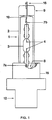
- FIG. 3 shows a second preferred embodiment of the high-pressure discharge lamp according to the invention.
- the construction of this lamp corresponds almost completely to the lamp shown in FIGS. 1 and 2.
- the same features are provided with a 30 reference number.
- the second end 39 of the outer bulb 32 (made of tempered glass) remote from the base is shaped into a dome.
- the pump tip 40 is now arranged in the center of the dome and thus lies in the lamp axis.
- the melting part 49 of the second power supply 48 is melted directly into the pump tip 40. With this manufacturing technique, care must be taken that the sealing section is sufficiently long, which is why the pump tip 40 must not be melted too short.
- molybdenum or tungsten can be used as the material for the melting part 49 in order to adapt to the coefficient of thermal expansion.
- an iron-nickel wire which may be coated with copper (F-wire). The longitudinal axis of the discharge vessel is again slightly shifted against the longitudinal axis of the outer bulb.
- any optical interference caused by the pump tip is avoided.
- this arrangement has a particularly favorable effect on the vibration behavior, since a mass concentration - as it represents a pinch seal - is avoided at a great distance from the "pivot point".
- Another advantage is that with this arrangement the appearance of the discharge lamp comes very close to the appearance of a conventional automotive halogen lamp.
- any anti-dazzle device is arranged separately in the headlight (e.g. in the form of an aperture).
- the outer bulb is provided on a part of its circumference with a shading layer, which acts with respect to a headlight as a dimming means for producing dipped beam. In order to avoid any shadowing from the second power supply, this layer is applied in particular where the second power supply is returned along the outer bulb.
Landscapes
- Vessels And Coating Films For Discharge Lamps (AREA)
- Non-Portable Lighting Devices Or Systems Thereof (AREA)
Applications Claiming Priority (2)
| Application Number | Priority Date | Filing Date | Title |
|---|---|---|---|
| DE3743627 | 1987-12-22 | ||
| DE19873743627 DE3743627A1 (de) | 1987-12-22 | 1987-12-22 | Hochdruckentladungslampe |
Publications (3)
| Publication Number | Publication Date |
|---|---|
| EP0321867A2 true EP0321867A2 (fr) | 1989-06-28 |
| EP0321867A3 EP0321867A3 (fr) | 1991-01-02 |
| EP0321867B1 EP0321867B1 (fr) | 1994-03-30 |
Family
ID=6343313
Family Applications (1)
| Application Number | Title | Priority Date | Filing Date |
|---|---|---|---|
| EP88121024A Expired - Lifetime EP0321867B1 (fr) | 1987-12-22 | 1988-12-15 | Lampe à décharge à haute pression |
Country Status (2)
| Country | Link |
|---|---|
| EP (1) | EP0321867B1 (fr) |
| DE (2) | DE3743627A1 (fr) |
Cited By (3)
| Publication number | Priority date | Publication date | Assignee | Title |
|---|---|---|---|---|
| EP0570068A1 (fr) * | 1992-05-11 | 1993-11-18 | Koninklijke Philips Electronics N.V. | Lampe à décharge à haute pression munie d'un culot |
| EP0571964A1 (fr) * | 1992-05-25 | 1993-12-01 | Patent-Treuhand-Gesellschaft für elektrische Glühlampen mbH | Lampe à décharge à haute pression à culot d'un côté |
| EP1139375A1 (fr) * | 2000-03-30 | 2001-10-04 | Heraeus Noblelight GmbH | Emetteur de rayonnement |
Families Citing this family (5)
| Publication number | Priority date | Publication date | Assignee | Title |
|---|---|---|---|---|
| GB2245417B (en) * | 1990-04-20 | 1994-06-08 | Koito Mfg Co Ltd | Discharge lamp device |
| US5220235A (en) * | 1990-04-20 | 1993-06-15 | Koito Manufacturing Co., Ltd. | Discharge lamp device |
| JP2761155B2 (ja) * | 1992-07-08 | 1998-06-04 | 株式会社小糸製作所 | 自動車用灯具の光源用放電ランプ装置 |
| JPH08162007A (ja) * | 1994-12-06 | 1996-06-21 | Koito Mfg Co Ltd | 放電ランプ装置 |
| DE102005007659A1 (de) * | 2005-02-19 | 2006-08-24 | Hella Kgaa Hueck & Co. | Brenner für eine Gasentladungslampe und Verfahren zur Herstellung des Brenners |
Family Cites Families (5)
| Publication number | Priority date | Publication date | Assignee | Title |
|---|---|---|---|---|
| US3110833A (en) * | 1961-02-21 | 1963-11-12 | Westinghouse Electric Corp | Multiple envelope high pressure mercury vapor discharge lamp |
| GB1305065A (fr) * | 1969-05-20 | 1973-01-31 | Patent Treuhand Ges Fuer Elektrische Gluehlampen Mbh | |
| NL7011321A (fr) * | 1970-07-31 | 1972-02-02 | ||
| US4254355A (en) * | 1978-09-11 | 1981-03-03 | General Electric Company | Ceramic arc tube mounting |
| DE3412489A1 (de) * | 1984-04-03 | 1985-10-03 | Patent-Treuhand-Gesellschaft für elektrische Glühlampen mbH, 8000 München | Einseitig gesockelte hochdruckentladungslampe |
-
1987
- 1987-12-22 DE DE19873743627 patent/DE3743627A1/de not_active Withdrawn
-
1988
- 1988-12-15 DE DE88121024T patent/DE3888808D1/de not_active Expired - Fee Related
- 1988-12-15 EP EP88121024A patent/EP0321867B1/fr not_active Expired - Lifetime
Cited By (6)
| Publication number | Priority date | Publication date | Assignee | Title |
|---|---|---|---|---|
| EP0570068A1 (fr) * | 1992-05-11 | 1993-11-18 | Koninklijke Philips Electronics N.V. | Lampe à décharge à haute pression munie d'un culot |
| US5736811A (en) * | 1992-05-11 | 1998-04-07 | U.S. Philips Corporation | Capped high-pressure discharge lamp |
| CN1053524C (zh) * | 1992-05-11 | 2000-06-14 | 皇家菲利浦电子有限公司 | 带帽高压放电灯 |
| EP0571964A1 (fr) * | 1992-05-25 | 1993-12-01 | Patent-Treuhand-Gesellschaft für elektrische Glühlampen mbH | Lampe à décharge à haute pression à culot d'un côté |
| EP1139375A1 (fr) * | 2000-03-30 | 2001-10-04 | Heraeus Noblelight GmbH | Emetteur de rayonnement |
| US6570307B2 (en) | 2000-03-30 | 2003-05-27 | Heraeus Noblelight Gmbh | Optical radiator with anti-extraction lock |
Also Published As
| Publication number | Publication date |
|---|---|
| EP0321867A3 (fr) | 1991-01-02 |
| EP0321867B1 (fr) | 1994-03-30 |
| DE3743627A1 (de) | 1989-07-06 |
| DE3888808D1 (de) | 1994-05-05 |
Similar Documents
| Publication | Publication Date | Title |
|---|---|---|
| DE19545530B4 (de) | Gasentladungslampenvorrichtung | |
| EP0536609A1 (fr) | Lampe à décharge à haute pression | |
| EP0887841B1 (fr) | Lampe à halogénure métallique avec enveloppe céramique | |
| DE102004027698A1 (de) | Kraftfahrzeugentladungslampe und Kraftfahrzeugscheinwerfer | |
| EP0321866B1 (fr) | Lampe à d'echarge à haute pression | |
| DE68911954T2 (de) | Elektrische Lampe. | |
| DE69603926T2 (de) | Beleuchtungseinheit, elektrodenlose niederdruckentladungslampe und entladungsgefäss zur verwendung in der beleuchtungseinheit | |
| EP0321867B1 (fr) | Lampe à décharge à haute pression | |
| EP0569824B1 (fr) | Lampe électrique | |
| EP0384240A2 (fr) | Lampe électrique à fixation du culot sans adhésif | |
| EP1294013B1 (fr) | Lampe à incandescence pour projecteur de véhicule automobile | |
| DE69830884T2 (de) | Elektrische glühlampe | |
| DE60028321T2 (de) | Elektrische glühlampe | |
| DE69608261T2 (de) | Niederdruckentladungslampe | |
| DE10236549A1 (de) | Elektrische Glühlampe | |
| EP1383159B1 (fr) | Lampe à reflecteur | |
| EP1138057A1 (fr) | Lampe a decharge haute pression | |
| EP1659617B1 (fr) | Source lumineuse | |
| EP2009668B1 (fr) | Lampe à décharge avec culot unique | |
| DE19538497C2 (de) | Verfahren zur Herstellung einer elektrischen Lampe | |
| EP0258829A2 (fr) | Lampe à décharge à haute pression et méthode pour la faire fonctionner | |
| EP2095399A2 (fr) | Ampoule à deux filaments | |
| EP0696724A1 (fr) | Aiguille avec éclairage et instrument avec une telle aiguille | |
| EP1465236A2 (fr) | Lampe à décharge | |
| DE102018201068B4 (de) | Glühlampe für fahrzeugscheinwerfer und herstellungsverfahren |
Legal Events
| Date | Code | Title | Description |
|---|---|---|---|
| PUAI | Public reference made under article 153(3) epc to a published international application that has entered the european phase |
Free format text: ORIGINAL CODE: 0009012 |
|
| AK | Designated contracting states |
Kind code of ref document: A2 Designated state(s): DE FR GB IT |
|
| RAP3 | Party data changed (applicant data changed or rights of an application transferred) |
Owner name: PATENT-TREUHAND-GESELLSCHAFT FUER ELEKTRISCHE GLUE |
|
| PUAL | Search report despatched |
Free format text: ORIGINAL CODE: 0009013 |
|
| AK | Designated contracting states |
Kind code of ref document: A3 Designated state(s): DE FR GB IT |
|
| RHK1 | Main classification (correction) |
Ipc: H01J 61/34 |
|
| 17P | Request for examination filed |
Effective date: 19901220 |
|
| 17Q | First examination report despatched |
Effective date: 19930622 |
|
| GRAA | (expected) grant |
Free format text: ORIGINAL CODE: 0009210 |
|
| AK | Designated contracting states |
Kind code of ref document: B1 Designated state(s): DE FR GB IT |
|
| REF | Corresponds to: |
Ref document number: 3888808 Country of ref document: DE Date of ref document: 19940505 |
|
| ITF | It: translation for a ep patent filed | ||
| GBT | Gb: translation of ep patent filed (gb section 77(6)(a)/1977) |
Effective date: 19940607 |
|
| ET | Fr: translation filed | ||
| PLBE | No opposition filed within time limit |
Free format text: ORIGINAL CODE: 0009261 |
|
| STAA | Information on the status of an ep patent application or granted ep patent |
Free format text: STATUS: NO OPPOSITION FILED WITHIN TIME LIMIT |
|
| 26N | No opposition filed | ||
| PGFP | Annual fee paid to national office [announced via postgrant information from national office to epo] |
Ref country code: GB Payment date: 19961118 Year of fee payment: 9 |
|
| PGFP | Annual fee paid to national office [announced via postgrant information from national office to epo] |
Ref country code: FR Payment date: 19961223 Year of fee payment: 9 |
|
| PG25 | Lapsed in a contracting state [announced via postgrant information from national office to epo] |
Ref country code: GB Free format text: LAPSE BECAUSE OF NON-PAYMENT OF DUE FEES Effective date: 19971215 |
|
| PG25 | Lapsed in a contracting state [announced via postgrant information from national office to epo] |
Ref country code: FR Free format text: THE PATENT HAS BEEN ANNULLED BY A DECISION OF A NATIONAL AUTHORITY Effective date: 19971231 |
|
| GBPC | Gb: european patent ceased through non-payment of renewal fee |
Effective date: 19971215 |
|
| REG | Reference to a national code |
Ref country code: FR Ref legal event code: ST |
|
| PGFP | Annual fee paid to national office [announced via postgrant information from national office to epo] |
Ref country code: DE Payment date: 19990219 Year of fee payment: 11 |
|
| PG25 | Lapsed in a contracting state [announced via postgrant information from national office to epo] |
Ref country code: DE Free format text: LAPSE BECAUSE OF NON-PAYMENT OF DUE FEES Effective date: 20001003 |
|
| PG25 | Lapsed in a contracting state [announced via postgrant information from national office to epo] |
Ref country code: IT Free format text: LAPSE BECAUSE OF NON-PAYMENT OF DUE FEES;WARNING: LAPSES OF ITALIAN PATENTS WITH EFFECTIVE DATE BEFORE 2007 MAY HAVE OCCURRED AT ANY TIME BEFORE 2007. THE CORRECT EFFECTIVE DATE MAY BE DIFFERENT FROM THE ONE RECORDED. Effective date: 20051215 |