EP0321885A1 - Tuyère pneumatique pour fausse torsion - Google Patents
Tuyère pneumatique pour fausse torsion Download PDFInfo
- Publication number
- EP0321885A1 EP0321885A1 EP88121141A EP88121141A EP0321885A1 EP 0321885 A1 EP0321885 A1 EP 0321885A1 EP 88121141 A EP88121141 A EP 88121141A EP 88121141 A EP88121141 A EP 88121141A EP 0321885 A1 EP0321885 A1 EP 0321885A1
- Authority
- EP
- European Patent Office
- Prior art keywords
- swirl
- air
- wall
- yarn
- fibers
- Prior art date
- Legal status (The legal status is an assumption and is not a legal conclusion. Google has not performed a legal analysis and makes no representation as to the accuracy of the status listed.)
- Withdrawn
Links
Images


Classifications
-
- D—TEXTILES; PAPER
- D01—NATURAL OR MAN-MADE THREADS OR FIBRES; SPINNING
- D01H—SPINNING OR TWISTING
- D01H1/00—Spinning or twisting machines in which the product is wound-up continuously
- D01H1/11—Spinning by false-twisting
- D01H1/115—Spinning by false-twisting using pneumatic means
Definitions
- the invention relates to a method according to the preamble of the first method claim and an air nozzle according to the preamble of the nozzle claim.
- a nozzle is from the German design No. 2722319, from European patent application no. 0131170, and also known from German Patent No. 3526514. From these documents it can be seen that such nozzles are used as so-called false twist nozzles in combination with a drafting system, in such a way that the drafting system delivers a sliver that divides the sliver into core fibers and edge fibers.
- the core fibers are twisted by the twist nozzle or, in the latter prior art, by the second twist nozzle, viewed in the running direction of the yarn, to an incorrectly twisted yarn core, which extends essentially from the twist-generating part of this nozzle up to the exit rollers of the drafting system.
- the edge fibers are by means of the air inflow channel or in the latter prior art first air nozzle, seen in the direction of the yarn, against the wrongly twisted core and wound around it.
- These twisted fibers are referred to as wrapping fibers, which wind around the yarn core (with essentially parallel fibers) which has been turned up again after the swirl part of the nozzle and thereby give the yarn the required strength.
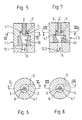
- FIG. 1 shows a swirl nozzle 1 with an inlet channel 2, which forms the inside diameter of a tube, the extension 3 of which protrudes with a length 1 into a cylindrical cavity 4 provided in the swirl nozzle 1. Furthermore, an air injection nozzle 5 merges with the outlet mouth 6 into the cylindrical cavity 4 such that, seen with a view of FIG. 1, the outlet mouth 7 of the inlet channel 2 is lower than the outlet mouth 6 of the air injection nozzle 5. This creates between the cylindrical inner wall 8 of the cavity 4 and the substantially cylindrical outer wall 9 of the tubular extension 3 an annular air duct for the air flow blown through the nozzle 5.
- the air injection nozzle 5 seen with a view of FIG. 1, is arranged on the one hand at an angle such that the axis of symmetry 10 of the injection nozzle 5 has an imaginary plane 11 which intersects the axis of symmetry 10 and, with a view of FIG. 1, perpendicular to the cutting surface and is to the longitudinal axis of this figure, forms an angle ⁇ and on the other hand, as shown in Fig. 2, opens tangentially into the cavity 4.
- the air stream that is blown in creates an air layer that runs around the cylindrical inner wall 8 and shifts in the direction of arrow A.
- the flow direction A creates a negative pressure in the inlet channel 2, according to the jet pump principle, which sucks air through the inlet channel 2 in the direction of the arrow A.
- the tube extension 3 protruding with the length 1 is missing, and the injection nozzles are mounted in such a way that the crank-like rotating yarn core interferes with the structure of the surrounding air layer, since the outlet opening is periodically covered by the rotating yarn crank, since the inflowing air is not forced to form a circumferential layer of air before it catches the yarn core.
- the rotating yarn core is wound by winding fibers which, even after the wrongly twisted yarn core has been untwisted, ensure that the core fibers lying essentially in the axial direction of the yarn are held together in order to thereby produce a usable yarn.
- Such a yarn is, as can be seen from the prior art mentioned, drawn off by a pair of draw-off rollers and fed to a winding device.
- a so-called helix formation in the yarn which continuously decreases towards the pair of draw-off rollers.
- an expanding cone 12 is provided after the cylindrical cavity 4 and has a predetermined length (not shown).
- FIGS. 3 to and 15 show variants of the swirl nozzle according to the invention, which is why the same or essentially the same elements are provided with the same reference numerals or with a decimal place.
- the dimensions of such elements shown can differ from FIG. To FIG.
- FIGS. 3 and 4 show an air nozzle 1 according to FIG. 1, but with an inlet duct 20 which is not essentially as in FIG. 1 a cylindrical, but has a shape at least similar to a Venturi tube.
- the advantage of this "venturi shape” lies in the smaller resistance for the amount of air to be sucked through and also offers the possibility of choosing the narrowest duct cross-section with constant air resistance, in order to create a balloon above the swirl nozzle as required, as seen in FIG. 3 , to prevent. Furthermore, the pipe extension has a mouth edge that is relatively narrow and thus leads to improved airflow and avoids turbulence.
- FIG. 5 shows a further variant in which a narrowing cone 30, viewed in direction A, is connected to the cylindrical cavity 4.1, by means of which the circumferential air layer blown in through the injection nozzle 5 and formed in the cavity 4.1 is narrowed, as a result of which the speed of rotation thereof circulating air layer is increased, with the advantage that the fibers captured by the air layer circulate at a correspondingly higher speed.
- Another advantage of this embodiment is that the narrowing of the air layer means that the fibers sucked in through the inlet channel 2 come into contact with the surrounding air layer more quickly.
- An expanding cone 12.1 is connected to the cone 30 and has the same function as the cone 12 of FIGS. 1 and 3.
- FIG. 7 shows a variant of FIG. 5, in that a constriction 40 is provided instead of the cone 30, which together with the cone 12.1 connected thereto has a shape similar to the Venturi nozzle principle.
- the advantage of the shape should be that of the Venturi nozzle, namely to improve the flow resistance of the air flow in the direction of arrow A and to provide a smoother transition from the narrowing cone 40 to the expanding cone 12.1.
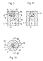
- FIG. 9 shows a further variant of the swirl nozzle of FIG. 1, in that the tubular extension 3 has an annular extension 50 (not shown in section in FIG. 11), which is provided with at least one helical groove 51.
- the annular extension 50 forms a compressed air space 52 with a height B in the cylindrical cavity 4.
- the two, for example, provided grooves 51 connect this compressed air space 52 with the part following the annular extension 50, in direction A. seen, the cylindrical cavity 4th
- the compressed air space 52 can be supplied with compressed air by means of a connecting bore 53.
- this compressed air flows through the helical grooves 51 into the lower part of the cylindrical cavity 4 and forms a circumferential layer of air through the helical shape of the grooves 51, which also moves in the conveying direction A.
- one or a plurality of helical grooves can be provided as required.
- the bore 53 does not necessarily have to open tangentially into the compressed air space 52, as is shown in FIGS. 1 to 8, since the rotation of the air layer is caused by the grooves 51.
- the compressed air space 52 can also be enlarged as desired in order to reduce the air speed therein and to improve the air distribution in the case of a plurality of grooves 51.
- FIG. 12 shows a variant of the swirl nozzle of FIG. 9, in that a conically shaped, annular extension 60 is provided instead of the cylindrical, annular extension 50.
- one or more helical grooves 61 are also provided, which have the same function as the grooves 51 in FIGS. 9 to 11.
- the extension 60 fits into a narrowing cone 62, which is followed by an expanding cone 63.
- the tube extension 3 is provided, for example, in an end plate 64 which is tightly connected to the nozzle body 65.
- the compressed air space 52 is supplied with compressed air by means of the bore 53, which passes through the helical grooves 61 into the narrowing cone 62 and forms a circumferential air layer therein, the speed of which increases with increasing constriction.
- the widening 60 seen in the direction of conveyance A, can be connected to a narrowing cone 66, the narrowing angle ⁇ of which can be determined empirically. A narrow mouth edge can also be achieved here.
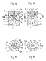
- tubular extension 3 additionally has a conical extension 70 which extends to the narrowest diameter of the cone 30.
- the extension 70 also has a narrow mouth edge. This creates an annular space with a conical cross-section.
- the widening cone 12.1 follows the cone 30
- the ratio length to diameter of the conical extension 70 or. of the cone 30 can be empirically optimized with regard to the desired acceleration of the air flow.
- an air injection nozzle 5.1 opens tangentially into the cylindrical cavity 4.1, the angle ⁇ (see FIG. 1) being essentially 0 degrees (not particularly marked in FIG. 14).
- the compressed air blown in through the air injection nozzle 5.1 is first circulated and secondly accelerated by the narrowing conical ring cross-section 71 in the direction of travel A, so that in the room immediately after the cone 30 or. the cone 70 a umlau air layer is created, which also moves in the conveying direction A.
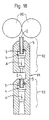
- FIGS. 16 and 17 show a possible application of the air nozzle shown in FIGS. 1 and 2, it being mentioned that all swirl nozzles shown in FIGS. 1 to 15 could be used in this example.
- FIGS. 16 and 17 corresponds to a modification according to the invention of the false twist nozzle shown in German Design No. 2722319 (St. d. T. mentioned at the beginning).
- the swirl nozzles shown in European patent application No. 0131170 (mentioned at the beginning of St. T.) could also be used.
- 16 shows a hint of an output roller pair 80 of a drafting system (not shown further) and a false twist nozzle body 81.
- the false twist nozzle body 81 viewed in the direction of conveyance A, comprises a feed channel 82, the inlet channel 2 with the tubular extension 3 and the cylindrical cavity 4, the air injection nozzle 5 and an expanding cone 12 connected to the cavity 4.
- the air layer circulating in the cavity 4 sets the yarn core 83 in rotation, as already described in the prior art mentioned, so that a false twist which extends against the pair of output rollers 80 occurs therein.
- the yarn experiences a helix formation and then the swirl of the yarn core 83.
- the yarn is then drawn off by a pair of draw-off rollers (not shown) and fed to a winding device (not shown).
- FIG. 18 shows a further possible application of the swirl nozzles shown with FIGS. 1 to 15.
- the example shows a false twist nozzle modified according to the invention from German laid-open specification DE 3526514 (St. d. T. mentioned at the beginning).
- This example shows a pair of output rollers 90 of a drafting system (not shown) and a false swirl nozzle body 91 with a first swirl nozzle area 92 and a second swirl nozzle area 93.
- the swirl nozzle of the region 93 serves to produce an incorrectly twisted core of yarn which extends in a manner known per se against the pair of output rollers 90, and the swirl nozzle of the region 92 serves in a manner known per se to wind the edge fibers around the incorrectly twisted yarn core.
- the examples shown are not limited to a single injection nozzle 5, but it goes without saying that a plurality of injection nozzles 5 which are uniform or distributed unevenly on the circumference can be used.
Landscapes
- Engineering & Computer Science (AREA)
- Mechanical Engineering (AREA)
- Textile Engineering (AREA)
- Spinning Or Twisting Of Yarns (AREA)
- Yarns And Mechanical Finishing Of Yarns Or Ropes (AREA)
Applications Claiming Priority (2)
| Application Number | Priority Date | Filing Date | Title |
|---|---|---|---|
| CH495087 | 1987-12-18 | ||
| CH4950/87 | 1987-12-18 |
Publications (1)
| Publication Number | Publication Date |
|---|---|
| EP0321885A1 true EP0321885A1 (fr) | 1989-06-28 |
Family
ID=4285351
Family Applications (1)
| Application Number | Title | Priority Date | Filing Date |
|---|---|---|---|
| EP88121141A Withdrawn EP0321885A1 (fr) | 1987-12-18 | 1988-12-16 | Tuyère pneumatique pour fausse torsion |
Country Status (3)
| Country | Link |
|---|---|
| US (1) | US4934133A (fr) |
| EP (1) | EP0321885A1 (fr) |
| JP (1) | JPH01162829A (fr) |
Cited By (9)
| Publication number | Priority date | Publication date | Assignee | Title |
|---|---|---|---|---|
| EP0415295A1 (fr) * | 1989-09-01 | 1991-03-06 | Maschinenfabrik Rieter Ag | Procédé de filage à fausse torsion et dispositif pour la mise en oeuvre de ce procédé |
| EP0418694A1 (fr) * | 1989-09-22 | 1991-03-27 | Maschinenfabrik Rieter Ag | Métier à filer à jet d'air avec une tuyère d'injection et une tuyère de torsion |
| EP0418693A1 (fr) * | 1989-09-21 | 1991-03-27 | Maschinenfabrik Rieter Ag | Tuyère d'un métier à filer à jet d'air |
| EP0489686A1 (fr) * | 1990-12-06 | 1992-06-10 | Maschinenfabrik Rieter Ag | Tuyère pour la production d'un mouvement hélicoidal dans un métier à filer à jets d'air |
| US5237810A (en) * | 1989-09-01 | 1993-08-24 | Maschinenfabrik Rieter Ag | Method and apparatus for false twist spinning |
| WO1994003662A1 (fr) * | 1992-07-31 | 1994-02-17 | Maschinenfabrik Rieter Ag | Dispositif de filage d'un ruban de fibres |
| EP0854214A3 (fr) * | 1997-01-16 | 1999-06-09 | Murata Kikai Kabushiki Kaisha | Appareil de filage |
| CN101798717A (zh) * | 2010-01-07 | 2010-08-11 | 杭州益邦氨纶有限公司 | 一种氨纶假捻器的校验装置 |
| CH712489A1 (de) * | 2016-05-26 | 2017-11-30 | Rieter Ag Maschf | Garnbildungselement für eine Vorspinnmaschine sowie damit ausgerüstete Vorspinnmaschine. |
Families Citing this family (5)
| Publication number | Priority date | Publication date | Assignee | Title |
|---|---|---|---|---|
| US5775079A (en) * | 1997-04-21 | 1998-07-07 | American Linc Corporation | Apparatus for imparting virtual twist to strand material and method of imparting same |
| GB9814476D0 (en) * | 1998-07-04 | 1998-09-02 | Fibreguide Ltd | Yarn treatment jet |
| AU2790600A (en) * | 1999-03-03 | 2000-09-21 | Heberlein Fibertechnology, Inc. | Method and device for processing filament yarn, and use of said device |
| DE50313024D1 (de) * | 2003-03-28 | 2010-10-07 | Oerlikon Heberlein Temco Wattw | Texturierdüse und verfahren zum texturieren von endlosgarn |
| DE602004016489D1 (de) * | 2004-07-28 | 2008-10-23 | Fare Spa | Vorrichtung und Verfahren zur Behandlung von synthetischen Garnen |
Citations (3)
| Publication number | Priority date | Publication date | Assignee | Title |
|---|---|---|---|---|
| US3490219A (en) * | 1966-12-29 | 1970-01-20 | Mitsubishi Rayon Co | Super high speed spinning method and apparatus for manufacturing jet bundle yarn |
| GB2174723A (en) * | 1985-05-07 | 1986-11-12 | Npk Textilno Mash | Air vortex nozzle for spinning yarn from staple fibres |
| WO1987003310A1 (fr) * | 1985-11-21 | 1987-06-04 | Schubert & Salzer Maschinenfabrik Aktiengesellscha | Procede et dispositif de renfilage d'un dispositif a filer pourvu d'un organe tordeur pneumatique |
Family Cites Families (13)
| Publication number | Priority date | Publication date | Assignee | Title |
|---|---|---|---|---|
| US3425359A (en) * | 1966-09-20 | 1969-02-04 | Japan National Railway | Apparatus for handling track installations |
| DE2722319B2 (de) * | 1977-01-10 | 1981-01-15 | Toyo Boseki K.K., Osaka (Japan) | Vorrichtung zum pneumatischen Falschdrallspinnen |
| JPS5837259B2 (ja) * | 1977-08-02 | 1983-08-15 | 株式会社東芝 | 光通信用ガラスファイバ−の製造方法 |
| JPS5625524A (en) * | 1979-08-07 | 1981-03-11 | Nissho Kosan Kk | Hinge structure of lid |
| US4242859A (en) * | 1980-01-21 | 1981-01-06 | Lawrence M. Keeler | Thread spinning apparatus |
| US4457130A (en) * | 1981-10-13 | 1984-07-03 | Murata Kikai Kabushiki Kaisha | Air spinning nozzle unit |
| US4437302A (en) * | 1982-01-20 | 1984-03-20 | Kabushiki Kaisha Toyoda Jidoshokki Seisakusho | False twisting air nozzle |
| IN161355B (fr) * | 1983-07-01 | 1987-11-14 | Rieter Ag Maschf | |
| DE3402460A1 (de) * | 1984-01-25 | 1985-08-01 | W. Schlafhorst & Co, 4050 Mönchengladbach | Drallgeber |
| US4569193A (en) * | 1984-06-04 | 1986-02-11 | Kabushiki Kaisha Toyoda Jidoshokki Seisakusho | Apparatus for producing a fasciated yarn |
| JPS6134234A (ja) * | 1984-07-26 | 1986-02-18 | Murata Mach Ltd | 空気式紡績装置 |
| JPS6288768A (ja) * | 1985-10-11 | 1987-04-23 | Hitachi Ltd | テ−プ送り制御方法及び装置 |
| DE3776347D1 (de) * | 1987-11-23 | 1992-03-05 | Toray Industries | Saugvorrichtung zum einfaedeln von faeden. |
-
1988
- 1988-11-25 JP JP63296420A patent/JPH01162829A/ja active Pending
- 1988-12-15 US US07/288,415 patent/US4934133A/en not_active Expired - Fee Related
- 1988-12-16 EP EP88121141A patent/EP0321885A1/fr not_active Withdrawn
Patent Citations (3)
| Publication number | Priority date | Publication date | Assignee | Title |
|---|---|---|---|---|
| US3490219A (en) * | 1966-12-29 | 1970-01-20 | Mitsubishi Rayon Co | Super high speed spinning method and apparatus for manufacturing jet bundle yarn |
| GB2174723A (en) * | 1985-05-07 | 1986-11-12 | Npk Textilno Mash | Air vortex nozzle for spinning yarn from staple fibres |
| WO1987003310A1 (fr) * | 1985-11-21 | 1987-06-04 | Schubert & Salzer Maschinenfabrik Aktiengesellscha | Procede et dispositif de renfilage d'un dispositif a filer pourvu d'un organe tordeur pneumatique |
Cited By (12)
| Publication number | Priority date | Publication date | Assignee | Title |
|---|---|---|---|---|
| EP0415295A1 (fr) * | 1989-09-01 | 1991-03-06 | Maschinenfabrik Rieter Ag | Procédé de filage à fausse torsion et dispositif pour la mise en oeuvre de ce procédé |
| US5237810A (en) * | 1989-09-01 | 1993-08-24 | Maschinenfabrik Rieter Ag | Method and apparatus for false twist spinning |
| EP0418693A1 (fr) * | 1989-09-21 | 1991-03-27 | Maschinenfabrik Rieter Ag | Tuyère d'un métier à filer à jet d'air |
| EP0418694A1 (fr) * | 1989-09-22 | 1991-03-27 | Maschinenfabrik Rieter Ag | Métier à filer à jet d'air avec une tuyère d'injection et une tuyère de torsion |
| EP0489686A1 (fr) * | 1990-12-06 | 1992-06-10 | Maschinenfabrik Rieter Ag | Tuyère pour la production d'un mouvement hélicoidal dans un métier à filer à jets d'air |
| US5230210A (en) * | 1990-12-06 | 1993-07-27 | Maschinenfabrick Rieter Ag | Nozzle for generating a twist in a jet spinning machine |
| CH682566A5 (de) * | 1990-12-06 | 1993-10-15 | Rieter Ag Maschf | Düse zur Drallerzeugung in einer Düsenspinnmaschine. |
| WO1994003662A1 (fr) * | 1992-07-31 | 1994-02-17 | Maschinenfabrik Rieter Ag | Dispositif de filage d'un ruban de fibres |
| EP0854214A3 (fr) * | 1997-01-16 | 1999-06-09 | Murata Kikai Kabushiki Kaisha | Appareil de filage |
| CN101798717A (zh) * | 2010-01-07 | 2010-08-11 | 杭州益邦氨纶有限公司 | 一种氨纶假捻器的校验装置 |
| CH712489A1 (de) * | 2016-05-26 | 2017-11-30 | Rieter Ag Maschf | Garnbildungselement für eine Vorspinnmaschine sowie damit ausgerüstete Vorspinnmaschine. |
| US10900144B2 (en) | 2016-05-26 | 2021-01-26 | Maschinenfabrik Rieter Ag | Roving-forming element for a roving machine as well as a roving machine equipped therewith |
Also Published As
| Publication number | Publication date |
|---|---|
| JPH01162829A (ja) | 1989-06-27 |
| US4934133A (en) | 1990-06-19 |
Similar Documents
| Publication | Publication Date | Title |
|---|---|---|
| EP1223236B1 (fr) | Dispositif pour la production d'un fil d'âme | |
| DE2660983C2 (de) | Verfahren zum pneumatischen Drallspinnen | |
| EP0321885A1 (fr) | Tuyère pneumatique pour fausse torsion | |
| DE3722771C1 (de) | Vorrichtung zum Zusammenfuehren eines textilen Faservlieses zu einem Faserband | |
| WO2002024993A2 (fr) | Dispositif de filage | |
| DE3639031C2 (fr) | ||
| DE3207136A1 (de) | Verfahren und vorrichtung zum herstellen eines fadens | |
| CH679491A5 (fr) | ||
| EP0121602A1 (fr) | Dispositif de fausse-torsion | |
| EP1217110A2 (fr) | Dispositif de filage | |
| EP1415027B1 (fr) | Dispositif pour produire un file | |
| EP0175862B1 (fr) | Procédé et dispositif pour la production de fil | |
| EP4259867B1 (fr) | Buse multifonctionnelle destinée à un métier à filer | |
| EP0305971A1 (fr) | Procédé et dispositif de filature par fausse torsion | |
| EP1279756A2 (fr) | Dispositif de filage pneumatique et procédé de filage pneumatique | |
| EP0712947B1 (fr) | Métier à filer à bout libre | |
| AT501520B1 (de) | Garnabzugseinrichtung für offenend-spinnvorrichtungen | |
| EP0205840B1 (fr) | Procédé et dispositif de filature par friction par fibres libérées | |
| CH659666A5 (de) | Einrichtung zum herstellen von buendelgarn. | |
| EP1587974B1 (fr) | Dispositif de fabrication d'un fil file | |
| EP3144419B1 (fr) | Adaptateur de plaques de canal et dispositif de filage à bout libre comprenant un adaptateur de plaques de canal | |
| EP0222101A1 (fr) | Procédé pour attacher un fil sur une machine de filature à friction | |
| EP0363649B1 (fr) | Dispositif de filature à friction | |
| CH678734A5 (fr) | ||
| DE3732967C2 (fr) |
Legal Events
| Date | Code | Title | Description |
|---|---|---|---|
| PUAI | Public reference made under article 153(3) epc to a published international application that has entered the european phase |
Free format text: ORIGINAL CODE: 0009012 |
|
| AK | Designated contracting states |
Kind code of ref document: A1 Designated state(s): AT CH DE ES FR GB IT LI |
|
| 17P | Request for examination filed |
Effective date: 19890817 |
|
| 17Q | First examination report despatched |
Effective date: 19910129 |
|
| STAA | Information on the status of an ep patent application or granted ep patent |
Free format text: STATUS: THE APPLICATION IS DEEMED TO BE WITHDRAWN |
|
| 18D | Application deemed to be withdrawn |
Effective date: 19941201 |