EP0322570A1 - Chapeau pour cheminée - Google Patents
Chapeau pour cheminée Download PDFInfo
- Publication number
- EP0322570A1 EP0322570A1 EP88119738A EP88119738A EP0322570A1 EP 0322570 A1 EP0322570 A1 EP 0322570A1 EP 88119738 A EP88119738 A EP 88119738A EP 88119738 A EP88119738 A EP 88119738A EP 0322570 A1 EP0322570 A1 EP 0322570A1
- Authority
- EP
- European Patent Office
- Prior art keywords
- hollow cross
- chimney
- sections
- attachment according
- cone
- Prior art date
- Legal status (The legal status is an assumption and is not a legal conclusion. Google has not performed a legal analysis and makes no representation as to the accuracy of the status listed.)
- Withdrawn
Links
Images
Classifications
-
- F—MECHANICAL ENGINEERING; LIGHTING; HEATING; WEAPONS; BLASTING
- F23—COMBUSTION APPARATUS; COMBUSTION PROCESSES
- F23L—SUPPLYING AIR OR NON-COMBUSTIBLE LIQUIDS OR GASES TO COMBUSTION APPARATUS IN GENERAL ; VALVES OR DAMPERS SPECIALLY ADAPTED FOR CONTROLLING AIR SUPPLY OR DRAUGHT IN COMBUSTION APPARATUS; INDUCING DRAUGHT IN COMBUSTION APPARATUS; TOPS FOR CHIMNEYS OR VENTILATING SHAFTS; TERMINALS FOR FLUES
- F23L17/00—Inducing draught; Tops for chimneys or ventilating shafts; Terminals for flues
- F23L17/02—Tops for chimneys or ventilating shafts; Terminals for flues
Definitions
- the invention relates to an attachment for fireplaces, the fireplaces being lined against sooting.
- the object of the invention is to improve the chimney draft and to achieve a certain catalyst effect, ie it is intended to promote sooting through the attachment, in order to reduce the emission of pollutants from the chimney.
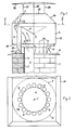
- an attachment 2 is provided on a chimney 1.
- This attachment 2 engages with a kind of socket 3 in the chimney cross section 4, which has a sootproof lining 5.
- a baffle cone 6 is provided over the free hollow cross section of the chimney 1 or the plug-in sleeve 3 and has a drain hole 7.
- the baffle cone 6 is surrounded by a plurality of pipe pieces 8 which are spaced 9 from one another in the circumferential direction.
- the lower ends 10 of the pipe sections 8 are cut off at an angle and are supported on a flange 11 of the push-in sleeve 3.
- the flange 11 is roof-like and projects beyond the outer dimensions of the chimney 1.
- the pipe sections 8 pass through an annular bottom 12, which has a conical shape. Since the pipe pieces 8 firmly are connected to the floor 12, they can also carry the impact cone 6, which could also be arranged to be adjustable in height.
- the annular bottom 12 continues upwards into a cylindrical shell 13 which merges into a conical part 14.
- This conical part 14 forms an outflow cross section 15 which is larger than the cross section of the push-in sleeve 3.
- a cover 16 is provided which sits on three supports 17, 18, 19 of the conical part 14.
- the operation of the article 2 according to the invention is easy to explain.
- the flue gas flowing out of the chimney 1 is deflected outwards by the impact cone 6, as can be seen from the arrows 20. They flow through the spaces 9 between the pipe sections 8, which are cooled by fresh air - cf. arrows 21, 22 - are flowed through, so that the flue gases cool down and the dew point is reached.
- the resulting condensate enters the baffle cone 6 and from there through the drip opening 7 into a lower, not shown, container of the fireplace.
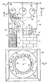
- a modified attachment 2 is provided on a chimney 1.
- This article 2 corresponds in the lower part to article 2 of Fig. 1, i.e. it engages with a kind of socket 3 in the chimney cross section 4, which has a sootproof lining 5.
- a baffle cone 6 is provided over the free hollow cross section of the chimney 1 or the plug-in sleeve 3 and has a drain hole 7.
- the baffle cone 6 is surrounded by a plurality of pipe pieces 8 which are spaced 9 from one another in the circumferential direction.
- the lower ends 10 of the pipe sections 8 are cut off at an angle and are supported on a flange 11 of the push-in sleeve 3.
- the flange 11 is roof-like and projects beyond the outer dimensions of the chimney 1.
- the pipe sections 8 pass through an annular bottom 12, which has a conical shape. Since the pipe sections 8 are firmly connected to the base 12, they are also able to carry the impact cone 6, which could also be arranged to be adjustable in height.
- the annular bottom 12 continues upwards into a cylindrical jacket 13 which projects significantly beyond the hollow cross sections 8 and is closed with a cover 30 which has a bevel 31 so that the cover 30 has a roof-like effect for the cylinder 13.
- the cover 30 is hinged to the jacket 13 so that it can snap up around the joint 32 in the event of a deflagration in the chimney 1.
- a stop is indicated at 33, which comes to bear against the jacket 13 when the cover 30 is raised, so that the cover 30 only has an angle of for example, can take 45 ° relative to the upper edge of the jacket 13. It goes without saying that such a secured cover 30 automatically returns to its original position.
- flue gas outlet openings 34 are provided in the jacket, which are simultaneously distributed over the circumference of the jacket 13. Their total cross-section is larger than the chimney cross-section, so that no jam can occur. The arrangement and design of the flue gas outlet openings 34 have already been discussed.
- the impact cone 6 is hinged like the cover 30 at 35 and is also equipped with a stop (only indicated by dashed lines) 36, which comes to rest on the edge of at least one hollow cross section 8 when the impact cone 6 rises, as shown in FIG. 2 reveals.
- a stop (only indicated by dashed lines) 36, which comes to rest on the edge of at least one hollow cross section 8 when the impact cone 6 rises, as shown in FIG. 2 reveals.
- a sword-like approach is indicated, which serves the impact cone 6 as a support.
- This stop 37 is not required if the impact cone 6 projects radially beyond the hollow cross sections 8, as is indicated by dashed lines 38 in FIGS. 3 and 4.
- the operation of the essay 2 according to the invention is easy to explain.
- the flue gas flowing out of the chimney 1 is deflected outwards by the impact cone 6, as can be seen from the arrows 20. They flow through the spaces 9 between the pipe pieces 8, which are cooled by fresh air - cf. for this purpose, the arrows 21, 22 also in FIG. 4 - are flowed through, so that the flue gases are cooled down and the dew point is reached.
- the resulting condensate enters the baffle cone 6 and from there through the Ab drip opening 7 in a lower, not shown container of the fireplace 1; condensate can also drip onto the conical bottom 12 and flow into the chimney 1.
Landscapes
- Engineering & Computer Science (AREA)
- Chemical & Material Sciences (AREA)
- Combustion & Propulsion (AREA)
- Mechanical Engineering (AREA)
- General Engineering & Computer Science (AREA)
- Chimneys And Flues (AREA)
- Air-Flow Control Members (AREA)
Applications Claiming Priority (4)
| Application Number | Priority Date | Filing Date | Title |
|---|---|---|---|
| DE3740621 | 1987-12-01 | ||
| DE19873740621 DE3740621A1 (de) | 1987-12-01 | 1987-12-01 | Aufsatz fuer kamine |
| DE19883818937 DE3818937A1 (de) | 1987-12-01 | 1988-06-03 | Aufsatz fuer kamine |
| DE3818937 | 1988-06-03 |
Publications (1)
| Publication Number | Publication Date |
|---|---|
| EP0322570A1 true EP0322570A1 (fr) | 1989-07-05 |
Family
ID=25862307
Family Applications (1)
| Application Number | Title | Priority Date | Filing Date |
|---|---|---|---|
| EP88119738A Withdrawn EP0322570A1 (fr) | 1987-12-01 | 1988-11-28 | Chapeau pour cheminée |
Country Status (2)
| Country | Link |
|---|---|
| EP (1) | EP0322570A1 (fr) |
| DE (1) | DE3818937A1 (fr) |
Cited By (5)
| Publication number | Priority date | Publication date | Assignee | Title |
|---|---|---|---|---|
| WO2009042005A3 (fr) * | 2007-09-27 | 2010-03-18 | Arnold John G Jr | Dispositif de chapeau et de filtre de conduit de cheminée pour un appareil chauffé au gaz |
| USD677375S1 (en) | 2011-09-20 | 2013-03-05 | European Copper, Llc | Direct vent exhaust termination |
| USD677374S1 (en) | 2011-09-20 | 2013-03-05 | European Copper, Llc | B vent exhaust termination |
| WO2015131859A1 (fr) * | 2014-03-03 | 2015-09-11 | Ondrisek Pavel | Optimiseur de tirage de cheminée |
| US9863634B1 (en) | 2007-09-27 | 2018-01-09 | European Copper, Llc | Exhaust flue cap and filter device for a gas fired appliance |
Citations (4)
| Publication number | Priority date | Publication date | Assignee | Title |
|---|---|---|---|---|
| FR525230A (fr) * | 1920-09-29 | 1921-09-17 | Josqui Et Cie | Régulateur de tirage |
| US1545618A (en) * | 1923-04-19 | 1925-07-14 | Sundahl Clarence | Ventilator |
| GB402896A (en) * | 1932-08-23 | 1933-12-14 | Edmund William Mayner | A new or improved chimney-cowl |
| US2515467A (en) * | 1949-03-18 | 1950-07-18 | Orwin W Peterson | Ventilator for chimney stacks and the like |
-
1988
- 1988-06-03 DE DE19883818937 patent/DE3818937A1/de not_active Withdrawn
- 1988-11-28 EP EP88119738A patent/EP0322570A1/fr not_active Withdrawn
Patent Citations (4)
| Publication number | Priority date | Publication date | Assignee | Title |
|---|---|---|---|---|
| FR525230A (fr) * | 1920-09-29 | 1921-09-17 | Josqui Et Cie | Régulateur de tirage |
| US1545618A (en) * | 1923-04-19 | 1925-07-14 | Sundahl Clarence | Ventilator |
| GB402896A (en) * | 1932-08-23 | 1933-12-14 | Edmund William Mayner | A new or improved chimney-cowl |
| US2515467A (en) * | 1949-03-18 | 1950-07-18 | Orwin W Peterson | Ventilator for chimney stacks and the like |
Cited By (6)
| Publication number | Priority date | Publication date | Assignee | Title |
|---|---|---|---|---|
| WO2009042005A3 (fr) * | 2007-09-27 | 2010-03-18 | Arnold John G Jr | Dispositif de chapeau et de filtre de conduit de cheminée pour un appareil chauffé au gaz |
| US8083574B2 (en) | 2007-09-27 | 2011-12-27 | John G. Arnold, Jr. | Exhaust flue cap and filter device for a gas fired appliance |
| US9863634B1 (en) | 2007-09-27 | 2018-01-09 | European Copper, Llc | Exhaust flue cap and filter device for a gas fired appliance |
| USD677375S1 (en) | 2011-09-20 | 2013-03-05 | European Copper, Llc | Direct vent exhaust termination |
| USD677374S1 (en) | 2011-09-20 | 2013-03-05 | European Copper, Llc | B vent exhaust termination |
| WO2015131859A1 (fr) * | 2014-03-03 | 2015-09-11 | Ondrisek Pavel | Optimiseur de tirage de cheminée |
Also Published As
| Publication number | Publication date |
|---|---|
| DE3818937A1 (de) | 1989-12-14 |
Similar Documents
| Publication | Publication Date | Title |
|---|---|---|
| EP0322570A1 (fr) | Chapeau pour cheminée | |
| DE3151327A1 (de) | Kamin zum abzug von rauchgasen | |
| DE102007004879A1 (de) | Abzugsschacht | |
| DE69414061T2 (de) | Gasabfuhreinrichtung | |
| DE1753282B1 (de) | Entlueftungsaufsatz fuer Schornsteine,Entlueftungsa.lagen od.dgl. | |
| EP3736490B1 (fr) | Dispositif comprenant un corps creux ouvert vers le haut et un couvercle pouvant être enlevé | |
| EP0122413B1 (fr) | Abat-vent | |
| DE3740621A1 (de) | Aufsatz fuer kamine | |
| EP0293332B1 (fr) | Chapeau de cheminée | |
| DE2924963C2 (de) | Kaminkopf für Luft-Abgas-Schornsteine | |
| DE8136736U1 (de) | Mauerkasten | |
| EP3438527A1 (fr) | Corps creux ouvert vers le haut pourvu d'un couvercle | |
| DE19815493C2 (de) | Schornsteinkopf | |
| DE2200418A1 (de) | Gasbrenner mit seitlichen OEffnungen und mit einer Ablenkeinrichtung,welche die Flammen nach oben ablenkt | |
| DE3244502C2 (de) | Mauerkasten | |
| DE3314939A1 (de) | Kaminabdeckung | |
| DE4302229A1 (de) | Rauchgasabströmkopf bzw. Vorrichtung als äußerer Abschluß eines Rauchgasrohrs sowie Zuschnitt für einen Rauchgasabströmkopf | |
| DE3317366A1 (de) | Kaminaufsatz | |
| DE3222387A1 (de) | Abgaskanal, insbesondere mit eingebautem schalldaempfer aus mit mineralwolle gefuellten kulissen, sowie regenschutzvorrichtung hierfuer | |
| DE8312172U1 (de) | Kaminabdeckung | |
| DE7930514U1 (de) | Deflektorhaube fuer den abschluss von lueftungsschaechten | |
| CH678549A5 (en) | Chimney extension to control smoke discharge - comprises circular annular bodies with domed surfaces detachably secured together by distance pieces | |
| AT525343A4 (de) | Grablicht | |
| DE29519286U1 (de) | Kaminkopf für einen Stahlkamin | |
| DE1260669B (de) | Schornsteinaufsatz |
Legal Events
| Date | Code | Title | Description |
|---|---|---|---|
| PUAI | Public reference made under article 153(3) epc to a published international application that has entered the european phase |
Free format text: ORIGINAL CODE: 0009012 |
|
| AK | Designated contracting states |
Kind code of ref document: A1 Designated state(s): AT BE CH DE ES FR GB GR IT LI LU NL SE |
|
| STAA | Information on the status of an ep patent application or granted ep patent |
Free format text: STATUS: THE APPLICATION IS DEEMED TO BE WITHDRAWN |
|
| 18D | Application deemed to be withdrawn |
Effective date: 19900106 |