EP0322733A1 - Wärmeleitungsvorrichtung - Google Patents
Wärmeleitungsvorrichtung Download PDFInfo
- Publication number
- EP0322733A1 EP0322733A1 EP88121382A EP88121382A EP0322733A1 EP 0322733 A1 EP0322733 A1 EP 0322733A1 EP 88121382 A EP88121382 A EP 88121382A EP 88121382 A EP88121382 A EP 88121382A EP 0322733 A1 EP0322733 A1 EP 0322733A1
- Authority
- EP
- European Patent Office
- Prior art keywords
- heat
- heat pipe
- pipe
- drive pump
- operating liquid
- Prior art date
- Legal status (The legal status is an assumption and is not a legal conclusion. Google has not performed a legal analysis and makes no representation as to the accuracy of the status listed.)
- Granted
Links
Images


Classifications
-
- F—MECHANICAL ENGINEERING; LIGHTING; HEATING; WEAPONS; BLASTING
- F28—HEAT EXCHANGE IN GENERAL
- F28D—HEAT-EXCHANGE APPARATUS, NOT PROVIDED FOR IN ANOTHER SUBCLASS, IN WHICH THE HEAT-EXCHANGE MEDIA DO NOT COME INTO DIRECT CONTACT
- F28D15/00—Heat-exchange apparatus with the intermediate heat-transfer medium in closed tubes passing into or through the conduit walls ; Heat-exchange apparatus employing intermediate heat-transfer medium or bodies
- F28D15/02—Heat-exchange apparatus with the intermediate heat-transfer medium in closed tubes passing into or through the conduit walls ; Heat-exchange apparatus employing intermediate heat-transfer medium or bodies in which the medium condenses and evaporates, e.g. heat pipes
- F28D15/06—Control arrangements therefor
Definitions
- the present invention relates to a heat pipe, and more particularly, to a heat pipe which can be used in a case where a conventional heat pipe cannot sufficiently accomplish the task in such a case where a great amount of heat is intended to be conducted, a case of a top heat mode, and a case where heat conduction is performed over a long distance.
- a case can be exemplified by that heat accumulated by a solar concentrator mounted on a roof of a house is conducted to an underground heat accumulation tank.
- a heat pipe is widely used in various industrial fields since it can conduct heat several hundred times that conducted by a copper rod of the same form.
- a heat pipe vaporizes inside operating liquid in a high temperature portion thereof, the thus-formed steam is by the steam pressure difference transmitted to a low temperature portion thereof at which the steam is condensed so that heat corresponding to heat of vaporization is quickly transmitted from the high temperature portion to the low temperature portion.
- the thus-condensed liquid is returned to the high temperature portion by a capillary force generated in a portion called "wick" on the inner wall of the heat pipe.
- An object of the present invention is to provide a heat conducting device capable of satisfactorily overcoming the above-described problems and with which the amount of the heat transmission can be controlled.
- a heat conducting device comprises a heat drive pump operated by using growth and contraction of steam bubbles due to heat, whereby the temperature of operating liquid condensed in a cooling portion of a heat pipe is made lower than that of the cooling portion of the heat pipe, and then the operating liquid is arranged to be returned to a heating portion of the heat pipe, as a result of which the heat pipe can be continuously operated.
- Another aspect of the present invention is a heat conducting device in which a heat source for the heat drive pump is arranged to be the heating portion of the heat pipe, and a cooler is disposed in a flow passage which connects an outlet of the cooling portion and an inlet of the heat drive pump for the purpose of making the temperature of the operating liquid condensed in the cooling portion of the heat pipe lower than that of the cooling portion.
- a still further aspect of the present invention is a heat conducting device in which a flow distribution valve for dividing the flow and a conducting pipe for introducing the thus-divided operating liquid into an inlet of a radiator are provided at an outlet of the heat drive pump.
- a heat conducting device further comprising a cyclic flow passage including the heat pipe and a cyclic flow passage including the heat drive pump, wherein the two flow passages are connected to each other by a pressure conducting part such as diaphragm.
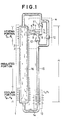
- Fig. 1 illustrates an embodiment of the present invention.
- the portion surrounded by a short dashed line 1 serves as a conventional heat pipe which is designed in such a manner that an wick 3 of a porous structure or a meshed structure for the purpose of effectively wetting operating liquid is put through the entire inner surface of a container 2 made of a thin and thermal-conductive material pipe such as copper.
- the portion surrounded by a short dashed line 4 serves as a heat drive pump which includes a pump heating portion 5 made of a thermal-conductive material, and a conical liquid receptacle portion 6 therein.
- the pump heating portion 5 is, integrally or in a similar manner, secured to the heat pipe heating portion of the container 2 for the purpose of establishing the same temperature between the pump heating portion 5 and the heat pipe heating portion of the container 2.
- a gas-liquid converting chamber 7 comprises a thin pipe made of a stainless steel or the like having a poor thermal conductivity for the purpose of preventing heat transmission from the pump heating portion 5 to the liquid in the gas-liquid converting chamber 7.
- a condensing pipe 8 is secured in the converting chamber 7 and a plurality of capillary force generating fins 9 are disposed at the front end of this condensing pipe 8.
- the converting chamber 7 is connected to a suction side stopper valve 10 and a delivery side stopper valve 11 with conducting pipes respectively.
- An water hammer prevention stopper valve 12 is disposed in a conducting pipe which bypasses the main heat drive pump body.
- the portion surrounded by a dashed line 13 serves as a return cooler which acts to further cool the operating liquid which has been condensed and gathered in a heat pipe cooling portion.
- the front end of the delivery stopper valve of the heat drive pump and the front end of the heat pipe heating portion, the lower end of the heat pipe cooling portion and the return cooler, and the return cooler and the heat drive pump suction side stopper valve are respectively connected by the conducting pipe 15. As a result, a closed circuit is formed so that the operating liquid 14 is circulated.
- the heat pipe according to the present invention is disposed vertically with respect to the ground and the height thereof is H.
- the top end of this heat pipe serves as a heating portion so that heat is transmitted to the lower end of the same.
- All of the conducting pipes, heat drive pump 4, wick 3 of the container 2 are filled with the operating liquid, while a space 16 other than the above-described members in the heat pipe is filled with the steam from the operating liquid.
- the steam bubbles are completely brought into an contraction process.
- the operating liquid which has been sufficiently cooled is taken in through the conducting pipe by closing the delivery side stopper valve 11 and by opening the suction side stopper valve 10. That is, the operating liquid accumulated at the cooling portion of the heat pipe is cooled by the return cooler, and is then supplied to the heat drive pump.
- the water hammer prevention stopper valve 12 is provided for the purpose of relief a high pressure generated by the inertia of the liquid in the conducting pipe when the suction side stopper valve 10 of the heat drive pump is closed and when the delivery side stopper valve is closed.
- the pressure difference P2 - P4 P2 - (P3 + b) serves as the motive power to raising the operating liquid from the cooling portion up to the liquid-gas converting chamber against pressure ⁇ H due to a head H and the fluid pressure P D due to the conducting pipe or the stopper valve.
- the position for the return cooler 13 it may be arranged in a conducting pipe from the outlet of the heat pipe cooling portion and the inlet of the heat drive pump or the gas-liquid chamber 7 may be cooled by proper means.
- the position for the return cooler at which the device according to the present invention can exhibit its extreme performance is the position in the vicinity of the outlet of the heat pipe cooling portion.
- Fig. 2 illustrates a modification of the present invention.
- the heat pipe 1, heat drive pump 4, return cooler 13 and the conducting pipe 15 for connecting the former members are similarly provided to the embodiment shown in Fig. 1.
- a flow distribution valve 17 is disposed in the conducting pipe which connects the heat drive pump 4 and the heating portion of the heat pipe 1.
- the thus-divided conducting pipe 18 through which the operating liquid supplied from the heat drive pump is connected to the inlet of the return cooler.
- the flow distribution valve 17 includes a rotary valve 21, as a result of which the operating liquid discharged by the heat drive pump is jetted through an aperture 22 formed at the central portion of this flow distribution valve 17, the thus-jetted operating liquid being then divided into a right flow and a left flow.
- a rotary valve 21 is rotated by moving a lever 20 so that the engagement areas between the rotary valve 21 and the right and left outlet ports are changed.
- the flow of the operating liquid supplied from the heat drive pump to the heat pipe heating portion can be changed from 0% to 100%, that is, the heat conducting performance of the heat pipe can be changed.
- the operating fluid which has been divided and introduced into the conducting pipe 18 is, at the inlet of the return cooler, mixed with the operating liquid from the heat pipe so that the thus-mixed operating fluid is cooled down by the return cooler and then returns to the heat drive pump via the conducting pipe 15.
- the system in which a divided flow passage is individually provided for the purpose of controlling the flow which passes through the main flow passage including the heat pipe can exhibit the following advantages as: when the temperature of the heat pipe heating portion is constant, the amount of jetted operating liquid from the heat drive pump becomes constant. Therefore, the amount of jetted operating liquid is free from the affection of the amount of heat transfer through the heat pipe. As a result, the amount of heat transfer can be easily controlled.
- the heat drive pump can be continuously operated even if the amount of heat transfer through the heat pipe is zero, that is, even if no operating liquid is supplied to the heat pipe.
- the heat drive pump can always supply the operating liquid to the heat pipe.
- Fig. 3 illustrates another modification of the present invention.
- the device according to this modification is arranged in such a manner that liquid which passes through the heat drive pump and liquid which passes through the heat pipe are separated by a diaphragm 24 so that different types of liquid can be individually used.
- the effect of the return cooler can be improved so that a greater steam pressure difference can be generated between the diaphragm 25 and the heat pipe cooling portion.
- Heat generated in the heat drive pump 4 radiates outside by a pump radiator 26 included in the heat drive pump 4 so that only the capacity change due to the growth and contraction of the steam bubbles in the receptance portion 6 is introduced from the conducting pipe 27 into the pump flow distribution valve 28. Therefore, division of the capacity change for an accumulator 29 and a diaphragm pump 25 can be performed simply by rotating a lever 30. As a result, the amount of discharge from the diaphragm pump 25 can be changed, and thereby the heat transferring performance of the heat pipe can be changed.
- the inlet and outlet of the diaphragm pump is respectively provided with a diaphragm suction stopper valve 31 and a diaphragm delivery stopper valve 32 so that a pumping operation can be achieved.
- the operating liquid can comprise the operating liquid used in the heat pipe.
- the heat source of the heat drive pump depends without exception upon the heat pipe heating portion in this embodiment, other heat source may be employed if possible.
- the wick is laid through the entire inner surface of the heat pipe, the wick may be arranged to be divided into the heating portion and the cooling portion.
- the heat pipe is used in a top heat mode without exception, it may be used in a horizontal mode or a reverse mode with no problem. In such cases, the amount of heat transfer can be increased.
- the performance of the heat pipe can be significantly improved. That is, in the conventional heat pipes, the return of the operating liquid to the heating portion completely depends upon the capillary force of the wick. This arises problems when a heat source disposed at a rather higher position is used or when the heat pipe is used to transfer heat over a long distance.
- the operating liquid can be returned by the heat drive pump, the operating liquid can be transferred to higher positions or over a long distance. As a result, the above-described problems can be overcome.
- the conventional device utilizes electricity or a centrifugal force for the purpose of returning the operating liquid
- the heat can be returned by utilizing the heat in the heating portion in the present invention. Consequently, a simple structured and reliable device can be provided.
Landscapes
- Engineering & Computer Science (AREA)
- Life Sciences & Earth Sciences (AREA)
- Sustainable Development (AREA)
- Physics & Mathematics (AREA)
- Thermal Sciences (AREA)
- Mechanical Engineering (AREA)
- General Engineering & Computer Science (AREA)
- Electromagnetic Pumps, Or The Like (AREA)
- Central Heating Systems (AREA)
Applications Claiming Priority (2)
| Application Number | Priority Date | Filing Date | Title |
|---|---|---|---|
| JP62324818A JP2657809B2 (ja) | 1987-12-22 | 1987-12-22 | 熱伝達装置 |
| JP324818/87 | 1987-12-22 |
Publications (2)
| Publication Number | Publication Date |
|---|---|
| EP0322733A1 true EP0322733A1 (de) | 1989-07-05 |
| EP0322733B1 EP0322733B1 (de) | 1991-08-28 |
Family
ID=18170013
Family Applications (1)
| Application Number | Title | Priority Date | Filing Date |
|---|---|---|---|
| EP88121382A Expired EP0322733B1 (de) | 1987-12-22 | 1988-12-21 | Wärmeleitungsvorrichtung |
Country Status (4)
| Country | Link |
|---|---|
| US (1) | US4986348A (de) |
| EP (1) | EP0322733B1 (de) |
| JP (1) | JP2657809B2 (de) |
| DE (1) | DE3864507D1 (de) |
Cited By (3)
| Publication number | Priority date | Publication date | Assignee | Title |
|---|---|---|---|---|
| CN109139433A (zh) * | 2018-08-17 | 2019-01-04 | 北京理工大学 | 可利用连续热源的气泡驱动无阀微泵 |
| CN109690221A (zh) * | 2016-09-09 | 2019-04-26 | 株式会社电装 | 设备温度调节装置 |
| CN110892225A (zh) * | 2017-09-13 | 2020-03-17 | 株式会社电装 | 设备温度调节装置 |
Families Citing this family (17)
| Publication number | Priority date | Publication date | Assignee | Title |
|---|---|---|---|---|
| US5127471A (en) * | 1991-07-26 | 1992-07-07 | Weislogel Mark M | Pulse thermal energy transport/storage system |
| JPH05248777A (ja) * | 1992-03-05 | 1993-09-24 | Agency Of Ind Science & Technol | トップヒート用分離型ヒートパイプ |
| US5911272A (en) * | 1996-09-11 | 1999-06-15 | Hughes Electronics Corporation | Mechanically pumped heat pipe |
| US6047766A (en) * | 1998-08-03 | 2000-04-11 | Hewlett-Packard Company | Multi-mode heat transfer using a thermal heat pipe valve |
| US6789611B1 (en) * | 2000-01-04 | 2004-09-14 | Jia Hao Li | Bubble cycling heat exchanger |
| US6684941B1 (en) * | 2002-06-04 | 2004-02-03 | Yiding Cao | Reciprocating-mechanism driven heat loop |
| JP4214881B2 (ja) * | 2003-01-21 | 2009-01-28 | 三菱電機株式会社 | 気泡ポンプ型熱輸送機器 |
| US6983790B2 (en) * | 2003-03-27 | 2006-01-10 | Mitsubishi Denki Kabushiki Kaisha | Heat transport device, semiconductor apparatus using the heat transport device and extra-atmospheric mobile unit using the heat transport device |
| US20040244963A1 (en) * | 2003-06-05 | 2004-12-09 | Nikon Corporation | Heat pipe with temperature control |
| CN2694210Y (zh) * | 2004-03-18 | 2005-04-20 | 鸿富锦精密工业(深圳)有限公司 | 相变化散热装置 |
| JP4653082B2 (ja) * | 2004-03-30 | 2011-03-16 | 謙治 岡安 | 携帯式熱伝達装置 |
| US7288864B2 (en) * | 2004-03-31 | 2007-10-30 | Nikon Corporation | System and method for cooling motors of a lithographic tool |
| CN100489433C (zh) * | 2004-12-17 | 2009-05-20 | 尹学军 | 自然冷能的热管装置及其应用 |
| JP4381998B2 (ja) * | 2005-02-24 | 2009-12-09 | 株式会社日立製作所 | 液冷システム |
| RU2361168C1 (ru) * | 2007-10-29 | 2009-07-10 | Сергей Анатольевич Ермаков | Тепловая труба |
| FR2979982B1 (fr) * | 2011-09-14 | 2016-09-09 | Euro Heat Pipes | Dispositif de transport de chaleur a pompage capillaire |
| FR2979981B1 (fr) | 2011-09-14 | 2016-09-09 | Euro Heat Pipes | Dispositif de transport de chaleur a pompage capillaire |
Citations (2)
| Publication number | Priority date | Publication date | Assignee | Title |
|---|---|---|---|---|
| GB1293279A (en) * | 1969-11-15 | 1972-10-18 | Magyar Hajo Es Darugyar | Heat transfer apparatus for the utilization of the heat content of exhaust gases |
| US4573330A (en) * | 1984-10-30 | 1986-03-04 | U.S. Philips Corporation | Absorption heat pump comprising an integrated generator and rectifier |
Family Cites Families (15)
| Publication number | Priority date | Publication date | Assignee | Title |
|---|---|---|---|---|
| GB897785A (en) * | 1959-07-29 | 1962-05-30 | Lucien Grillet | Improvements in or relating to space heating systems |
| US3929305A (en) * | 1972-10-27 | 1975-12-30 | Nasa | Heat exchanger system and method |
| SU665200A1 (ru) * | 1977-02-01 | 1979-05-30 | Ордена Трудового Красного Знамени Институт Тепло-И Массообмена Им. А.В.Лыкова Ан Белорусской Сср | Теплова труба |
| US4120172A (en) * | 1977-05-05 | 1978-10-17 | The United States Of America As Represented By The United States Department Of Energy | Heat transport system |
| JPS54140254A (en) * | 1978-04-24 | 1979-10-31 | Toshiba Corp | Heat exchanger |
| US4212593A (en) * | 1979-01-25 | 1980-07-15 | Utah State University Foundation | Heat-powered water pump |
| JPS6131679A (ja) * | 1984-07-24 | 1986-02-14 | Kenji Okayasu | 熱駆動ポンプ |
| JPS6131884A (ja) * | 1984-07-24 | 1986-02-14 | Kenji Okayasu | 熱伝達装置 |
| JPS6196395A (ja) * | 1984-10-18 | 1986-05-15 | Matsushita Electric Ind Co Ltd | 熱搬送装置 |
| JPS61149792A (ja) * | 1984-12-21 | 1986-07-08 | Mitsubishi Electric Corp | 熱伝達装置 |
| JPS61153488A (ja) * | 1984-12-27 | 1986-07-12 | Matsushita Electric Ind Co Ltd | 蒸気発生器 |
| JPS61195283A (ja) * | 1985-02-26 | 1986-08-29 | Matsushita Electric Ind Co Ltd | ル−プ式ヒ−トパイプ装置 |
| JP2703883B2 (ja) * | 1985-11-21 | 1998-01-26 | 日本電気株式会社 | Misトランジスタ及びその製造方法 |
| JPS62122171A (ja) * | 1985-11-22 | 1987-06-03 | Hitachi Ltd | 薄膜トランジスタ |
| JPH0718408B2 (ja) * | 1986-06-23 | 1995-03-06 | 謙治 岡安 | 熱駆動ポンプ |
-
1987
- 1987-12-22 JP JP62324818A patent/JP2657809B2/ja not_active Expired - Fee Related
-
1988
- 1988-12-21 DE DE8888121382T patent/DE3864507D1/de not_active Expired - Lifetime
- 1988-12-21 EP EP88121382A patent/EP0322733B1/de not_active Expired
- 1988-12-22 US US07/288,570 patent/US4986348A/en not_active Expired - Lifetime
Patent Citations (2)
| Publication number | Priority date | Publication date | Assignee | Title |
|---|---|---|---|---|
| GB1293279A (en) * | 1969-11-15 | 1972-10-18 | Magyar Hajo Es Darugyar | Heat transfer apparatus for the utilization of the heat content of exhaust gases |
| US4573330A (en) * | 1984-10-30 | 1986-03-04 | U.S. Philips Corporation | Absorption heat pump comprising an integrated generator and rectifier |
Non-Patent Citations (4)
| Title |
|---|
| PATENT ABSTRACTS OF JAPAN, vol. 10, no. 273 (M-518)[2329], 17th September 1986; & JP-A-61 96 395 (MATSUSHITA ELECTRIC IND. CO. LTD) 15-05-1986 * |
| PATENT ABSTRACTS OF JAPAN, vol. 10, no. 349 (M-538)[2405], 26th November 1986; & JP-A-61 149 792 (MITSUBISHI ELECTRIC CORP.) 08-07-1986 * |
| PATENT ABSTRACTS OF JAPAN, vol. 10, no. 357 (M-540)[2414], 2nd December 1986; & JP-A-61 153 488 (MATSUSHITA ELECTRIC IND. CO. LTD) 12-07-1986 * |
| PATENT ABSTRACTS OF JAPAN, vol. 11, no. 21 (M-555)[2468], 21st January 1987; & JP-A-61 195 283 (MATSUSHITA ELECTRIC IND. CO. LTD) 29-08-1986 * |
Cited By (5)
| Publication number | Priority date | Publication date | Assignee | Title |
|---|---|---|---|---|
| CN109690221A (zh) * | 2016-09-09 | 2019-04-26 | 株式会社电装 | 设备温度调节装置 |
| CN110892225A (zh) * | 2017-09-13 | 2020-03-17 | 株式会社电装 | 设备温度调节装置 |
| CN110892225B (zh) * | 2017-09-13 | 2021-06-08 | 株式会社电装 | 设备温度调节装置 |
| CN109139433A (zh) * | 2018-08-17 | 2019-01-04 | 北京理工大学 | 可利用连续热源的气泡驱动无阀微泵 |
| CN109139433B (zh) * | 2018-08-17 | 2019-09-03 | 北京理工大学 | 可利用连续热源的气泡驱动无阀微泵 |
Also Published As
| Publication number | Publication date |
|---|---|
| JP2657809B2 (ja) | 1997-09-30 |
| EP0322733B1 (de) | 1991-08-28 |
| DE3864507D1 (de) | 1991-10-02 |
| US4986348A (en) | 1991-01-22 |
| JPH01167594A (ja) | 1989-07-03 |
Similar Documents
| Publication | Publication Date | Title |
|---|---|---|
| EP0322733B1 (de) | Wärmeleitungsvorrichtung | |
| EP0076318B1 (de) | Zweiphasen-thermosyphonerhitzer | |
| US4510922A (en) | Energy storage system having thermally stratified liquid | |
| US5351488A (en) | Solar energy generator | |
| US4275563A (en) | Power-generating plant having increased circulating force of working fluid | |
| US6260370B1 (en) | Solar refrigeration and heating system usable with alternative heat sources | |
| JPS63502692A (ja) | 流体流量制御システム | |
| JPH0146780B2 (de) | ||
| US2581347A (en) | Absorption refrigeration apparatus and heating arrangement therefor | |
| DE3368320D1 (en) | Sun heating equipment | |
| US4224925A (en) | Heating system | |
| RU2275764C1 (ru) | Тепловая трубка с принудительной циркуляцией жидкости и тепловая трубка для охлаждения ноутбуков | |
| HU199980B (en) | Heat-transfer system for dynamic latent storage heaters | |
| JP3303644B2 (ja) | ループ式熱輸送システム | |
| US4607688A (en) | Autogenous solar water heater | |
| US20030121515A1 (en) | Counter - thermosyphon loop heat pipe solar collector | |
| JP2751051B2 (ja) | 熱伝達装置 | |
| US4465060A (en) | Curved heat exchange apparatus for solar heating and air-conditioning of premises | |
| JPS58210442A (ja) | ヒ−トパイプ式太陽熱温水器 | |
| US4160444A (en) | Omnidirectional heat pipe | |
| JPS6125991B2 (de) | ||
| JPH0535355B2 (de) | ||
| JP2622881B2 (ja) | 熱伝達装置 | |
| US3372871A (en) | Hot water heating system | |
| SU1548617A1 (ru) | Система солнечного теплоснабжени |
Legal Events
| Date | Code | Title | Description |
|---|---|---|---|
| PUAI | Public reference made under article 153(3) epc to a published international application that has entered the european phase |
Free format text: ORIGINAL CODE: 0009012 |
|
| AK | Designated contracting states |
Kind code of ref document: A1 Designated state(s): DE FR GB |
|
| 17P | Request for examination filed |
Effective date: 19891205 |
|
| 17Q | First examination report despatched |
Effective date: 19900411 |
|
| GRAA | (expected) grant |
Free format text: ORIGINAL CODE: 0009210 |
|
| AK | Designated contracting states |
Kind code of ref document: B1 Designated state(s): DE FR GB |
|
| REF | Corresponds to: |
Ref document number: 3864507 Country of ref document: DE Date of ref document: 19911002 |
|
| ET | Fr: translation filed | ||
| PLBE | No opposition filed within time limit |
Free format text: ORIGINAL CODE: 0009261 |
|
| STAA | Information on the status of an ep patent application or granted ep patent |
Free format text: STATUS: NO OPPOSITION FILED WITHIN TIME LIMIT |
|
| 26N | No opposition filed | ||
| REG | Reference to a national code |
Ref country code: GB Ref legal event code: IF02 |
|
| PGFP | Annual fee paid to national office [announced via postgrant information from national office to epo] |
Ref country code: DE Payment date: 20031205 Year of fee payment: 16 |
|
| PGFP | Annual fee paid to national office [announced via postgrant information from national office to epo] |
Ref country code: FR Payment date: 20041022 Year of fee payment: 17 |
|
| PGFP | Annual fee paid to national office [announced via postgrant information from national office to epo] |
Ref country code: GB Payment date: 20041215 Year of fee payment: 17 |
|
| PG25 | Lapsed in a contracting state [announced via postgrant information from national office to epo] |
Ref country code: DE Free format text: LAPSE BECAUSE OF NON-PAYMENT OF DUE FEES Effective date: 20050701 |
|
| PG25 | Lapsed in a contracting state [announced via postgrant information from national office to epo] |
Ref country code: GB Free format text: LAPSE BECAUSE OF NON-PAYMENT OF DUE FEES Effective date: 20051221 |
|
| GBPC | Gb: european patent ceased through non-payment of renewal fee |
Effective date: 20051221 |
|
| PG25 | Lapsed in a contracting state [announced via postgrant information from national office to epo] |
Ref country code: FR Free format text: LAPSE BECAUSE OF NON-PAYMENT OF DUE FEES Effective date: 20060831 |
|
| REG | Reference to a national code |
Ref country code: FR Ref legal event code: ST Effective date: 20060831 |