EP0322818B1 - Blattzuführgerät für ein Bilderzeugungssystem - Google Patents
Blattzuführgerät für ein Bilderzeugungssystem Download PDFInfo
- Publication number
- EP0322818B1 EP0322818B1 EP88121632A EP88121632A EP0322818B1 EP 0322818 B1 EP0322818 B1 EP 0322818B1 EP 88121632 A EP88121632 A EP 88121632A EP 88121632 A EP88121632 A EP 88121632A EP 0322818 B1 EP0322818 B1 EP 0322818B1
- Authority
- EP
- European Patent Office
- Prior art keywords
- sheet
- cassette
- sheets
- image forming
- feeding
- Prior art date
- Legal status (The legal status is an assumption and is not a legal conclusion. Google has not performed a legal analysis and makes no representation as to the accuracy of the status listed.)
- Expired - Lifetime
Links
- 238000000926 separation method Methods 0.000 claims description 40
- 230000005540 biological transmission Effects 0.000 claims description 5
- 238000011144 upstream manufacturing Methods 0.000 claims description 3
- 238000012546 transfer Methods 0.000 description 30
- 238000003780 insertion Methods 0.000 description 15
- 230000037431 insertion Effects 0.000 description 15
- 238000000034 method Methods 0.000 description 10
- 230000015572 biosynthetic process Effects 0.000 description 7
- 230000007246 mechanism Effects 0.000 description 7
- 238000013461 design Methods 0.000 description 6
- 239000003795 chemical substances by application Substances 0.000 description 5
- 238000012545 processing Methods 0.000 description 4
- 230000008878 coupling Effects 0.000 description 3
- 238000010168 coupling process Methods 0.000 description 3
- 238000005859 coupling reaction Methods 0.000 description 3
- 230000002093 peripheral effect Effects 0.000 description 3
- 238000013024 troubleshooting Methods 0.000 description 3
- 230000003247 decreasing effect Effects 0.000 description 2
- 238000007689 inspection Methods 0.000 description 2
- 238000012423 maintenance Methods 0.000 description 2
- 230000001105 regulatory effect Effects 0.000 description 2
- 238000003756 stirring Methods 0.000 description 2
- 230000002411 adverse Effects 0.000 description 1
- 238000004140 cleaning Methods 0.000 description 1
- 238000010276 construction Methods 0.000 description 1
- 239000000356 contaminant Substances 0.000 description 1
- 230000001419 dependent effect Effects 0.000 description 1
- 238000001514 detection method Methods 0.000 description 1
- 229910052736 halogen Inorganic materials 0.000 description 1
- 150000002367 halogens Chemical class 0.000 description 1
- 238000010438 heat treatment Methods 0.000 description 1
- 238000009434 installation Methods 0.000 description 1
- 230000003287 optical effect Effects 0.000 description 1
- 230000002035 prolonged effect Effects 0.000 description 1
- 239000011347 resin Substances 0.000 description 1
- 229920005989 resin Polymers 0.000 description 1
- 239000004065 semiconductor Substances 0.000 description 1
Images





Classifications
-
- G—PHYSICS
- G03—PHOTOGRAPHY; CINEMATOGRAPHY; ANALOGOUS TECHNIQUES USING WAVES OTHER THAN OPTICAL WAVES; ELECTROGRAPHY; HOLOGRAPHY
- G03G—ELECTROGRAPHY; ELECTROPHOTOGRAPHY; MAGNETOGRAPHY
- G03G21/00—Arrangements not provided for by groups G03G13/00 - G03G19/00, e.g. cleaning, elimination of residual charge
- G03G21/16—Mechanical means for facilitating the maintenance of the apparatus, e.g. modular arrangements
- G03G21/1604—Arrangement or disposition of the entire apparatus
- G03G21/1623—Means to access the interior of the apparatus
- G03G21/1628—Clamshell type
-
- B—PERFORMING OPERATIONS; TRANSPORTING
- B41—PRINTING; LINING MACHINES; TYPEWRITERS; STAMPS
- B41J—TYPEWRITERS; SELECTIVE PRINTING MECHANISMS, i.e. MECHANISMS PRINTING OTHERWISE THAN FROM A FORME; CORRECTION OF TYPOGRAPHICAL ERRORS
- B41J13/00—Devices or arrangements of selective printing mechanisms, e.g. ink-jet printers or thermal printers, specially adapted for supporting or handling copy material in short lengths, e.g. sheets
-
- B—PERFORMING OPERATIONS; TRANSPORTING
- B65—CONVEYING; PACKING; STORING; HANDLING THIN OR FILAMENTARY MATERIAL
- B65H—HANDLING THIN OR FILAMENTARY MATERIAL, e.g. SHEETS, WEBS, CABLES
- B65H1/00—Supports or magazines for piles from which articles are to be separated
- B65H1/26—Supports or magazines for piles from which articles are to be separated with auxiliary supports to facilitate introduction or renewal of the pile
- B65H1/266—Support fully or partially removable from the handling machine, e.g. cassette, drawer
-
- B—PERFORMING OPERATIONS; TRANSPORTING
- B65—CONVEYING; PACKING; STORING; HANDLING THIN OR FILAMENTARY MATERIAL
- B65H—HANDLING THIN OR FILAMENTARY MATERIAL, e.g. SHEETS, WEBS, CABLES
- B65H5/00—Feeding articles separated from piles; Feeding articles to machines
- B65H5/06—Feeding articles separated from piles; Feeding articles to machines by rollers or balls, e.g. between rollers
-
- G—PHYSICS
- G03—PHOTOGRAPHY; CINEMATOGRAPHY; ANALOGOUS TECHNIQUES USING WAVES OTHER THAN OPTICAL WAVES; ELECTROGRAPHY; HOLOGRAPHY
- G03G—ELECTROGRAPHY; ELECTROPHOTOGRAPHY; MAGNETOGRAPHY
- G03G15/00—Apparatus for electrographic processes using a charge pattern
- G03G15/65—Apparatus which relate to the handling of copy material
-
- G—PHYSICS
- G03—PHOTOGRAPHY; CINEMATOGRAPHY; ANALOGOUS TECHNIQUES USING WAVES OTHER THAN OPTICAL WAVES; ELECTROGRAPHY; HOLOGRAPHY
- G03G—ELECTROGRAPHY; ELECTROPHOTOGRAPHY; MAGNETOGRAPHY
- G03G15/00—Apparatus for electrographic processes using a charge pattern
- G03G15/65—Apparatus which relate to the handling of copy material
- G03G15/6502—Supplying of sheet copy material; Cassettes therefor
-
- B—PERFORMING OPERATIONS; TRANSPORTING
- B65—CONVEYING; PACKING; STORING; HANDLING THIN OR FILAMENTARY MATERIAL
- B65H—HANDLING THIN OR FILAMENTARY MATERIAL, e.g. SHEETS, WEBS, CABLES
- B65H2405/00—Parts for holding the handled material
- B65H2405/10—Cassettes, holders, bins, decks, trays, supports or magazines for sheets stacked substantially horizontally
-
- G—PHYSICS
- G03—PHOTOGRAPHY; CINEMATOGRAPHY; ANALOGOUS TECHNIQUES USING WAVES OTHER THAN OPTICAL WAVES; ELECTROGRAPHY; HOLOGRAPHY
- G03G—ELECTROGRAPHY; ELECTROPHOTOGRAPHY; MAGNETOGRAPHY
- G03G2215/00—Apparatus for electrophotographic processes
- G03G2215/00172—Apparatus for electrophotographic processes relative to the original handling
- G03G2215/00206—Original medium
- G03G2215/00316—Electronic image supplied to the apparatus
-
- G—PHYSICS
- G03—PHOTOGRAPHY; CINEMATOGRAPHY; ANALOGOUS TECHNIQUES USING WAVES OTHER THAN OPTICAL WAVES; ELECTROGRAPHY; HOLOGRAPHY
- G03G—ELECTROGRAPHY; ELECTROPHOTOGRAPHY; MAGNETOGRAPHY
- G03G2215/00—Apparatus for electrophotographic processes
- G03G2215/00362—Apparatus for electrophotographic processes relating to the copy medium handling
- G03G2215/00367—The feeding path segment where particular handling of the copy medium occurs, segments being adjacent and non-overlapping. Each segment is identified by the most downstream point in the segment, so that for instance the segment labelled "Fixing device" is referring to the path between the "Transfer device" and the "Fixing device"
- G03G2215/00379—Copy medium holder
- G03G2215/00383—Cassette
-
- G—PHYSICS
- G03—PHOTOGRAPHY; CINEMATOGRAPHY; ANALOGOUS TECHNIQUES USING WAVES OTHER THAN OPTICAL WAVES; ELECTROGRAPHY; HOLOGRAPHY
- G03G—ELECTROGRAPHY; ELECTROPHOTOGRAPHY; MAGNETOGRAPHY
- G03G2215/00—Apparatus for electrophotographic processes
- G03G2215/00362—Apparatus for electrophotographic processes relating to the copy medium handling
- G03G2215/00367—The feeding path segment where particular handling of the copy medium occurs, segments being adjacent and non-overlapping. Each segment is identified by the most downstream point in the segment, so that for instance the segment labelled "Fixing device" is referring to the path between the "Transfer device" and the "Fixing device"
- G03G2215/00379—Copy medium holder
- G03G2215/00392—Manual input tray
-
- G—PHYSICS
- G03—PHOTOGRAPHY; CINEMATOGRAPHY; ANALOGOUS TECHNIQUES USING WAVES OTHER THAN OPTICAL WAVES; ELECTROGRAPHY; HOLOGRAPHY
- G03G—ELECTROGRAPHY; ELECTROPHOTOGRAPHY; MAGNETOGRAPHY
- G03G2215/00—Apparatus for electrophotographic processes
- G03G2215/00362—Apparatus for electrophotographic processes relating to the copy medium handling
- G03G2215/00367—The feeding path segment where particular handling of the copy medium occurs, segments being adjacent and non-overlapping. Each segment is identified by the most downstream point in the segment, so that for instance the segment labelled "Fixing device" is referring to the path between the "Transfer device" and the "Fixing device"
- G03G2215/00417—Post-fixing device
- G03G2215/00421—Discharging tray, e.g. devices stabilising the quality of the copy medium, postfixing-treatment, inverting, sorting
-
- G—PHYSICS
- G03—PHOTOGRAPHY; CINEMATOGRAPHY; ANALOGOUS TECHNIQUES USING WAVES OTHER THAN OPTICAL WAVES; ELECTROGRAPHY; HOLOGRAPHY
- G03G—ELECTROGRAPHY; ELECTROPHOTOGRAPHY; MAGNETOGRAPHY
- G03G2215/00—Apparatus for electrophotographic processes
- G03G2215/00362—Apparatus for electrophotographic processes relating to the copy medium handling
- G03G2215/00535—Stable handling of copy medium
- G03G2215/0054—Detachable element of feed path
-
- G—PHYSICS
- G03—PHOTOGRAPHY; CINEMATOGRAPHY; ANALOGOUS TECHNIQUES USING WAVES OTHER THAN OPTICAL WAVES; ELECTROGRAPHY; HOLOGRAPHY
- G03G—ELECTROGRAPHY; ELECTROPHOTOGRAPHY; MAGNETOGRAPHY
- G03G2215/00—Apparatus for electrophotographic processes
- G03G2215/00362—Apparatus for electrophotographic processes relating to the copy medium handling
- G03G2215/00535—Stable handling of copy medium
- G03G2215/00544—Openable part of feed path
-
- G—PHYSICS
- G03—PHOTOGRAPHY; CINEMATOGRAPHY; ANALOGOUS TECHNIQUES USING WAVES OTHER THAN OPTICAL WAVES; ELECTROGRAPHY; HOLOGRAPHY
- G03G—ELECTROGRAPHY; ELECTROPHOTOGRAPHY; MAGNETOGRAPHY
- G03G2221/00—Processes not provided for by group G03G2215/00, e.g. cleaning or residual charge elimination
- G03G2221/16—Mechanical means for facilitating the maintenance of the apparatus, e.g. modular arrangements and complete machine concepts
- G03G2221/1651—Mechanical means for facilitating the maintenance of the apparatus, e.g. modular arrangements and complete machine concepts for connecting the different parts
-
- G—PHYSICS
- G03—PHOTOGRAPHY; CINEMATOGRAPHY; ANALOGOUS TECHNIQUES USING WAVES OTHER THAN OPTICAL WAVES; ELECTROGRAPHY; HOLOGRAPHY
- G03G—ELECTROGRAPHY; ELECTROPHOTOGRAPHY; MAGNETOGRAPHY
- G03G2221/00—Processes not provided for by group G03G2215/00, e.g. cleaning or residual charge elimination
- G03G2221/16—Mechanical means for facilitating the maintenance of the apparatus, e.g. modular arrangements and complete machine concepts
- G03G2221/1672—Paper handling
-
- G—PHYSICS
- G03—PHOTOGRAPHY; CINEMATOGRAPHY; ANALOGOUS TECHNIQUES USING WAVES OTHER THAN OPTICAL WAVES; ELECTROGRAPHY; HOLOGRAPHY
- G03G—ELECTROGRAPHY; ELECTROPHOTOGRAPHY; MAGNETOGRAPHY
- G03G2221/00—Processes not provided for by group G03G2215/00, e.g. cleaning or residual charge elimination
- G03G2221/16—Mechanical means for facilitating the maintenance of the apparatus, e.g. modular arrangements and complete machine concepts
- G03G2221/1672—Paper handling
- G03G2221/1675—Paper handling jam treatment
-
- G—PHYSICS
- G03—PHOTOGRAPHY; CINEMATOGRAPHY; ANALOGOUS TECHNIQUES USING WAVES OTHER THAN OPTICAL WAVES; ELECTROGRAPHY; HOLOGRAPHY
- G03G—ELECTROGRAPHY; ELECTROPHOTOGRAPHY; MAGNETOGRAPHY
- G03G2221/00—Processes not provided for by group G03G2215/00, e.g. cleaning or residual charge elimination
- G03G2221/16—Mechanical means for facilitating the maintenance of the apparatus, e.g. modular arrangements and complete machine concepts
- G03G2221/1678—Frame structures
-
- G—PHYSICS
- G03—PHOTOGRAPHY; CINEMATOGRAPHY; ANALOGOUS TECHNIQUES USING WAVES OTHER THAN OPTICAL WAVES; ELECTROGRAPHY; HOLOGRAPHY
- G03G—ELECTROGRAPHY; ELECTROPHOTOGRAPHY; MAGNETOGRAPHY
- G03G2221/00—Processes not provided for by group G03G2215/00, e.g. cleaning or residual charge elimination
- G03G2221/16—Mechanical means for facilitating the maintenance of the apparatus, e.g. modular arrangements and complete machine concepts
- G03G2221/1696—Mechanical means for facilitating the maintenance of the apparatus, e.g. modular arrangements and complete machine concepts for auxiliary devices, e.g. add-on modules
Definitions
- the present invention relates to an image forming apparatus and, more particularly, to an image forming apparatus in which a sheet feed apparatus feeds the sheets (i.e., a cut sheet such as a copying sheet, a transfer sheet, or a recording sheet) stored in a sheet storage unit to a main unit (e.g., a copying machine or printer) which receives the sheets for performing predetermined processing such as image formation on the received sheets.
- a sheet feed apparatus feeds the sheets (i.e., a cut sheet such as a copying sheet, a transfer sheet, or a recording sheet) stored in a sheet storage unit to a main unit (e.g., a copying machine or printer) which receives the sheets for performing predetermined processing such as image formation on the received sheets.
- Fig. 1 shows a laser beam printer (LBP) from which a process cartridge and a sheet cassette are detachable.
- LBP laser beam printer
- the laser beam printer includes a printer housing 100, and an image forming mechanism is incorporated in the printer housing 100.
- the housing 100 is divided into upper and lower halves 100B and 100A.
- the upper half 100B can be pivoted upward about a rear end hinge shaft 101 with respect to the lower half 100A, as indicated by the alternately long and short dashed line.
- the upper half 100B can be pivoted downward and can be closed with respect to the lower half 100A, as indicated by the solid line in Fig. 1.
- the upper half 100B is always biased by a spring means (not shown) toward an open direction.
- a locking mechanism (not shown) is operated to lock the upper half 100B with the lower half 100A.
- the upper half 100B is opened by the biasing force of the spring means, as indicated by the alternately long and short dashed line, and is held at a predetermined open angle. Most of the interior of the printer can be observed by an operator.
- the upper half 100B is raised as described above to largely expose the interior of the printer so as to mount a process cartridge 102 in the printer and perform inspection and maintenance of the interior of the printer.
- An open side (left end face in Fig. 1) of the upper half 100B is the front side of the printer.
- the hinge shaft 101 is located at the rear side (i.e., the right end face in Fig. 1) of the printer.
- the process cartridge 102 has a cartridge housing 102a which contains four process units, i.e., a photosensitive drum 103, a charger 104, a developing unit 105, and a cleaner 106.
- the process cartridge 102 is detachable from a predetermined storage section at the central portion of the upper half 100B.
- the cartridge 102 is mechanically and electrically connected to the printer such that mechanical drive and electrical circuit systems of the cartridge and the printer are connected through a coupling member (not shown).
- a laser scanner unit 107 and a laser reflecting mirror 108 are arranged at predetermined positions inside the upper half 100B.
- a sheet cassette 109 serves as a sheet storage unit.
- the leading end of the sheet cassette 109 is inserted through a cassette insertion opening 100C formed at the lower front end face of the lower half 100A of the printer.
- a boss 109f formed on the outer bottom surface of the cassette is engaged with an engaging recess 100E formed on the upper surface of the base plate 100D, so that the cassette 109 is positioned and mounted in the printer.
- the sheet cassette 109 is pulled against the engaging force of the boss 109f and the recess 100E in the Y direction, the cassette 109 can be pulled out of the printer.
- the sheet cassette 109 includes a main case 109a and an intermediate plate 109b located inside the case 109a.
- the rear side of the intermediate plate 109b is biased by a spring 109d to pivot upward about a pivot portion 109c.
- Sheets (i.e., transfer sheets) S are stacked on and stored in the main case 109a.
- the sheets S extend over the upper surface of the intermediate plate 109b and the inner bottom surface of the main case 109a.
- the level of the upper surface of the stack of sheets S is kept unchanged regardless of the decreasing number of sheets upon feeding the sheets S or the number of stacked sheets, since the intermediate plate 109b is biased upward by the spring 109d.
- a separation pawl 109e is engaged with the leading ends of the upper surfaces of the sheets S to separate one sheet from the stacked sheets.
- a sheet feed system includes a sheet pickup roller 110, a pair of convey rollers 111a and 111b for conveying the sheet picked up by the sheet pickup roller 110, sheet guide plates 112, 113, and 115, a pair of registration rollers 114, a transfer charger 116, a sheet conveyor belt 117, and a pair of sheet delivery rollers 119.
- the printer also includes a fixing unit 118.
- the members 110 to 119 are located at predetermined positions in the lower half 100A.
- a sheet delivery opening 100G is formed in the upper front surface of the lower half 100A.
- the pair of sheet delivery rollers 119 oppose the opening 100G.
- a sheet delivery tray 100F is mounted in the printer.
- the photosensitive drum 103 When an image formation start signal is inputted to a printer control system, the photosensitive drum 103 is rotated at a predetermined peripheral velocity in a direction indicated by an arrow. The outer surface of the photosensitive drum 103 is uniformly charged by the charger 104 to a predetermined polarity (i.e., a positive or negative polarity).
- a predetermined polarity i.e., a positive or negative polarity
- the laser scanner unit 107 generates a pixel laser beam L corresponding to a time-serial electrical pixel signal of an image information input from an original image photoelectric reading unit (not shown), a wordprocessor (not shown), or a computer (not shown).
- the laser scanner unit 107 then scans a surface of the photoelectric drum 103. That is, the uniformly charged surface of the rotating photosensitive drum 103 is sequentially scanned with the laser beam L emitted from the laser scanner unit 107, via the mirror 108 and an exposure window 102b formed in the cartridge housing 102a in the axial direction of the drum 103. Therefore, a latent image corresponding to image information is formed on the photosensitive drum 103.
- the formed latent image is visualized as a toner image by the developing unit 105, and the toner image is transferred to the sheet S fed to a position at the transfer charger 116 between the photosensitive drum 103 and the charger 116.
- a convey force is applied to the uppermost sheet S stored in the sheet cassette 109 upon counterclockwise rotation of the pickup roller 110.
- the leading side of the sheet S is moved from a position below the separation pawl 109e to a position above the separation pawl 109e. Only the uppermost sheet S is picked up and fed in the same direction as the mounting direction of the cassette 109.
- the sheet S is guided by the guide plate 112 and is relayed and conveyed by the pair of convey rollers 111a and 111b.
- the sheet S is then U-turned toward the registration rollers 114 located above the sheet pickup roller 110 in a direction (i.e., from right to left in the printer) opposite to the direction for picking up the sheet S from the cassette 109.
- the U-turned sheet S is fed by the registration rollers 114 to a position between the photosensitive drum 103 and the transfer charger 116 via the guide plate 115 from the right in synchronism with the rotation of the photosensitive drum 103. Therefore, the toner image formed on the photosensitive drum 103 is transferred to this sheet S.
- the sheet S is then conveyed into the fixing unit 118 by the conveyor belt 117, and the toner image is fixed.
- the sheet S is then delivered as an image-formed product (print) on the tray 100F via the pair of delivery rollers 119 and the delivery opening 100G.
- a residual toner on the surface of the photosensitive drum 103 is removed by the cleaner 106, and the drum surface is cleaned so as to be prepared for the next image formation cycle.
- a rear surface plate 120 of the lower half 100A of the printer can be pivoted downward about a hinge portion 121, as indicated by the alternate long and two short dashed line in Fig. 1.
- the curved guide plate 112 and the roller 111b of the pair of sheet convey rollers 111a and 111b are disposed inside the rear surface plate 120.
- the conventional laser printer described above has the following problems.
- This apparatus comprises a means for storing sheets, a means for feeding the stored sheets, a means for horizontally conveying a fed sheet through an image forming section to an outlet of the image forming apparatus, and a means for partially supporting the conveying means, wherein the supporting means is openable in a direction in which the storing means is detachable from the image forming apparatus by a guiding means. Furthermore, the above feeding means feeds the sheets in a direction in which the storing means is inserted into the image forming apparatus.
- the document EP-A-0 201 711 shows an image forming apparatus having a mounting direction of a sheet storing means into the image forming apparatus, which is opposite to the feeding direction of the sheet. After feeding the sheet, the same is transported in a substantially horizontal direction through an image forming portion to an outlet portion, wherein the sheet is U-turned two times.
- a particular disadvantage of the aforementioned further prior art is that, when a sheet jamming in the conveying path occurs, the same is to be dealt with, depending on the horizontal position of the jamming inside the conveying path, from either the front or the back side of the image forming apparatus which makes an operation for eliminating jamming complicated and time-consuming.
- the object of the invention is to solve the problems described above and to provide a sheet feeding apparatus which is compact, has excellent operability and can appropriately feed a sheet.
- the transporting means is disposed in a substantially vertical direction of the image forming apparatus in order to substantially vertically transport the sheets which are fed by the feeding means in a direction opposite to the mounting direction of the sheet storing means, so that there is no necessity for U-turning the sheet.
- the possibility of sheet jamming due to, e.g., double sheet feeding or U-turning a sheet is reduced for an appropriate feeding of sheets. Should a sheet jamming nevertheless occur, it can be dealt with from the same side of the image forming apparatus from which the sheet storing means are inserted.
- Due to the above design of the image forming apparatus the transporting path for the sheets is located in proximity of an operating portion of the sheet storing means. Therefore, an operation for eliminating jamming is facilitated, leading to a better operability of the image forming apparatus.
- the image forming apparatus can be kept compact.
- the sheet storing means which is mounted into or removed from the sheet feeding unit includes a sheet transport member, continuous conveyance of the sheet picked up from the sheet storing means can be assured. Therefore, jamming of the sheet immediately after pickup of the sheet can be greatly reduced.
- the sheet storing means can be pulled out of the feeding unit.
- the sheet transport member is pulled out together with the sheet storing means. Therefore, an operation for eliminating jamming can be facilitated.
- the firstly mentioned conventional printer has the following drawback.
- the sheet S stored in the cassette 109 serving as the sheet storage unit is picked up from the cassette 109 by the sheet pickup roller 110.
- the sheet S is guided by the curved guide plate 112 supported by the rear surface plate which can be pivoted about the hinge portion 121.
- the sheet S is then guided to the sheet convey rollers 111a and 111b.
- a gap is formed in a sheet transfer portion between the front end serving as a sheet outlet of the cassette 109, and the curved guide plate 112.
- the curved guide plate 112 is supported by the member 120 pivoted about the hinge portion 121. It is therefore difficult to appropriately position the sheet. Jamming often occurs due to a transfer error in the transfer portion between the front end of the cassette 109 and the guide plate 112.
- the sheet storing means includes a vertically pivotal intermediate plate stacking means on which sheets are stacked, a spring means for biasing the intermediate plate upward, and a transmission member for transmitting the biasing force of the spring means to the intermediate plate.
- the intermediate plate receives the biasing force of the spring means via the transmission member, the intermediate plate is urged upward.
- the intermediate plate does not receive the biasing force, the intermediate plate is located at the lowermost position by its own weight, so that a large distance is set between the intermediate plate and the one-sheet separation member feeding means.
- the sheet storing means must be kept in a state wherein no biasing force is applied to the intermediate plate. In this state, the intermediate plate is kept at the lowermost position, and the distance between the intermediate plate and the one-sheet separation member can be kept large. Therefore, the sheets can be quickly replenished without being interfered by the biasing force and the separation member.
- a biasing spring member is not arranged below the intermediate plate, a low-profile sheet storage unit can be provided.
- the conventional case has the following drawback.
- the separation pawl 109e of the cassette 109 serving as a sheet storage unit is stabilized in a state in which the separation pawl 109e is urged upward to the highest level at the leading end (or leading end of the sheet on the intermediate plate) of the intermediate plate 109b which is always biased upward by the spring 109d.
- the operator In order to replenish the main case 109a with sheets S, the operator must move the intermediate plate 109b downward against the biasing force of the biasing spring 109d while offsetting the leading ends of the sheets S from the separation pawl 109e.
- the spring 109d is located below the intermediate plate 109b, at least a space for a minimum height of the spring 109d and a thickness (generally 3 mm or more) of the molded wall of the cassette main case 109a is required.
- the spring 109d cannot be compressed to its minimum height due to its fatigue. Therefore, a sufficient margin must be assured and a low-profile cassette cannot be provided.
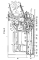
- Fig. 2 is a longitudinal sectional side view showing an image forming apparatus according to an embodiment of the present invention, including a sheet feed apparatus A and a laser beam printer B serving as a main unit which is combined with the sheet feed apparatus A.
- the sheet feed apparatus A is provided separately from the printer B as the main unit, and serves as an optional unit which is detachable from the printer B.
- the sheet feed apparatus A is placed on a base C, and the printer B as the main unit is placed on the sheet feed apparatus A.
- Projections 18 extending from the lower surface of the printer B are fitted in recesses 24 formed in an upper surface plate 21 of the sheet feed apparatus A, thereby combining the sheet feed apparatus A with the printer B.
- a sheet inlet 19 is formed in the bottom surface of the printer B corresponding to a nip position between a sheet pickup roller 10 and a sheet convey roller 12, both of which are located inside the printer B.
- the sheet inlet 19 of the sheet feed apparatus A is located above a pair of sheet convey rollers 28 and 55 located at the front side portion of the upper surface plate 21 of the sheet feed apparatus A.
- the printer B has a housing 1.
- the right end face in Fig. 2 is the front surface of the printer B.
- the housing 1 includes a front surface plate 1A.
- the front surface plate 1A can be pivoted about a hinge shaft 1B mounted on the lower side of the housing 1 and can be opened, as indicated by the alternate long and two short dashed line.
- the front surface plate 1A can be closed, as indicated by the solid line.
- the front surface plate 1A can be opened to largely expose the interior of the printer B in order to mount a process cartridge 2 into the printer B, or to remove it therefrom, or to perform inspection and maintenance operations.
- the process cartridge 2 includes a cartridge housing 2a which contains four image processing units, i.e., a photosensitive drum 3, a charging roller 4, a developing unit 5, and a cleaner 6.
- image processing units i.e., a photosensitive drum 3, a charging roller 4, a developing unit 5, and a cleaner 6.
- a laser beam scanner 7 is located deep in the housing 1.
- the laser beam scanner 7 comprises a semiconductor laser, a scanner motor 7a, a polygonal mirror 7b, and a lens system 7c.
- a laser beam L emitted from the scanner 7 almost horizontally propagates into the housing 2a through an exposure window 2b formed in the cartridge housing 2a mounted in the printer B.
- the laser beam L passes through an optical path formed between the cleaner 6 and the developing unit 5 located at upper and lower positions in the housing 2a.
- the laser beam L scans and exposes the surface of the photosensitive drum 3 in its axial direction.
- a multifeed tray 8 is attached to the lower end side of the front surface plate 1A, extends outward and is inclined upward from its proximal end to its distal end.
- a plurality of sheets S can be simultaneously set on the multifeed tray 8.
- the tray 8 can be pivoted about a hinge shaft 8a at the proximal end of the tray 8 to come close to the front surface plate 1A, when it is not used.
- An opening 9 is formed at the lower side of the printer front surface plate 1A. The proximal end of the multifeed tray 8 corresponds to this opening.
- the sheet pickup roller 10 is disposed in the lower portion inside the front surface plate 1A.
- a sheet separation pad 11 is located in contact with the lower side of the sheet pickup roller 10.
- a convey roller 12 is in contact with the left side of the sheet pickup roller 10.
- the convey roller 12 is disposed in the printer housing 1.
- a transfer roller 13 is located above the pickup roller 10 inside the front surface plate 1A.
- a pair of fixing rollers 15a and 15b are disposed in the upper portion inside the front surface plate 1A.
- a sheet guide plate 14 is located between the transfer roller 13 and the pair of fixing rollers 15a and 15b.
- a sheet delivery roller 16 is located at the sheet outlet.
- a tray 17 is located at the sheet outlet.
- the members 8 to 11 and 13 to 17 are located on the side of the printer front surface plate 1A.
- the sheet pickup roller 10 In a closed state of the front surface plate 1A with respect to the printer housing 1, as indicated by the solid line, the sheet pickup roller 10 is in contact with the sheet convey roller 12 disposed in the printer housing 1, and the transfer roller 13 is in contact with the right side of the photosensitive drum 3 in the process cartridge 2 mounted in the printer housing 1.
- the photosensitive drum 3 When an image formation start signal is inputted to a printer control system, the photosensitive drum 3 is rotated counterclockwise, as indicated by an arrow, at a predetermined peripheral velocity. The outer surface of the photosensitive drum 3 is uniformly charged by the charging roller 4 to a predetermined polarity (i.e., a positive or negative polarity).
- the charging roller 4 is a conductive member to which a predetermined voltage is applied.
- the photosensitive drum 3 is charged by this roller in accordance with a so-called contact (or direct) charging scheme.
- the charging roller 4 may be driven by the photosensitive drum 3 or may be rotated in a direction opposite to that of the photosensitive drum 3. Alternatively, the charging roller 4 needs not be rotated, or may comprise a friction charging member or a corona charger.
- a pixel laser beam L corresponding to a time-serial electrical pixel signal of an image information output, emitted from the laser beam scanner 7 is incident on a uniformly charged exposed portion 3a of the photosensitive drum 3.
- the main scanning with the laser beam L is performed on the surface of the drum 3 in the axial direction, thereby forming a latent image of the image information on the surface of the photosensitive drum 3.
- the latent image on the surface of the drum 3 is converted into a toner image by a developing agent carried by a developing sleeve (or roller) 5a of the developing unit 5.
- the developing unit 5 includes a hopper 5b for storing a developing agent (toner) t , and a developing agent stirring/convey member 5c which is rotated in a direction of an arrow in order to stir the developing agent t in the hopper 5b and to continuously supply the developing agent to the developing sleeve 5a.
- the uppermost sheet S is separated by the pickup roller 10 which is rotated clockwise, and the separation pad 11.
- the sheet S is then fed in the printer B through the opening 9.
- the leading end of the sheet S is clamped at the nip portion between the pickup roller 10 and the convey roller 12, and is conveyed toward a contact portion (transfer unit) between the photosensitive drum 3 and the transfer roller 13 at the same speed as the peripheral velocity of the photosensitive drum 3.
- the leading end of the sheet S is detected by a sheet sensor PH located at a predetermined position in the sheet path between the pickup roller 10 and the transfer roller 13.
- the laser beam scanner 7 starts exposure and scanning (image information write operation) of the surface of the photosensitive drum 3 in accordance with image information, in response to the sheet leading end detection signal.
- a toner image on the photosensitive drum 3 is transferred to the sheet S at the transfer unit by a voltage (i.e., a voltage having a polarity opposite to that of the toner) applied to the transfer roller 13 and a pressure between the transfer roller 13 and the photosensitive drum 3.
- the voltage is applied to the transfer roller 13 when the leading end of the sheet S reaches the contact portion (transfer unit) between the photosensitive drum 3 and the transfer roller 13.
- the transfer roller 13 may be a corona charger.
- the sheet S which has passed through the transfer unit is separated from the surface of the photosensitive drum 3 and is guided to the guide plate 14. Then, the sheet S is guided to the pair of fixing rollers 15a and 15b.
- the roller 15a of the pair of fixing rollers 15a and 15b, which is brought into contact with the image surface of the sheet S comprises a heating roller incorporating a halogen heater.
- the roller 15b which is brought into contact with a non-image surface of the sheet S comprises an elastic press roller.
- the toner image is fixed on the sheet surface by heat and pressure.
- the image-formed product (print) is delivered by the delivery roller 16 onto the tray 17.
- a residual toner and other contaminants on the surface of the photosensitive drum 3 are cleaned by a cleaning blade 6a of the cleaner 6, where upon the photosensitive drum 3 is ready for the next image formation cycle.
- the sheet feed apparatus A comprises a sheet feeder 20 including at least a sheet feed means and its driving means, and a sheet cassette 40 serving as a sheet storage unit detachable from the sheet feeder 20.
- Fig. 4 is a plan view of the sheet feeder 20
- Fig. 5 is a front view thereof
- Fig. 6 is a longitudinal sectional side view thereof.
- the sheet feeder 20 includes a feeder upper surface plate 21, elongated hollow right and left stands 21R and 21L which are mounted on the right and left sides of the upper surface plate 21, and being parallel to each other, and pads 22 attached to the lower surfaces of the stands 21R and 21L.
- a sheet cassette storage space 23 (Fig. 5) is defined by the lower surface of the feeder upper surface plate 21, the upper surface of the base C, and the inner side surfaces of the right and left stands 21R and 21L.
- Holes (recesses) 24 formed in the feeder upper surface plate 21 are engaged with the corresponding projections 18 (Fig. 2) formed on the lower surface of the printer B to position the printer B on the feeder 20. Therefore, the sheet feed apparatus A is combined with the printer B.
- a sheet feed roller shaft 25 is rotatably supported between the stands 21R and 21L by bearings. Rollers 26 are mounted on the shaft 25 and spaced apart from each other at predetermined intervals. The rollers 26 serve as three sheet feeding means. Each roller 26 comprises a roller (D-shaped roller) having a sector-shaped section. Each roller 26 is normally stopped such that its notched portion 26a is directed downward (Figs. 2 and 6).
- a sheet convey roller shaft 27 is rotatably supported between the right and left stands 21R and 21L by bearings. Sheet convey rollers 28 are mounted on the shaft 27.
- the sheet feed roller shaft 25 is substantially parallel to the sheet convey roller shaft 27.
- the convey roller shaft 27 is located at the front end portion of the feeder upper surface plate 21, at a position nearer to the upstream side in the sheet feed direction.
- Arcuated portions 26b opposite to the notched portions of the rollers 26 mounted on the shaft 25 are partially exposed above the upper surface plate 21 through corresponding through holes 29 formed in the upper surface plate 21.
- a stepping motor 30 (Fig. 4) is arranged inside the right stand 21R to drive the feed rollers 26 and the convey rollers 28.
- a gear train is constituted by gears G1 to G5 which are meshed with each other.
- the gear G1 is an output gear of the motor 30.
- the gear G2 serves as an idler gear.
- the gear G3 is a clutch gear loosely fitted on the right end of the sheet feed roller shaft 25. Engagement/disengagement of the gear G3 is controlled by a one-revolution spring clutch 31.
- the gear G4 serves as an idler gear.
- the gear G5 is a convey roller shaft gear integrally mounted on the right end of the sheet convey roller shaft 27.
- the output gear G1 is rotated counterclockwise.
- the gears G2 to G5 interlocked with the gear G1 are then rotated.
- the idler gears G2 and G4 are rotated clockwise, while the clutch gear G3 and the convey roller shaft gear G4 are rotated counterclockwise.
- the clutch gear G3 is disengaged from the shaft 25 and idles on the shaft 25. In this state, a rotational force is not transmitted to the sheet feed roller shaft 25, and the feed rollers 26 are kept stopped.
- the solenoid plunger 31a is temporarily energized, the clutch 31 is actuated and the clutch gear G3 is engaged with the shaft 25.
- the shaft 25 is rotated counterclockwise. Therefore, the sheet feed rollers 26 are rotated counterclockwise (Fig. 6). Upon one revolution of the shaft 25, i.e. the rollers 26, the clutch is disengaged, i.e. the shaft 25 and therefore the rollers 26 are stopped.
- the sheet convey roller shaft 27 and, therefore, the sheet convey rollers 28 are kept rotated counterclockwise by the gears G1 to G5 regardless of ON/OFF control of the spring clutch 31 while the motor 30 is kept driven.
- Energization lead wires 30a and 31b are connected to the motor 30 and the solenoid plunger 31a, respectively.
- electrical coupling members (not shown) of the sheet feed apparatus A and the printer B are coupled to each other.
- the motor 30 and the solenoid plunger 31a are connected to a control circuit (not shown) in the printer B through the lead wires 30a and 31b.
- a plug (not shown) connected to the terminals of the lead wires 30a and 31b may be inserted into a socket (not shown) in the printer B to connect the motor 30 and the solenoid plunger 31a to the control circuit of the printer B, when the printer B is normally set on the sheet feed apparatus A.
- Guide grooves 32 (Figs. 5 and 6) are symmetrically formed at the inner surfaces of the right and left stands 21R and 21L to mount the sheet cassette 40 into the printer or to remove it therefrom.
- Cam grooves 33 are symmetrically formed at the inner surfaces of the front end portions of the right and left stands 21R and 21L.
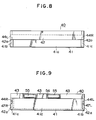
- Fig. 7 is a plan view of the sheet cassette
- Fig. 8 is a front view thereof
- Fig. 9 is a rear view thereof
- Fig. 10 is a left side view thereof
- Fig. 11 is a longitudinal sectional side view thereof.
- the cassette 40 includes a main case 41 having an open upper surface and a rectangular section.
- the case 41 includes a front wall 41a, a left side wall 41b, a right side wall 41c, a rear wall 41d, and a bottom plate 41e.
- a handle 42 is attached to the outer surface of the front wall 41a.
- a sheet guide plate 43 is mounted on the inner surface of the front wall 41a and is inclined upward from its proximal end to its distal end. Elongated flanges 44L and 44R extend outward from the upper sides of the left and right side walls 41b and 41c of the case along the longitudinal direction of the walls 41b and 41c.
- the case 41 (41a to 41e), the handle 42, the guide plate 43, the left and right elongated flanges 44L and 44R are constituted by a single resin molded member.
- An intermediate plate 45 is stored in the case 41.
- the front end of the intermediate plate 45 can be vertically pivoted about a rear side 45a.
- the sheets are stacked on the intermediate plate 45 and are stored in the case 41.
- An L-shaped pressure lever 46 (Figs. 2 and 11) serves as a pressure transmitting member for vertically pivoting the intermediate plate 45.
- the lever 46 can be pivoted about a shaft 46a mounted at the front end of the intermediate plate 45.
- One horizontal arm 46b is located below the lower surface of the front end portion of the intermediate plate 45.
- the lever 46 is pivoted clockwise about the shaft 46a, the horizontal arm 46b is raised, and the intermediate plate 45 is pivoted upward about the rear side 45a (from a position shown in Fig. 11 to a position shown in Fig. 2).
- a pressure shaft 47 is located in front of the lever 46.
- the left and right ends of the shaft 47 are fitted in symmetrical oblique slots 48 formed in left and right side walls 41b and 41c of the case, respectively.
- Left and right end portions 47L and 47R (Figs. 9 and 10) of the shaft 47 are exposed outside the left and right side walls.
- a tension coil spring 49 is hooked between the pressure shaft 47 and a vertical arm 46c of the lever 46.
- a pair of right and left separation pawls 50 separate the uppermost sheet from the remaining sheets, and are mounted on the distal end portions of levers 52 which can be pivoted about shafts 51.
- the pair of right and left separation pawls 50 correspond to the right and left corners of the leading end of the uppermost sheet of the sheets S stacked on the intermediate plate 45 in the case 41.
- Lever extended portions 53 are formed by extending the distal end portions of the levers 52 over the positions of the separation pawls 50, respectively.
- the extended portions 53 are located above the pressure shaft 47. In the state (Fig. 11) in which the sheet cassette 40 is removed from the sheet feeder 20, the extended portions 53 are placed on the pressure shaft 47 whose end portions are pulled to the upper end positions of the oblique slots 48.
- the levers 52 are held to be almost horizontal, and their downward pivotal movement is prevented. As a result, downward movement of the pawls 50 is also prevented.
- the sheet convey rollers 55 are driven rollers which are paired with the sheet convey rollers 28 serving as driving rollers (Fig. 2) on the feeder 20 side.
- the sheet convey rollers 55 are located at positions corresponding to the sheet convey rollers 28 in the feeder 20, and are brought into contact therewith.
- the rollers 55 are biased by a biasing means (not shown) toward the rollers 28 and, therefore, are in contact with the rollers 28 at a predetermined pressure.
- a stacked sheet side press member 56 (Fig. 7) is mounted inside the left side wall 41b of the case 41, and a biasing spring plate 57 urges the side press member 56 against the side surfaces of the stacked sheets at a predetermined pressure.
- Stacking and storage (to be described in detail later) of the sheets S in the sheet cassette 40 are performed through the upper surface opening of the case 41 after the cassette 40 is removed from the feeder 20.
- the intermediate plate 45 in the case 41 is laid on the inner bottom surface, i.e. located at the lowermost pivotal position, as described above.
- the extended portions 53 of the levers 52 having the separation pawls 50 are supported on the pressure shaft 47 which is pulled upward to the upper end positions of the oblique slots 48.
- the levers 52 are kept almost horizontal and their downward movement is prevented. Therefore, the levers 52 are located near the upper surface opening of the case 41. Spaces between the front end of the intermediate plate 45 and the separation pawls 50 are kept large, and the sheets S can be quickly stored into the case 41.
- the separation pawl 109e is stabilized at the uppermost level at the front end of the intermediate plate 109b or the leading end of the sheet S, which is always biased upward by the spring 109d.
- the sheets S are replenished into the case 109a while the intermediate plate 109b is moved downward against the biasing force of the spring 109d so as to offset the separation pawl 109e.
- Operability for sheet replenishment is degraded, as previously described.
- the cassette 40 of the present invention can eliminate this drawback.
- the sheet cassette 40 is mounted into the feeder 20 as follows.
- the cassette 40 is inserted (in a direction of an arrow X in Fig. 2) from the front surface of the feeder 20 into the sheet cassette storage space 23 (Fig. 5) defined by the lower surface of the upper surface plate 21, the upper surface of the base C, and the inner side surfaces of the right and left stands 21R and 21L of the feeder 20.
- the rear surface wall 41d of the cassette 40 is a leading end during insertion, and the elongated flanges 44R and 44L at the right and left sides of the cassette are fitted in the corresponding guide grooves 32 formed at the inner surfaces of the right and left stands 21R and 21L.
- the lower surfaces of projections 42a of the handle 42 on the front surface of the cassette abut against distal end portions 32a (Figs. 4 and 6) of the guide grooves 32, and further insertion of the cassette 40 can be prevented.
- the cassette 40 can be set in the feeder 20 at a proper insertion position. In this mounting state, the front end (i.e. the trailing end) of the cassette 40 is almost aligned with the front surface of the printer B, and an extended portion of the cassette 40 outside the printer B can be eliminated.
- the extended portions P and P′ of the trailing ends of the conventional cassettes in Fig. 1 toward the front side of the printer can be eliminated, thereby improving the outer appearance.
- the maximum insertion distance l1 of the cassette 40 into the feeder 20 is set to be larger than the size l2 of the feeder 20 in the cassette mounting direction.
- the cassette 40′ having a length larger than the size l2 can be inserted and mounted into the feeder 20.
- the rear end (i.e., the leading end) of the cassette 40′ extends as indicated by the alternate long and short dashed line in Fig. 3, thus exposing the extended portion P′ outside the rear portion of the feeder 20 or the printer B serving as the main unit.
- the outer appearance can be improved.
- the sheet feed rollers 26 located on the side of the upper surface plate 21 of the feeder 20 are rollers (D-shaped rollers) each having a sector-shaped section. Each roller 26 is stopped while its notched portion 26a is directed downward. Therefore, when the cassette 40 is inserted into the feeder 20, the upper side of the rear wall 41d of the case 41 passes under the notched portions 26a of the sheet feed rollers 26, and is not in contact therewith.
- the intermediate plate 45 does not receive an upward pivotal force from the pressure lever 46 until the cassette 40 is sufficiently inserted into the feeder 20 and normally mounted therein.
- the intermediate plate 45 is kept laid on the inner surface of the bottom plate 41e of the case 41, as shown in Fig. 11.
- the sheets S on the intermediate plate 45 are horizontally stored in the case 41.
- the upper surface of the uppermost sheet of the sheets S stacked in the case 41 is separated from the notched portions 26a of the sheet feed roller 26. No interference between the upper surface of the uppermost sheet S in the cassette 40 and the feed rollers 26 occurs.
- the feed rollers 26 in the feeder 20 are constituted by rollers each having a sector-shaped section, and the notches 26a are normally directed downward. Therefore, the sheet cassette storage space 23 defined by the lower surface of the upper surface plate 21, the upper surface of the base C, and the inner side surfaces of the right and left stands 21R and 21L can have a sufficient height. Therefore, the capacity for storing the sheet cassette 40 can be increased.
- the right and left end portions 47R and 47L of the pressure shaft 47 extending outward from the right and left side walls 41c and 41b of the cassette 40 are respectively engaged with the cam grooves 33 formed at the inner surfaces of the right and left stands 21R and 21L of the feeder 20, immediately before the cassette 40 is normally mounted into the feeder 20 upon insertion of the cassette 40 into the feeder 20.
- the right and left end portions 47R and 47L of the pressure shaft 47 receive a downward force by the insertion force of the cassette 40 along the cam grooves 33.
- the shaft 47 is moved downward since its both ends fitted in the oblique slots 48 are moved from the upper end points to the lower end points.
- the pressure lever 46 is pivoted clockwise about the shaft 46a by the tension coil spring 49.
- the horizontal arm 46b of the lever 46 is raised, and the intermediate plate 45 which supports the sheets S is pivoted about the rear side 45a so as to be inclined from the rear side to the front side.
- both ends of the pressure shaft 47 reach the lower end points. More specifically, the right and left end portions 47R and 47L are held by lower ends 33a (Fig. 5) of the cam grooves 33.
- the sheet convey rollers 55 in the cassette 40 are respectively in contact (Fig. 2) with the front sides of the sheet convey rollers 28 in the feeder 20, when the cassette 40 is completely mounted into the feeder 20.
- Fig. 2 shows positions and states of the respective members of the sheet feed apparatus A, when the cassette 40 is perfectly mounted into the feeder 20.
- the stepping motor 30 in the feeder 20 is energized and is rotated.
- the gears G1 to G5 are rotated, and the sheet convey rollers 28 are rotated counterclockwise in Fig. 2.
- the sheet convey rollers 55 of the cassette 40 which are brought into contact with the rollers 28 and paired therewith are driven.
- the sheet feed rollers 26 are kept stopped since the one-revolution spring clutch 31 is kept in a disengaged state. Thereafter, when the solenoid plunger 31a of the feeder 20 is temporarily energized by the control circuit of the printer in accordance with a sheet feed start signal, the spring clutch 31 is engaged, and the sheet feed rollers 26 are rotated clockwise (Fig. 2) by one revolution. Upon one revolution of the feed rollers 26, the arcuated portions 26b of the rollers 26 are brought into contact with the upper surface of the uppermost sheet of the sheets stacked on the intermediate plate 45.
- a feed force in a direction opposite to the direction X for mounting the cassette 40 in the feeder 20 acts on the upper surface of the uppermost sheet.
- the uppermost sheet is separated from the other sheets S by the separation pawls 50 and is fed in a direction of the front wall 41a of the cassette 40.
- the leading end of the fed sheet S is guided by the guide plate 43 and gripped by the nip portion between the pair of sheet feed rollers 28 and 55 from the lower direction. Then, the sheet S is conveyed upward and is fed into the printer B through the sheet inlet 19. The sheet S fed into the printer B is gripped by the nip portion between the feed and convey rollers 10 and 12 in the printer B above a guide plate 19a. The sheet S is then fed to the transfer roller 13.
- An image formation operation in the printer B is the same as that in the sheet feed mode of the multifeed tray 8, as previously described.
- each sheet S stored in the cassette 40 mounted in the feeder 20 is fed to the printer B, and an image is formed on the fed sheet S.
- the intermediate plate 45 When the number of sheets S stacked on the cassette 40 is decreased, the intermediate plate 45 is pivoted upward upon clockwise pivotal movement of the pressure lever 46 by a charged force of the tension coil spring 49.
- the vertical level of the uppermost sheet S on the intermediate plate 45 at the leading end of the sheet S is kept at a predetermined level. Therefore, stable separation and feeding of each sheet S can be performed.
- the right and left end portions 47R and 47L of the pressure shaft 47 in the cassette 40 are respectively disengaged from the cam grooves 33 at the inner side surfaces of the right and left stands 21R and 21L of the feeder 20.
- the pressure shaft 47 can freely be moved.
- a clockwise biasing force is released from the pressure lever 46.
- the lever 46 is pivoted counterclockwise by the weight of the intermediate plate 45 and the sheets S stacked thereon.
- the intermediate plate 45 is again laid on the inner bottom surface of the case 41.
- the pressure shaft 47 is returned to the initial state in which both the end portions of the shaft 47 are kept at the upper end positions.
- the extended portions 53 are supported on the pressure shaft 47 which is returned to the upper end point and is kept almost horizontal.
- the sheet feed apparatus A of this embodiment is provided as an optional unit which can be detachably added to the main unit B such as a printer or copying machine, as needed.
- Each sheet feed roller 26 has a sector-shaped section to allow longer sliding of the sheet cassette 40 into the feeder 20. Therefore, the sheet feed apparatus A can entirely be set below the main unit B. Due to the sheet feed apparatus A, the height of the main unit B is only slightly increased, and an extended portion of the cassette 40 outside the front side of the main unit B can be eliminated even in an optional arrangement.
- the operability of the sheet feed apparatus A is equivalent to that of the main unit B, and the sheet feed apparatus A is matched with the main unit B as regards design, thereby providing excellent operability and design.
- the feed direction of the sheets S stacked in the cassette 40 mounted into the feeder 20 is opposite to the direction for mounting the cassette 40 into the feeder 20. Therefore, the cassette 40 can easily be mounted into the main unit B or removed therefrom from the front side, and the operator needs not to walk to the rear side of the main unit B, even upon occurrence of jamming, thus resulting in convenience.
- the sheet feed apparatus A consisting of the feeder 20 and the cassette 40 is located below the main unit B, jamming troubleshooting and other troubleshooting operations can be performed on the front side, even if the cassette 40 has a long mounting stroke. This can be realized because the mounting direction of the cassette 40 into the feeder 20 is opposite to the feed direction of the sheets S.
- the sheet feed apparatus A consisting of the feeder 20 and the cassette 40 is located below the main unit B, the height of the system is only slightly increased by the sheets S stacked and stored in the cassette 40.
- the main unit B is not adversely affected by this arrangement. That is, design flexibility can be facilitated, and system expansion can be achieved by slightly modifying the design specifications.
- the sheet convey rollers 55 in the cassette 40 may comprise driving rollers as the rollers 28 in the feeder 20.
- the spring force for lifting the intermediate plate 45 is used to confirm a click at the end of mounting of the cassette 40, or to prevent the cassette 40 from removal.
- An additional spring and a cassette removal mechanism need not be arranged in the cassette 40 and the feeder 20, thus realizing a low-cost arrangement.
- the spring 49 may be arranged at the front end portion of the cassette in the sheet feed direction to minimize the thickness of the cassette 40. Therefore, the sheet feed apparatus A and hence the main unit B can be made compact.
- a sheet feed apparatus A is placed on a printer B serving as a main unit.
- the sheet feed apparatus A comprises a sheet feeder 200 and a sheet cassette 240 which can be detachably mounted into the sheet feeder 200 by elongated flanges 244R and 244L and guide grooves 232.
- the cassette 240 can be inserted into the feeder 200 and can be removed therefrom from the front side.
- Fig. 12(A) shows a state in which the sheet cassette 240 is mounted into the feeder 200
- Fig. 12(B) shows a state in which the sheet cassette 240 is being mounted into the feeder 200 or removed therefrom.
- Sheets S are stacked on an intermediate plate 245 in the cassette 240.
- the front end of the intermediate plate 245 is lifted by a spring 249a.
- Separation pawls 250 are provided at the right and left corners of the leading end of the uppermost sheet of the stacked sheets S.
- the sheet S is fed into the printer B from a sheet outlet 240a in the bottom surface of the cassette 240 to a sheet inlet 201a formed in the upper surface of the printer B.
- an image transfer unit i.e. a corona charger
- the feeder 200 in the sheet feed apparatus A may be permanently mounted on the upper surface plate of the printer B serving as a main unit.
- the feeder 200 may be prepared as an optional unit and detachably mounted on the upper surface plate. In this case, various types of sheets can be fed by replacing the feeders 200.
- the sheet path can be shortened as compared with a conventional arrangement.
- the substantially vertical guide 243b is formed in the cassette 240 which is detachably mounted into the feeder 200. During a jamming troubleshooting operation, the cassette 240 is pulled out of the feeder 200 to open the sheet path, thereby facilitating the processing.
- the cassette 240 is inserted and mounted into the feeder 200 by using the feeder front surface side as a reference side.
- the rear end portion of the cassette 240 extends outside the rear end surface of the feeder 200 or the printer B serving as the main unit.
- a power source cord H1, an interface cord H2, and the like extend from the rear end face of the printer B serving as the main unit, no problem is posed.
- the rear surface of the printer B cannot be brought into contact with a wall surface J or the like due to the presence of cords and the like on the rear surface of the printer B.
- a given distance is required between the rear surface of the printer B and the wall surface J, and, therefore, an extended portion P of the rear end portion of the cassette 240 will not reduce the effective installation space. To the contrary, an extended portion can be eliminated from the front side, thus improving front-side design and operability.
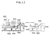
- An elastic plate member such as a leaf spring, a molded member, a MylarTM sheet, or a sheet member 455′ is used instead of the rollers 55 (first embodiment), which serves as a sheet convey member arranged in a cassette 440.
- the elastic plate or sheet member 455′ which serves as the sheet convey member in the cassette 440 is brought into contact with sheet convey rollers 428 in the feeder 420.
- One or both of the sheet guide members in front of and behind the sheet convey rollers may be utilized.
- the sheet S is then conveyed in a substantially vertical direction.
- the arrangement of this embodiment is inexpensive, and downstream and upstream guide operations with respect to the sheet convey rollers 428 can be assured.
- each convey roller 426 needs not to be a roller having a sector-shaped section, but can be a roller having a circular section, which is controlled to be brought into contact with or separated from the sheet S as in this embodiment.
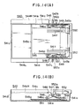
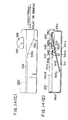
- Figs. 14(A) to 14(D) show still another embodiment of the present invention, in which Fig. 14(A) is a plan view thereof, Fig. 14(B) is a longitudinal side sectional view, and Fig. 14(C) is a view showing an upward cam surface and a back-and-forth guide groove.
- An intermediate plate 545 in a main case 541 of a cassette 540 is vertically pivotable about its rear end 545a.
- a spring mechanism 545b is arranged at each of the right and left side of the intermediate plate 545.
- Pressure levers 546 vertically pivotable about shafts 546a are mounted on inner surfaces of right and left side walls 541c and 541b of the main case 541, respectively.
- Pressure shafts 547 are fixed to distal end portions of the right and left pressure levers 546.
- Outer end portions (cam followers) 547R and 547L of the pressure shafts 547 are exposed outside the right and left side walls 541c and 541b of the main case 541 through arcuated slots 548 having the shafts 546a of the levers 546 as their centers.
- each coil spring 549 is hooked to a corresponding one of the spring mechanisms 545b of the intermediate plate 545, and the other ends of the springs 549 are locked by the corresponding pressure shaft 547 (or pressure lever 546).
- a pair of right and left sheet separation pawls 550 are mounted on distal end portions of levers 552 vertically pivotable about shafts 551 at the inner surfaces of the right and left side walls 541c and 541b of the case 541.
- Each separation pawl lever 552 is biased downward (clockwise in Fig. 14(B)) about the shaft 551 by its own weight or a biasing spring (not shown).
- the pawls 550 are located at the right and left corners of the leading end of the uppermost one of the sheets stacked on the intermediate plate 545.
- Figs. 14(A) and 14(B) show a state in which the cassette 540 is removed from a feeder 520.
- the pressure shafts 547 can freely be moved.
- the intermediate plate 545 is laid on the inner bottom surface of the case 541 by its own weight.
- the pressure levers 546 are pivoted downward (clockwise in Fig. 14(B)) about the shafts 546a by the laid intermediate plate 545 via the coil springs 549 and the pressure shafts 547. Therefore, the pressure shafts 547 are stopped at the lower end positions of the slots 548.
- the distal end portions of the pressure levers 546 pivoted downward abut against engaging portions 552a of the separation pawl levers 552.
- An upward pivotal force (counterclockwise in Fig. 14(B)) about the shafts 551 acts on the separation pawl levers 552. Downward pivotal movement of the separation pawls 550 held at the uppermost positions can be prevented.
- a large space is formed between the front end of the intermediate plate 545 and each separation pawl 550, and sheets can easily be stored in the cassette main case 541.
- the sides of the sheets stacked on the intermediate plate 545 are regulated by width regulating plates 541f.
- Elongated flanges 544R and 544L of the cassette 540 are engaged with corresponding guide grooves 532 formed in the feeder 520 (Fig. 14(C)) to insert the cassette 540 into the feeder 520.
- the end portions 547R and 547L serving as cam followers on the cassette 540 come into engagement with upward cam surfaces 533 formed in the feeder 520 immediately before the mounting of the cassette 540 into the feeder 520 is completed.
- the end portions 547R and 547L are moved upward along the arcuated slots 548 toward the upper end positions.
- the end portions 547R and 547L are stabilized in recesses 533a of the cam surfaces 533.
- Fig. 14(D) shows a state in which the cassette 540 is perfectly mounted into the feeder 520.
- the springs 549 and the like are arranged in its side areas, and the thickness of the cassette 540 can be minimized.
- the construction of the sheet feed apparatus A and hence the main unit B can be made compact.
- the cassette includes a means for urging the sheet toward the feed rollers.
- the urging means can be set to correspond to each cassette currently mounted in the main unit, and an optimal feed pressure can advantageously act on the sheet.
- the sheet urging means of the cassette also serves as a locking means for locking the cassette when the cassette is perfectly mounted into the feeder as main unit. Therefore, the feeder only has a simple cam mechanism. No locking means need be arranged in the feeder, and a low-cost, compact cassette feeder can be obtained.
Landscapes
- Physics & Mathematics (AREA)
- General Physics & Mathematics (AREA)
- Engineering & Computer Science (AREA)
- Mechanical Engineering (AREA)
- Sheets, Magazines, And Separation Thereof (AREA)
Claims (14)
- Bilderzeugungsgerät mit einem Hauptteil (1), mit einer Blattspeichereinrichtung (40) zur Speicherung von Blättern (S) in dieser, mit Einrichtungen (26) zum Fördern eines in der genannten Blattspeichereinrichtung gespeicherten Blatts, mit Einrichtungen (3, 10, 12 - 16, 19a, 28, 55) zum Transport des durch die erwähnten Fördereinrichtungen geförderten Blatts durch eine Bilderzeugungssektion (3, 13) hindurch zu einem Auslaßteil (17) des besagten Bilderzeugungsgeräts, mit einer Einrichtung (1A), um die genannten Transporteinrichtungen teilweise zu lagern, wobei die Lagerungseinrichtung (1A) derart eingerichtet ist, daß sie in einer vorbestimmten Richtung mit Bezug zu dem besagten Hauptteil (1) des erwähnten Bilderzeugungsgeräts zu öffnen ist, und mit Mitteln (32) zur Führung der genannten Blattspeichereinrichtung derart, daß sie von dem besagten Bilderzeugungsgerät in der erwähnten vorbestimmten Richtung ausbaubar ist, dadurch gekennzeichnet, daß die genannten Transporteinrichtungen im wesentlichen vertikal mit Bezug zu dem besagten Bilderzeugungsgerät angeordnet sind, um das Blatt im wesentlichen vertikal zu transportieren, und daß die erwähnten Fördereinrichtungen eingerichtet sind, um das Blatt in einer zu einer Einbaurichtung der genannten Blattspeichereinrichtung entgegengesetzten Richtung zu fördern.
- Gerät nach Anspruch 1, dadurch gekennzeichnet, daß ein Teil (10) der genannten Transporteinrichtungen (3, 10, 12 - 16, 19a, 28, 55) so angeordnet ist, um auch als eine weitere Fördereinrichtung zum Fördern der Blätter (S) zu dienen.
- Gerät nach Anspruch 2, dadurch gekennzeichnet, daß die genannten Transporteinrichtungen (3, 10, 12 - 16, 19a, 28, 55) eine Walze (10) umfassen, die einer weiteren Walze (12) an einem Transportsegment von dieser und einem Reibungselement (11) an einem Fördersegment von dieser gegenüberliegt.
- Gerät nach Anspruch 3, das ferner eine Blattbahn zur Führung eines durch das genannte Reibungselement (11) getrennten Blatts (S) zu dem erwähnten Transportsegment enthält, wobei die besagte Blattbahn stromab von dem genannten Fördersegment angeordnet ist.
- Gerät nach Anspruch 4, gekennzeichnet durch eine Blattabgabeschale (8), die stromauf von dem genannten Fördersegment angeordnet ist.
- Gerät nach Anspruch 5, dadurch gekennzeichnet, daß die erwähnten Fördereinrichtungen (26) und die erwähnten Führungsmittel (32) in einer Blattzuführeinheit (A) enthalten sind, die mit Bezug zu dem besagten Hauptteil (1) eine einzige Einheit ist.
- Gerät nach einem der vorhergehenden Ansprüche, dadurch gekennzeichnet, daß die genannte Blattspeichereinrichtung (40) Mittel (45) zur Stapelung der Blätter (S) und Mittel (55) zum Transport der Blätter (S) umfaßt, wobei die genannten Transportmittel (55) stromab von den besagten Stapelmitteln (45) angeordnet sind.
- Gerät nach Anspruch 7, dadurch gekennzeichnet, daß die genannten Transportmittel (55) imstande sind, die Blätter (S) durch eine in einem Bodenteil des besagten Hauptteils (1) ausgebildete Öffnung (19) hindurch zu dem besagten Hauptteil (1) zu führen.
- Gerät nach Anspruch 7, das ferner Federmittel (49), um die besagten Stapelmittel (45) zu den erwähnten Fördereinrichtungen (26) hin zu drücken, und eine Einrichtung (47), um die besagten Federmittel bei Einbau der genannten Blattspeichereinrichtung (40) in die erwähnte Blattzuführeinheit (A) einem Druck auszusetzen, enthält.
- Gerät nach Anspruch 9, dadurch gekennzeichnet, daß die genannte Blattspeichereinrichtung (40) ein Kurveneingriffsglied (47, 47R, 47L) umfaßt, das mit einer Steuerkurvenfläche (33) der erwähnten Blattzuführeinheit (A) in Eingriff ist, wenn die genannte Blattspeichereinrichtung in die erwähnte Blattzuführeinheit eingebaut wird, wobei die besagten Federmittel (40) ein mit dem genannten Kurveneingriffsglied (47, 47R, 47L) verbundenes Ende haben und das andere Ende mit den besagten Stapelmitteln (45) über ein übertragungsglied (46) verbunden ist derart, daß die besagten Stapelmittel (45) mit Hilfe des erwähnten Übertragungsglieds durch eine Kraft der besagten Federmittel vertikal aufwärts bewegt werden, welche durch den erwähnten Eingriff des genannten Kurveneingriffsglieds mit der besagten Steuerkurvenfläche erhalten wird, wenn die genannte Blattspeichereinrichtung in die erwähnte Blattzuführeinheit eingebaut wird.
- Gerät nach Anspruch 10, dadurch gekennzeichnet, daß die genannte Blattspeichereinrichtung (40) eine mit einer vorlaufenden Kante eines obersten Blatts (S) in Eingriff zu bringende Einzelblatt-Trennklinke (51 - 53) umfaßt, welche genannte Einzelblatt-Trennklinke mit einem Anlageteil (53) versehen ist, das funktionell mit dem genannten Kurveneingriffsglied (47, 47R, 47L) verbunden ist, wobei die erwähnten Stapelmittel (45) in einer untersten Position durch ihr Eigengewicht angeordnet werden, wenn die genannte Blattspeichereinrichtung nicht in der erwähnten Blattzuführeinheit (A) montiert ist, so daß die genannte Einzelblatt-Trennklinke zu einer höchsten Position von den erwähnten Stapelmitteln mit Hilfe des genannten Übertragungselements (46), der besagten Federmittel (49) und des genannten Kurveneingriffsglieds aufwärts bewegt wird.
- Gerät nach einem der vorhergehenden Ansprüche, dadurch gekennzeichnet, daß die genannte Lagerungseinrichtung (1A) an einem Seitenteil des erwähnten Bilderzeugungsgeräts angelenkt ist.
- Gerät nach einem der vorhergehenden Ansprüche, dadurch gekennzeichnet, daß die genannten Transporteinrichtungen (3, 10, 12 - 16, 19a, 28, 55) Mittel (10, 12, 28, 55) zum Transport der durch die erwähnten Fördereinrichtungen (26) zugeführten Blätter (S), eine Bilderzeugungssektion (3, 13), Mittel (15a, 15b, 16) zum Austrag der durch die genannte Bilderzeugungssektion bearbeiteten Blätter und Mittel (14, 19a) zur Führung der zugeführten Blätter sowie der bearbeiteten Blätter besitzen.
- Gerät nach Anspruch 13, dadurch gekennzeichnet, daß die genannten Transporteinrichtungen (10, 12), die erwähnte Bilderzeugungssektion (3, 13) und die genannten Führungsmittel (19a) jeweils aus zwei Elementen bestehen, die einander gegenüberliegend angeordnet sind, wobei die genannte Lagerungseinrichtung (1A) jeweils ein Element der genannten Transporteinrichtungen, der erwähnten Bilderzeugungssektion und der genannten Führungsmittel lagert.
Priority Applications (1)
| Application Number | Priority Date | Filing Date | Title |
|---|---|---|---|
| EP93113469A EP0574041B1 (de) | 1987-12-26 | 1988-12-23 | Bilderzeugungsgerät |
Applications Claiming Priority (8)
| Application Number | Priority Date | Filing Date | Title |
|---|---|---|---|
| JP62331144A JPH01172130A (ja) | 1987-12-26 | 1987-12-26 | シート材給送装置 |
| JP62331145A JP2556539B2 (ja) | 1987-12-26 | 1987-12-26 | 画像形成装置 |
| JP331145/87 | 1987-12-26 | ||
| JP62331142A JP2505838B2 (ja) | 1987-12-26 | 1987-12-26 | 画像形成装置 |
| JP62331141A JPH0825652B2 (ja) | 1987-12-26 | 1987-12-26 | 開閉可能な搬送手段を備える画像形成装置 |
| JP331141/87 | 1987-12-26 | ||
| JP331144/87 | 1987-12-26 | ||
| JP331142/87 | 1987-12-26 |
Related Child Applications (2)
| Application Number | Title | Priority Date | Filing Date |
|---|---|---|---|
| EP93113469A Division EP0574041B1 (de) | 1987-12-26 | 1988-12-23 | Bilderzeugungsgerät |
| EP93113469.6 Division-Into | 1993-08-24 |
Publications (3)
| Publication Number | Publication Date |
|---|---|
| EP0322818A2 EP0322818A2 (de) | 1989-07-05 |
| EP0322818A3 EP0322818A3 (en) | 1989-10-18 |
| EP0322818B1 true EP0322818B1 (de) | 1994-11-02 |
Family
ID=27480455
Family Applications (2)
| Application Number | Title | Priority Date | Filing Date |
|---|---|---|---|
| EP93113469A Expired - Lifetime EP0574041B1 (de) | 1987-12-26 | 1988-12-23 | Bilderzeugungsgerät |
| EP88121632A Expired - Lifetime EP0322818B1 (de) | 1987-12-26 | 1988-12-23 | Blattzuführgerät für ein Bilderzeugungssystem |
Family Applications Before (1)
| Application Number | Title | Priority Date | Filing Date |
|---|---|---|---|
| EP93113469A Expired - Lifetime EP0574041B1 (de) | 1987-12-26 | 1988-12-23 | Bilderzeugungsgerät |
Country Status (3)
| Country | Link |
|---|---|
| US (2) | US5002266A (de) |
| EP (2) | EP0574041B1 (de) |
| DE (2) | DE3855946T2 (de) |
Families Citing this family (61)
| Publication number | Priority date | Publication date | Assignee | Title |
|---|---|---|---|---|
| EP0285139B1 (de) * | 1987-03-31 | 1995-10-11 | Canon Kabushiki Kaisha | Bilderzeugungsgerät |
| US5247316A (en) * | 1987-03-31 | 1993-09-21 | Canon Kabushiki Kaisha | Laser beam printer having three-point support system |
| US5822578A (en) * | 1987-12-22 | 1998-10-13 | Sun Microsystems, Inc. | System for inserting instructions into processor instruction stream in order to perform interrupt processing |
| DE68920781T2 (de) * | 1988-06-17 | 1995-06-14 | Canon Kk | Bildaufzeichnungsgerät. |
| US5122841A (en) * | 1988-08-18 | 1992-06-16 | Canon Kabushiki Kaisha | Image forming apparatus |
| US5232214A (en) * | 1989-03-08 | 1993-08-03 | Minolta Camera Kabushiki Kaisha | Paper supplying apparatus and method using a detachable cassette |
| US5170950A (en) * | 1989-05-15 | 1992-12-15 | Sharp Kabushiki Kaisha | Feeding device |
| JP2574900B2 (ja) * | 1989-09-16 | 1997-01-22 | キヤノン株式会社 | 画像形成装置 |
| US5276489A (en) * | 1989-09-16 | 1994-01-04 | Canon Kabushiki Kaisha | Image forming apparatus with transfer roller with guide means which adjusts to movements of the roller |
| US5253015A (en) * | 1990-03-22 | 1993-10-12 | Konica Corporation | Sheet load system for image forming apparatus |
| US5201873A (en) * | 1990-07-04 | 1993-04-13 | Canon Kabushiki Kaisha | Sheet feeding apparatus having the ability to retract the sheet supply |
| JPH0473666A (ja) * | 1990-07-12 | 1992-03-09 | Minolta Camera Co Ltd | 画像作成装置 |
| JPH04164752A (ja) * | 1990-10-25 | 1992-06-10 | Mitsubishi Electric Corp | 複写機 |
| EP0487040B1 (de) * | 1990-11-23 | 1996-01-24 | Minolta Camera Kabushiki Kaisha | Bilderzeugungsgerät |
| JPH04190253A (ja) * | 1990-11-23 | 1992-07-08 | Minolta Camera Co Ltd | レーザビームプリンタ |
| US5280898A (en) * | 1991-02-27 | 1994-01-25 | Mita Industrial Co., Ltd. | Image forming apparatus having a front loading paper feeding member with an improved paper jam removing mechanism |
| JPH04286550A (ja) * | 1991-03-11 | 1992-10-12 | Canon Inc | シート材給送装置 |
| US5398108A (en) * | 1991-03-11 | 1995-03-14 | Canon Kabushiki Kaisha | Sheet supplying apparatus having a plurality of pressurizing means |
| JP2974444B2 (ja) * | 1991-04-22 | 1999-11-10 | キヤノン株式会社 | シート材給送装置 |
| KR940003112B1 (ko) * | 1991-10-25 | 1994-04-13 | 삼성전자 주식회사 | 전자사진방식을 이용한 기기에 사용되는 카세트 |
| IT1256512B (it) * | 1992-01-13 | 1995-12-07 | Olivetti Canon Ind Spa | Macchina fotocopiatrice con dispositivo ausiliario di alimentazione difogli. |
| JP2840517B2 (ja) * | 1992-06-02 | 1998-12-24 | キヤノン株式会社 | 給紙カセット及び画像形成装置 |
| DE69328736T2 (de) * | 1992-06-19 | 2001-03-29 | Canon K.K., Tokio/Tokyo | Vorrichtung zum Zuführen von Bögen |
| US5402221A (en) * | 1992-07-31 | 1995-03-28 | E. I. Du Pont De Nemours And Company | Guideplate assembly having substrate velocity control arrangement |
| US5391009A (en) * | 1993-10-29 | 1995-02-21 | Hewlett-Packard Company | Single motor actuation for automatic stack feeder system in a hardcopy device |
| JP3230948B2 (ja) * | 1994-10-03 | 2001-11-19 | キヤノン株式会社 | 画像形成装置 |
| KR0135453B1 (ko) * | 1995-05-18 | 1998-05-15 | 김광호 | 전자사진 현상 방식 화상형성 장치의 전원 절약 방법 |
| CH691767A5 (de) * | 1995-08-10 | 2001-10-15 | Rutishauser Data Ag | Deckeleinheit für eine Büromaschine. |
| JPH0967028A (ja) * | 1995-09-01 | 1997-03-11 | Ricoh Co Ltd | 給紙装置 |
| JP3504808B2 (ja) * | 1995-09-05 | 2004-03-08 | 富士ゼロックス株式会社 | 画像形成装置 |
| KR0174600B1 (ko) * | 1995-09-19 | 1999-04-01 | 김광호 | 폐토너 절감을 위한 감광드럼 전위 조절장치 및 방법 |
| KR100209517B1 (ko) * | 1996-05-25 | 1999-07-15 | 윤종용 | 급지용량을 가변시킬 수 있는 레이져빔 프린터 |
| US6490059B1 (en) | 1996-09-04 | 2002-12-03 | Hewlett-Packard Company | Rotatable sheet feed scanner and method for using the same |
| KR100211795B1 (ko) | 1996-11-08 | 1999-08-02 | 윤종용 | 레이저 빔 프린터의 보조 급지 장치용 구동장치 |
| DE69828088T2 (de) * | 1997-04-09 | 2005-12-01 | Seiko Epson Corp. | Dokumentenzuführvorrichtung für einen Drucker |
| JP3298611B2 (ja) * | 1997-05-29 | 2002-07-02 | セイコーエプソン株式会社 | 紙送り装置 |
| JP3371770B2 (ja) * | 1997-09-08 | 2003-01-27 | 富士ゼロックス株式会社 | 画像形成装置 |
| JP2000280570A (ja) * | 1999-03-31 | 2000-10-10 | Brother Ind Ltd | 画像形成装置 |
| US6415118B1 (en) * | 1999-09-28 | 2002-07-02 | Canon Kabushiki Kaisha | Image forming apparatus with inclined guide for sheet material |
| US6550760B1 (en) | 2000-10-18 | 2003-04-22 | Eastman Kodak Company | Spring nail for a sheet feeding device |
| US6581924B2 (en) * | 2001-06-13 | 2003-06-24 | Hewlett-Packard Development Co., L.P. | Roller gear over engagement protection for document feeder |
| JP4153184B2 (ja) * | 2001-09-17 | 2008-09-17 | 株式会社リコー | プリンタ |
| JP4870901B2 (ja) * | 2002-03-19 | 2012-02-08 | 富士ゼロックス株式会社 | シート処理装置 |
| JP4007277B2 (ja) * | 2003-07-22 | 2007-11-14 | ブラザー工業株式会社 | 画像形成装置 |
| US7292820B2 (en) * | 2003-07-30 | 2007-11-06 | Lexmark International, Inc. | Integrated media input tray including electronics |
| JP4138607B2 (ja) * | 2003-08-21 | 2008-08-27 | 株式会社東芝 | 画像形成装置 |
| US7435025B2 (en) * | 2004-03-05 | 2008-10-14 | Brother Kogyo Kabushiki Kaisha | Image recording apparatus |
| US20070248366A1 (en) * | 2006-04-19 | 2007-10-25 | Lexmark International, Inc. | Devices for moving a media sheet within an image forming apparatus |
| US20070248365A1 (en) * | 2006-04-19 | 2007-10-25 | Lexmark International, Inc. | Methods for moving a media sheet within an image forming device |
| US8020849B2 (en) | 2007-02-28 | 2011-09-20 | Brother Kogyo Kabushiki Kaisha | Image recording apparatus |
| US7699305B2 (en) | 2007-03-29 | 2010-04-20 | Lexmark International, Inc. | Smart pick control algorithm for an image forming device |
| KR101172398B1 (ko) * | 2007-08-03 | 2012-08-08 | 삼성전자주식회사 | 인쇄매체 공급장치 및 이를 포함하는 화상형성장치 |
| JP2010064804A (ja) * | 2008-09-08 | 2010-03-25 | Ricoh Co Ltd | 給紙装置及び画像形成装置 |
| EP2206665A1 (de) * | 2009-01-08 | 2010-07-14 | Sagem Communications Sas | Kassette für eine Druckvorrichtung |
| JP2011157160A (ja) * | 2010-01-29 | 2011-08-18 | Fujifilm Corp | 給紙装置及びプリント装置 |
| JP5189125B2 (ja) * | 2010-03-23 | 2013-04-24 | ブラザー工業株式会社 | シート搬送装置及び画像形成装置 |
| JP5765919B2 (ja) | 2010-11-15 | 2015-08-19 | キヤノン株式会社 | シート給送装置及び画像形成装置 |
| JP5370422B2 (ja) * | 2011-06-29 | 2013-12-18 | ブラザー工業株式会社 | 画像形成装置 |
| JP6789662B2 (ja) * | 2016-04-22 | 2020-11-25 | キヤノン株式会社 | 画像形成装置 |
| CN111615494B (zh) * | 2017-09-14 | 2022-05-06 | 京瓷办公信息系统株式会社 | 图像形成装置 |
| JP7148251B2 (ja) * | 2018-03-23 | 2022-10-05 | 富士通コンポーネント株式会社 | 記録紙カセット及びプリンタ装置 |
Citations (1)
| Publication number | Priority date | Publication date | Assignee | Title |
|---|---|---|---|---|
| EP0201711A2 (de) * | 1985-04-12 | 1986-11-20 | Hitachi, Ltd. | Bildaufnahmegerät |
Family Cites Families (15)
| Publication number | Priority date | Publication date | Assignee | Title |
|---|---|---|---|---|
| JPS56161562A (en) * | 1980-05-16 | 1981-12-11 | Canon Inc | Image recording device |
| JPS57156929A (en) * | 1981-03-19 | 1982-09-28 | Toshiba Corp | Paper supply device |
| US4531823A (en) * | 1981-04-17 | 1985-07-30 | Sanyo Electric Co., Ltd. | Electrostatic copying machine having removable paper path |
| JPS5878928A (ja) * | 1981-11-05 | 1983-05-12 | Canon Inc | 画像形成装置 |
| US4534643A (en) * | 1982-01-29 | 1985-08-13 | Tokyo Shibaura Denki Kabushiki Kaisha | Image forming apparatus |
| JPS58152642U (ja) * | 1982-04-04 | 1983-10-13 | 京セラミタ株式会社 | ソ−タ−付き静電写真複写機 |
| DE3335181A1 (de) * | 1982-09-29 | 1984-03-29 | Canon K.K., Tokyo | Blattzufuhrvorrichtung |
| GB2132942B (en) * | 1982-09-30 | 1987-07-29 | Canon Kk | Detachable parts of image-forming apparatus |
| US4838534A (en) * | 1982-10-25 | 1989-06-13 | Canon Kabushiki Kaisha | Paper feed apparatus |
| IT1212977B (it) * | 1983-02-10 | 1989-12-07 | Olivetti & Co Spa | Macchina copiatrice elettrofotogra fica |
| US4591884A (en) * | 1983-03-10 | 1986-05-27 | Canon Kabushiki Kaisha | Multi-function image recording apparatus |
| US4784274A (en) * | 1983-10-03 | 1988-11-15 | Kabushiki Kaisha Nippon Coinco | Bill device |
| DK151414C (da) * | 1983-11-03 | 1988-05-16 | Mercante Int As | Elektrofotografisk informationsskriver med xerografisk reproduktionssystem |
| JPS62299868A (ja) * | 1986-06-19 | 1987-12-26 | Canon Inc | 画像形成装置及びこの装置に使用するプロセスカートリッジ |
| JPH0198529A (ja) * | 1987-10-08 | 1989-04-17 | Fujitsu Ltd | 像形成装置 |
-
1988
- 1988-12-22 US US07/288,143 patent/US5002266A/en not_active Ceased
- 1988-12-23 EP EP93113469A patent/EP0574041B1/de not_active Expired - Lifetime
- 1988-12-23 EP EP88121632A patent/EP0322818B1/de not_active Expired - Lifetime
- 1988-12-23 DE DE3855946T patent/DE3855946T2/de not_active Expired - Fee Related
- 1988-12-23 DE DE3852014T patent/DE3852014T2/de not_active Expired - Fee Related
-
1993
- 1993-03-25 US US08/036,808 patent/USRE35341E/en not_active Expired - Lifetime
Patent Citations (1)
| Publication number | Priority date | Publication date | Assignee | Title |
|---|---|---|---|---|
| EP0201711A2 (de) * | 1985-04-12 | 1986-11-20 | Hitachi, Ltd. | Bildaufnahmegerät |
Also Published As
| Publication number | Publication date |
|---|---|
| DE3855946D1 (de) | 1997-07-24 |
| DE3852014D1 (de) | 1994-12-08 |
| EP0574041A3 (de) | 1994-01-05 |
| EP0322818A2 (de) | 1989-07-05 |
| EP0322818A3 (en) | 1989-10-18 |
| DE3852014T2 (de) | 1995-03-30 |
| USRE35341E (en) | 1996-10-01 |
| DE3855946T2 (de) | 1998-01-29 |
| EP0574041B1 (de) | 1997-06-18 |
| US5002266A (en) | 1991-03-26 |
| EP0574041A2 (de) | 1993-12-15 |
Similar Documents
| Publication | Publication Date | Title |
|---|---|---|
| EP0322818B1 (de) | Blattzuführgerät für ein Bilderzeugungssystem | |
| EP0774434B1 (de) | Vorrichtung zum Zuführen von Bögen | |
| US20140049001A1 (en) | Image forming apparatus | |
| US5030991A (en) | Jam detection and clearance system for duplex copiers | |
| JPH0244734B2 (de) | ||
| CN102120530A (zh) | 供纸结构件和安装有供纸结构件的图像形成装置 | |
| JP3639614B2 (ja) | 多機能画像形成装置 | |
| EP0367200A2 (de) | Bogenzuführvorrichtung | |
| US8913309B2 (en) | Image reading apparatus and image forming apparatus | |
| JP2556539B2 (ja) | 画像形成装置 | |
| JP5481458B2 (ja) | シート搬送装置およびこれを備えた画像形成装置 | |
| JP2505838B2 (ja) | 画像形成装置 | |
| CN115196377A (zh) | 供纸装置以及图像形成装置 | |
| US12306569B2 (en) | Drive transmitter, drive device, and image forming apparatus | |
| JP2001002282A (ja) | シート搬送装置および画像形成装置 | |
| JPH0825652B2 (ja) | 開閉可能な搬送手段を備える画像形成装置 | |
| JPH01172129A (ja) | シート材給送装置 | |
| JP3426814B2 (ja) | 用紙給送装置 | |
| JP5942879B2 (ja) | 画像形成装置 | |
| JP3740863B2 (ja) | 画像形成装置 | |
| JPH11165899A (ja) | シート材給送装置、画像形成装置、ファクシミリ装置 | |
| JPH01172130A (ja) | シート材給送装置 | |
| JP2000118829A (ja) | 紙葉類搬送装置 | |
| JPH10333381A (ja) | 原稿読取装置を内蔵する画像形成装置 | |
| JPH09110216A (ja) | シート給送装置及び画像形成装置 |
Legal Events
| Date | Code | Title | Description |
|---|---|---|---|
| PUAI | Public reference made under article 153(3) epc to a published international application that has entered the european phase |
Free format text: ORIGINAL CODE: 0009012 |
|
| AK | Designated contracting states |
Kind code of ref document: A2 Designated state(s): DE FR GB IT |
|
| PUAL | Search report despatched |
Free format text: ORIGINAL CODE: 0009013 |
|
| AK | Designated contracting states |
Kind code of ref document: A3 Designated state(s): DE FR GB IT |
|
| 17P | Request for examination filed |
Effective date: 19900305 |
|
| 17Q | First examination report despatched |
Effective date: 19920423 |
|
| ITTA | It: last paid annual fee | ||
| GRAA | (expected) grant |
Free format text: ORIGINAL CODE: 0009210 |
|
| AK | Designated contracting states |
Kind code of ref document: B1 Designated state(s): DE FR GB IT |
|
| REF | Corresponds to: |
Ref document number: 3852014 Country of ref document: DE Date of ref document: 19941208 |
|
| ITF | It: translation for a ep patent filed | ||
| ET | Fr: translation filed | ||
| PLBE | No opposition filed within time limit |
Free format text: ORIGINAL CODE: 0009261 |
|
| STAA | Information on the status of an ep patent application or granted ep patent |
Free format text: STATUS: NO OPPOSITION FILED WITHIN TIME LIMIT |
|
| 26N | No opposition filed | ||
| REG | Reference to a national code |
Ref country code: GB Ref legal event code: IF02 |
|
| PGFP | Annual fee paid to national office [announced via postgrant information from national office to epo] |
Ref country code: FR Payment date: 20051208 Year of fee payment: 18 |
|
| PGFP | Annual fee paid to national office [announced via postgrant information from national office to epo] |
Ref country code: DE Payment date: 20051215 Year of fee payment: 18 |
|
| PGFP | Annual fee paid to national office [announced via postgrant information from national office to epo] |
Ref country code: GB Payment date: 20051221 Year of fee payment: 18 |
|
| PGFP | Annual fee paid to national office [announced via postgrant information from national office to epo] |
Ref country code: IT Payment date: 20061231 Year of fee payment: 19 |
|
| PG25 | Lapsed in a contracting state [announced via postgrant information from national office to epo] |
Ref country code: DE Free format text: LAPSE BECAUSE OF NON-PAYMENT OF DUE FEES Effective date: 20070703 |
|
| GBPC | Gb: european patent ceased through non-payment of renewal fee |
Effective date: 20061223 |
|
| REG | Reference to a national code |
Ref country code: FR Ref legal event code: ST Effective date: 20070831 |
|
| PG25 | Lapsed in a contracting state [announced via postgrant information from national office to epo] |
Ref country code: GB Free format text: LAPSE BECAUSE OF NON-PAYMENT OF DUE FEES Effective date: 20061223 |
|
| PG25 | Lapsed in a contracting state [announced via postgrant information from national office to epo] |
Ref country code: FR Free format text: LAPSE BECAUSE OF NON-PAYMENT OF DUE FEES Effective date: 20070102 |
|
| PG25 | Lapsed in a contracting state [announced via postgrant information from national office to epo] |
Ref country code: IT Free format text: LAPSE BECAUSE OF NON-PAYMENT OF DUE FEES Effective date: 20071223 |