EP0322864B1 - Spindel für eine Wickelhülse - Google Patents
Spindel für eine Wickelhülse Download PDFInfo
- Publication number
- EP0322864B1 EP0322864B1 EP88121729A EP88121729A EP0322864B1 EP 0322864 B1 EP0322864 B1 EP 0322864B1 EP 88121729 A EP88121729 A EP 88121729A EP 88121729 A EP88121729 A EP 88121729A EP 0322864 B1 EP0322864 B1 EP 0322864B1
- Authority
- EP
- European Patent Office
- Prior art keywords
- shaft
- tube
- protective cover
- nonstretchable
- sleeve
- Prior art date
- Legal status (The legal status is an assumption and is not a legal conclusion. Google has not performed a legal analysis and makes no representation as to the accuracy of the status listed.)
- Expired
Links
- 239000012530 fluid Substances 0.000 claims description 21
- 230000001681 protective effect Effects 0.000 claims description 20
- 229920001971 elastomer Polymers 0.000 claims description 16
- 239000000463 material Substances 0.000 claims description 14
- 238000004804 winding Methods 0.000 claims description 13
- 239000000806 elastomer Substances 0.000 claims description 9
- 230000002093 peripheral effect Effects 0.000 claims description 8
- 239000004433 Thermoplastic polyurethane Substances 0.000 claims description 7
- 229920000915 polyvinyl chloride Polymers 0.000 claims description 7
- 239000004800 polyvinyl chloride Substances 0.000 claims description 7
- 239000005060 rubber Substances 0.000 claims description 7
- 229920002803 thermoplastic polyurethane Polymers 0.000 claims description 7
- 239000000835 fiber Substances 0.000 claims description 6
- 229920005989 resin Polymers 0.000 claims description 6
- 239000011347 resin Substances 0.000 claims description 6
- 229920000459 Nitrile rubber Polymers 0.000 claims description 5
- 229920003225 polyurethane elastomer Polymers 0.000 claims description 5
- 229910052751 metal Inorganic materials 0.000 claims description 4
- 239000002184 metal Substances 0.000 claims description 4
- 238000005299 abrasion Methods 0.000 claims description 3
- 230000008602 contraction Effects 0.000 claims description 3
- -1 polypropylene Polymers 0.000 claims description 3
- 229920005749 polyurethane resin Polymers 0.000 claims description 3
- 229920003002 synthetic resin Polymers 0.000 claims description 3
- 239000000057 synthetic resin Substances 0.000 claims description 3
- 229920006346 thermoplastic polyester elastomer Polymers 0.000 claims description 3
- 239000004743 Polypropylene Substances 0.000 claims description 2
- 239000004918 carbon fiber reinforced polymer Substances 0.000 claims description 2
- 239000004744 fabric Substances 0.000 claims description 2
- 229920001084 poly(chloroprene) Polymers 0.000 claims description 2
- 229920001155 polypropylene Polymers 0.000 claims description 2
- 229920006345 thermoplastic polyamide Polymers 0.000 claims description 2
- 238000010438 heat treatment Methods 0.000 claims 1
- 239000004952 Polyamide Substances 0.000 description 7
- 229920002647 polyamide Polymers 0.000 description 7
- 230000005540 biological transmission Effects 0.000 description 3
- 229920005549 butyl rubber Polymers 0.000 description 3
- 229920000728 polyester Polymers 0.000 description 3
- XEEYBQQBJWHFJM-UHFFFAOYSA-N Iron Chemical compound [Fe] XEEYBQQBJWHFJM-UHFFFAOYSA-N 0.000 description 2
- 239000004793 Polystyrene Substances 0.000 description 2
- 238000001125 extrusion Methods 0.000 description 2
- 239000007789 gas Substances 0.000 description 2
- 239000000203 mixture Substances 0.000 description 2
- 229920000098 polyolefin Polymers 0.000 description 2
- 229920002223 polystyrene Polymers 0.000 description 2
- RYGMFSIKBFXOCR-UHFFFAOYSA-N Copper Chemical compound [Cu] RYGMFSIKBFXOCR-UHFFFAOYSA-N 0.000 description 1
- 229920000742 Cotton Polymers 0.000 description 1
- 239000004698 Polyethylene Substances 0.000 description 1
- 229920000122 acrylonitrile butadiene styrene Polymers 0.000 description 1
- 239000000853 adhesive Substances 0.000 description 1
- 230000001070 adhesive effect Effects 0.000 description 1
- 229910052782 aluminium Inorganic materials 0.000 description 1
- XAGFODPZIPBFFR-UHFFFAOYSA-N aluminium Chemical compound [Al] XAGFODPZIPBFFR-UHFFFAOYSA-N 0.000 description 1
- 239000004760 aramid Substances 0.000 description 1
- 229920003235 aromatic polyamide Polymers 0.000 description 1
- 239000011248 coating agent Substances 0.000 description 1
- 238000000576 coating method Methods 0.000 description 1
- 230000000694 effects Effects 0.000 description 1
- 239000001307 helium Substances 0.000 description 1
- 229910052734 helium Inorganic materials 0.000 description 1
- SWQJXJOGLNCZEY-UHFFFAOYSA-N helium atom Chemical compound [He] SWQJXJOGLNCZEY-UHFFFAOYSA-N 0.000 description 1
- 229910052742 iron Inorganic materials 0.000 description 1
- 239000007788 liquid Substances 0.000 description 1
- 239000004417 polycarbonate Substances 0.000 description 1
- 229920000515 polycarbonate Polymers 0.000 description 1
- 229920000573 polyethylene Polymers 0.000 description 1
- 238000009877 rendering Methods 0.000 description 1
- 229910001220 stainless steel Inorganic materials 0.000 description 1
- 239000010935 stainless steel Substances 0.000 description 1
- XLYOFNOQVPJJNP-UHFFFAOYSA-N water Substances O XLYOFNOQVPJJNP-UHFFFAOYSA-N 0.000 description 1
Images


Classifications
-
- B—PERFORMING OPERATIONS; TRANSPORTING
- B65—CONVEYING; PACKING; STORING; HANDLING THIN OR FILAMENTARY MATERIAL
- B65H—HANDLING THIN OR FILAMENTARY MATERIAL, e.g. SHEETS, WEBS, CABLES
- B65H75/00—Storing webs, tapes, or filamentary material, e.g. on reels
- B65H75/02—Cores, formers, supports, or holders for coiled, wound, or folded material, e.g. reels, spindles, bobbins, cop tubes, cans, mandrels or chucks
- B65H75/18—Constructional details
- B65H75/24—Constructional details adjustable in configuration, e.g. expansible
- B65H75/242—Expansible spindles, mandrels or chucks, e.g. for securing or releasing cores, holders or packages
- B65H75/243—Expansible spindles, mandrels or chucks, e.g. for securing or releasing cores, holders or packages actuated by use of a fluid
- B65H75/2437—Expansible spindles, mandrels or chucks, e.g. for securing or releasing cores, holders or packages actuated by use of a fluid comprising a fluid-pressure-actuated elastic member, e.g. a diaphragm or a pneumatic tube
Definitions
- the present invention relates to a shaft for use with a core comprising a shaft body, a pair of opposite journals, at least one elastomeric tube helically wound around the shaft body, said tube being inflatable by the pressure of a fluid introduced there into and holdable in its inflated state, and a tubular protective cover covering the entire helical winding of the elastomeric tube and variable in diameter with the inflation or contraction of the elastomeric tube.
- US-A-3 917187 discloses an expanding mandrel having a shaft, a helical tube wound around the shaft and an outer sleeve covering the tube.
- the CA-A-653 299 discribes a shaft having a flexible tube wound around the shaft, which tube has a double layer structure comprising an anular wall formed of a suitable rubberlike material and a thin coating of a butyl rubber composition on the inner surface of the wall to increase the imperviousness of the wall.
- the disclosed shaft comprises a shaft body having a journal at each of its opposite ends and formed with at least one deep groove in its outer periphery, and at least one rubber tube accommodated in the groove inwardly of the outer peripheral surface of the shaft body, inflatable beyond the peripheral surface of the shaft body by the pressure of air introduced into the tube and capable of retaining the inflated state.
- the arrangement of the rubber tube on its outer periphery is restricted by the position of the groove, so that the area of contact of the entire inflated rubber tube with the core inner surface is not always sufficient for the transmission of torque.
- the shaft according to the invention is characterized in that the tube is formed by a double-layer structure comprising an abrasion resistant outer layer.
- a core shaft 1 comprises a shaft body 2, a pair of journals 3, 4 at the respective ends of the body 2, an elastic tube 5 helically closely wound around the shaft body 2, inflatable by the pressure of a fluid introduced thereinto and holdable in its inflated state, and a tubular protective cover 6 covering the entire helical winding 5a of the tube 5 and variable in diameter with the inflation or contraction of the elastic tube 5.
- the shaft body 2 is a tube of carbon fiber reinforced plastics.
- Each journal 3 (4) has integrally with its inner end a flange 7 (8) having a slightly smaller diameter than the shaft body 2 and in contact with the end face thereof, and a plug 10 (11) intimately fitted in a hollow portion 9 of the shaft body 2 at its end.
- An end ring 14 (15) having a step 12 (13) at its inner end is fitted around both the flange 7 (8) and the end of the shaft body 2 and is fastened to the flange 7 (8) with a setscrew 16.
- the end ring 14 has the same outside diameter as the shaft body 2 and is formed with a recess 17 at the portion thereof where the setscrew 16 is inserted therethrough so that the screw head is positioned inwardly of the outer periphery of the end ring 14 (15).
- the elastic tube 5, which is generally elliptical in cross section, is made of nitrile rubber, polyurethane rubber, butyl rubber or like rubber. Also usable for the tube are thermoplastic polyurethane elastomer, thermoplastic polyester elastomer, polyvinyl chloride resin, polyurethane resin or the like. As seen in Fig. 5, the tube 5 has a double-layer structure including an inner layer 18 and an abrasion-resistant outer layer 19.
- the inner layer 18 may be made of chloroprene rubber or nitrile rubber, and the outer layer 19 of polyurethane rubber, thermoplastic polyurethane elastomer or thermoplastic polyamide elastomer.
- the elastic tube 5 is made to have a smaller modulus of elasticity circumferentially thereof than axially thereof by incorporating into the material fibers oriented in parallel to the axis of the tube. Examples of useful fibers are cotton fiber, polyamide fiber, aromatic polyamide fiber and like stable fibers.
- the tube 5 has nonhelical portions 5b and 5c at the respective sides of the helical winding 5a.
- the left nonhelical portion 5b which is shorter than the right nonhelical portion 5c, extends into a flat-bottomed recessed portion 20 formed in the outer periphery of the shaft body 2.
- a fluid channel 22 extends from the bottom of a cavity 21 formed in the outer end of the left journal 3 almost to the inner end of the plug 10 axially of the journal 3 and communicates with a fluid channel 23 extending radially through the journal 3 and communicating with the recess 20 of the shaft body 2.
- the left nonhelical portion 5b is held in communication with these channels 22, 23 through a hollow connector 24.
- the connector 24 comprises a block 25 bearing on the bottom of the recessed portion 20, a vertical leg 26 fitted in a hole formed in the circumferential wall of the shaft body 2, an externally threaded portion 27 extending downward from the leg 26 and screwed in an internally threaded portion formed in the plug 10, a hexagonal head 28 integral with the top of the block 25, and a horizontal spigot 29 fitted in the left-end opening of the tube 5.
- the connector 24 has a fluid channel extending through the spigot 29, bent at a right angle within the block 25 and further extending through the leg 26 and the externally threaded portion 27 to communicate with the radial channel 23 of the plug 10.
- a joint 31 having an automatic shutoff valve 30 is formed with an externally threaded portion 32 which is screwed in an internally threaded portion formed in the journal 3 at the outer open end of the fluid channel 22.
- the joint 31 pairs up with another joint (not shown) having an automatic shutoff valve and attached to the forward end of a hose which is connected to a pressure fluid source.
- the joint 31 on the shaft 1 serves as a male member, and the joint on the hose as a female member.
- the longer right nonhelical portion 5c of the tube 5 extends into the hollow portion 9 through a hole 33 formed in the peripheral wall of the shaft body 2.
- a plug 34 is fitted in the right-end opening of the tube 5 and is fastened over the tube end with bands 35, whereby the opening is closed.
- a plurality of tubes may be helically closely wound around the shaft body 2 and closed each at one-end opening thereof, with the openigs at the other ends thereof communicating with the fluid channel 22.
- the protective cover 6 comprises an elastic sleeve 36, and a multiplicity of strips 37 each in the form of a slender plate and integral with the outer surface of the elastic sleeve 36.
- the strips 37 are made of a harder material than the sleeve 36, extend nearly over the entire length of the sleeve axially thereof and arranged at a spacing circumferentially thereof.
- the elastic sleeve 36 is amde of polyurethane-polyvinyl chloride copolymer
- other materials including nitrile rubber, polyurethane rubber, butyl rubber and like rubbers, elastomers, up to 90 degrees in JIS A hardness, of thermoplastic polyurethane, polyester, polyamide, polystyrene, polyolefin and polyurethane-polyamide, polyvinyl chloride resin, and blend of polyurethane rubber and nitrile rubber.
- the strips 37 are made of ABS resin, also usable are semi-rigid polyvinyl chloride resin, elastomers, at least 50 degrees in Shore D hardness, of thermoplastic polyurethane, polyester, polyamide, polystyrene, polyolefin and polyurethane-polyamide, etc.
- synthetic resins are used for both the elastic sleeve 36 and the strips 37, it is desirable to integrally form the cover 6 by two-color extrusion. Otherwise, the strips are adhered to the sleeve.
- the shaft body 2 has fitted therearound a cover end holding ring 38 (39) having the same outside diameter as the end ring 14 (15) and positioned adjacent thereto, and a cover end support ring 40 (41) adjacent to the ring 38 (39) and positioned closer the helical tube winding 5a.
- the support ring 40 (41) has toward its outer end a step 42 (43) and a tapered portion 44 (45) adjacent thereto.
- the holding ring 38 (39) is interposed between the end ring 14 (15) and the support ring 40 (41) and joined to these rings by shiplap.
- the holding ring 38 (39) has an inner peripheral flared portion 46 (47) opposed to the tapered portion 44 (45) of the support ring 40 (41) and spaced apart therefrom by a small clearance.
- the shiplapped joint between the holding ring 38 (39) and the support ring 40 (41) is fastened to the shaft body 2 with a setscrew 48.
- the ends of the elastic sleeve 36 of the protective cover 6 slightly project beyond the respective ends of the strips 37.
- the protective cover 6 covers the entire winding 5a of the tube 5 and has its opposite ends fitted over the support rings 40, 41.
- Each projection 49 of the sleeve 36 beyond the strips 37 is held between the tapered portion 44 (45) of the support ring 40 (41) and the flared portion 46 (47) of the holding ring 38 (39).
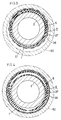
- Fig. 3 shows the shaft 1 of the invention as it is merely inserted in the hollow portion 51 of a core 50 before a fluid is introduced into the elastic tube 5, with a large clearance formed within the hollow portion 51 of the core 50 around the shaft 1.
- Each of the journals 3, 4 is supported by an unillustrated bearing.
- the joint on the hose connected to the pressure fluid source is joined to the joint 31 as already stated to apply fluid pressure to the tube 5.
- compressed air is used as the pressure fluid, helium gas or other gas, or a liquid such as water or oil is alternatively usable.
- the tube 5 When the pressure fluid is introduced into the elastic tube 5, the tube 5 is inflated to increase the outside diameter of the helical winding 5a thereof, causing the protective cover 6 to intimately contact the inner surface of the core 50 defining the hollow portion 51 as seen in Fig. 4.
- the valve of the joint 31 automatically closes to hold the tube 5 inflated.
- the valve 30 of the joint 31 is pushed in from outside against the force of spring, whereupon the valve 30 is opened to release the fluid pressure from the tube 5 via the fluid channels 22, 23 and the valve opening.
- the shaft 1 is connected to a brake device when the core 50 is used for unwinding.
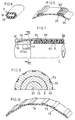
- the tubular protective cover 6 protects the helical tube winding 5a. With an increase in the outside diameter of the helical winding 5a when the tube 5 is inflated, the protective cover 6 similarly increases in diameter and comes into intimate contact with the inner surface of the core 50, so that the cover 6 also serves to perfectly join the shaft 1 to the core 50. Since the multiplicity of strips 37 of the protective cover 6 are made of a harder material than the elastic sleeve 36, the strips 37 permit the cover 6 to retain its shape, rendering the shaft 1 smoothly insertable into or removable from the core hollow portion 51. For this purpose, the strip 37 is preferably formed on its outer surface with a plurality of ridges 52 extending longitudinally thereof as seen in Fig. 6.
- Figs. 7 and 8 show another core shaft embodying the invention.
- the tube 5 of this embodiment has a flexible linear member 53 extending therethrough over its entire length and useful for winding the tube 5 helically and holding the tube in shape.
- the linear member 53 although inserted through the tube 5, may alternatively be embedded in the wall of the tube 5.
- a copper wire is used as the flexible linear member 53, other metal wire such as an aluminum wire is also usable.
- a polyamide yarn, polyester yarn or like yarn is similarly usable.
- a protective cover 54 comprises an elastic sleeve 55, and a multiplicity of strips 56 each in the form of an elongated metal plate, adhered to the outer surface of the sleeve 55, extending axially thereof and arranged at a spacing circumferentially thereof.
- each strip 56 is resilient. In reverse relation to the first embodiment, each strip 56 projects at its opposite ends beyond the respective ends of the elastic sleeve 55.
- Each of support rings 40, 41 is formed in the upper surface of its inner end with a step 77, around which the end of the sleeve 55 is fitted.
- Formed in each of tapered outer peripheral surfaces 44, 45 of these support rings 40, 41 are grooves 76 having fitted therein the projections 75 of the strips 56 at the end of each, the projections 75 being movable when the tube 5 is inflated.
- the second embodiment is the same as the first.
- Figs. 9 and 10 show another core shaft embodying the invention.
- This embodiment has an elastic tube 57 which is circular in cross section and is helically wound as at 57a.
- a support ring 58 is secured to the shaft body 2 at each side of the winding 57a.
- a protective cover 59 is fitted at its opposite ends around the support rings 58.
- the cover 59 is in the form of a sleeve which is axially cut at one portion and is made of such a material that it is deformable to a larger diameter but can restore itself.
- the cover 59 of this embodiment is made of polycarbonate, also usable for the cover are other materials such as polyvinyl chloride resin, polyamide, polyethylene, iron and stainless steel.
- Each open end of the shaft body 2 is internally threaded and has screwed therein an externally threaded portion 61 of a journal 60 at its inner end.
- a hexagonal flange 62 formed on the journal 60 at the outer end of the threaded portion 61 bears against the end face of the shaft body 2.
- the tube 57 has a nonhelical portion 57b which is secured by a fastener 64 to a flat portion 63 of the circular support ring 58 and which extends into the hollow portion 9 of the shaft body 2 through a hole 65 in the shaft body peripheral wall.
- the journal 60 has a fluid channel 66 extending centrally therethrough.
- a hollow connector 67 inserted in the channel 66 as attached to the journal inner end has a spigot 68, to which the open left end of the tube 57 is fastened with bands 69.
- the outer end of the fluid channel 66 is provided with a joint 31 having an automatic shutoff valve 30.
- Each nonhelical portion 57b of the tube 57 is covered with a nonstretchable member 70.
- the nonstretchable member 70 is closely wound around the nonhelical portion 57b, whereby the tube 57 is prevented from inflation at this portion.
- the nonstretchable member may alternatively be a metal wire which is closely wound on the nonhelical portion, or a thermally shrinkable synthetic resin tube which is thermally shrunk as fitted around the nonhelical portion.
- the outer peripheral surface of the shaft body 2 may be formed with a shallow helical groove 71 for guiding the elastic tube 57 when it is wound on the body 2.
- Fig. 12 shows a protective cover 72 in the form of a tube which comprises a multiplicity of stretchable portions 73 and a multiplicity of non-stretchable portions 74 extending longitudinally of the cover and arranged alternately circumferentially thereof.
- the stretchable portions 73 can be made of thermoplastic polyurethane elastomer, thermoplastic polyester elastomer, polyvinyl chloride resin, polyurethane resin or the like. It is suitable to prepare the nonstretchable portions 74 from polypropylene.
- the stretchable portions 73 and the nonstretchable portions 74 are formed integrally by two-color extrusion.
Claims (19)
Applications Claiming Priority (4)
| Application Number | Priority Date | Filing Date | Title |
|---|---|---|---|
| JP33520587A JPH01176755A (ja) | 1987-12-28 | 1987-12-28 | 巻芯用シャフト |
| JP335205/87 | 1987-12-28 | ||
| JP335206/87 | 1987-12-28 | ||
| JP62335206A JPH0739303B2 (ja) | 1987-12-28 | 1987-12-28 | 巻芯用シャフト |
Publications (2)
| Publication Number | Publication Date |
|---|---|
| EP0322864A1 EP0322864A1 (de) | 1989-07-05 |
| EP0322864B1 true EP0322864B1 (de) | 1992-03-11 |
Family
ID=26575095
Family Applications (1)
| Application Number | Title | Priority Date | Filing Date |
|---|---|---|---|
| EP88121729A Expired EP0322864B1 (de) | 1987-12-28 | 1988-12-27 | Spindel für eine Wickelhülse |
Country Status (2)
| Country | Link |
|---|---|
| EP (1) | EP0322864B1 (de) |
| DE (1) | DE3869100D1 (de) |
Families Citing this family (2)
| Publication number | Priority date | Publication date | Assignee | Title |
|---|---|---|---|---|
| IT1395993B1 (it) * | 2009-08-03 | 2012-11-09 | Perini Fabio Spa | "mandrino di avvolgimento per la produzione di rotoli di materiale nastriforme" |
| US20240327165A1 (en) * | 2023-03-29 | 2024-10-03 | Goldenrod Corporation | Double tube composite winding shaft |
Family Cites Families (12)
| Publication number | Priority date | Publication date | Assignee | Title |
|---|---|---|---|---|
| CA653299A (en) * | 1962-12-04 | The B. F. Goodrich Company | Expansible mandrel assembly | |
| CA654990A (en) * | 1963-01-01 | Canadian General Electric Company | Inflatable mandrel | |
| AT284427B (de) * | 1966-11-16 | 1970-09-10 | Rudolf Ing Schuetz | Wickelwelle für Folien-, Papier- und Textilbahnen |
| US3425642A (en) * | 1966-12-12 | 1969-02-04 | Goodrich Co B F | Inflatable mandrel |
| DE2041860A1 (de) * | 1970-08-24 | 1972-03-02 | Brahm Walter Im | Spannhuelse fuer Haspeldorn mit kontinuierlich veraenderlicher,geschlossener Umlaufflaeche |
| DE2218561C3 (de) * | 1972-04-17 | 1978-04-27 | Uniroyal Ag, 5100 Aachen | Aufnahmedorn für Vorrichtungen zum Abstechen von Ringen von eine undehnbare Einlage aufweisenden Schläuchen oder Rohren aus Gummi, Kunststoff oder ähnlichem Material |
| US3825167A (en) * | 1972-12-26 | 1974-07-23 | A Komorek | Expanding mandrel or chuck |
| US3917187A (en) * | 1974-07-12 | 1975-11-04 | Lawrence R Damour | Expanding mandrel or chuck |
| US3937412A (en) * | 1975-04-23 | 1976-02-10 | Damour Lawrence R | Expanding outer sleeve for a mandrel or chuck |
| DE8004622U1 (de) * | 1980-02-21 | 1980-06-04 | Th. Goldschmidt Ag, 4300 Essen | Spannvorrichtung |
| DE3134146C2 (de) * | 1981-08-28 | 1984-09-13 | Hans Lenze & Co KG, 3251 Aerzen | Spannwelle für Wickelhülsen |
| US4632328A (en) * | 1985-07-25 | 1986-12-30 | The B. F. Goodrich Company | Inflatable mandrel and method therefor |
-
1988
- 1988-12-27 EP EP88121729A patent/EP0322864B1/de not_active Expired
- 1988-12-27 DE DE8888121729T patent/DE3869100D1/de not_active Expired - Lifetime
Also Published As
| Publication number | Publication date |
|---|---|
| DE3869100D1 (de) | 1992-04-16 |
| EP0322864A1 (de) | 1989-07-05 |
Similar Documents
| Publication | Publication Date | Title |
|---|---|---|
| US4135677A (en) | Pneumatic shafts, chucks and lifts for roll stock | |
| US4599784A (en) | Method of assembling flexible conduit and fitting | |
| AU594748B2 (en) | Pump block for interfacing irradiation chamber to photoactivation patient treatment system | |
| US4383555A (en) | Helically wound hose from co-extruded profile with reinforcing ribs interlocked at adjacent convolutions | |
| US4114909A (en) | Core locking device | |
| US6223648B1 (en) | Artificial muscle actuator assembly | |
| US5445342A (en) | Expansible shaft for roll core | |
| CA1326870C (en) | Self-tightening soft tubing fitting and method | |
| US5148836A (en) | Flexible hose construction | |
| CA1238260A (en) | Pressure cylinder | |
| US3053467A (en) | Expansible shaft | |
| US5349988A (en) | Corregated refrigeration hose system | |
| US4451070A (en) | Hose coupling | |
| US4895550A (en) | Blow-molded convoluted boot | |
| GB2258019A (en) | Mechanical face seals | |
| IT7354556A1 (it) | Perfezionamento nei mandrini ad espansione. | |
| US4324511A (en) | Carrier for pneumatic tube systems | |
| EP0872664A3 (de) | Klemmvorrichtung für pneumatisches Stellelement | |
| EP1118809A2 (de) | Schraubenförmig gewickelter Schlauch | |
| HU226854B1 (en) | Hoses or flexible pipes | |
| US3982649A (en) | Bung for a barrel | |
| EP0322864A1 (de) | Spindel für eine Wickelhülse | |
| CA1108667A (en) | Hose coupling joint | |
| JPH04262177A (ja) | ダイヤフラムバルブ | |
| EP1599688B1 (de) | Muffe mit o-ring-dichtung |
Legal Events
| Date | Code | Title | Description |
|---|---|---|---|
| PUAI | Public reference made under article 153(3) epc to a published international application that has entered the european phase |
Free format text: ORIGINAL CODE: 0009012 |
|
| AK | Designated contracting states |
Kind code of ref document: A1 Designated state(s): BE DE FR GB IT |
|
| 17P | Request for examination filed |
Effective date: 19891201 |
|
| 17Q | First examination report despatched |
Effective date: 19901004 |
|
| GRAA | (expected) grant |
Free format text: ORIGINAL CODE: 0009210 |
|
| AK | Designated contracting states |
Kind code of ref document: B1 Designated state(s): BE DE FR GB IT |
|
| REF | Corresponds to: |
Ref document number: 3869100 Country of ref document: DE Date of ref document: 19920416 |
|
| ET | Fr: translation filed | ||
| ITF | It: translation for a ep patent filed | ||
| PGFP | Annual fee paid to national office [announced via postgrant information from national office to epo] |
Ref country code: GB Payment date: 19921203 Year of fee payment: 5 |
|
| PGFP | Annual fee paid to national office [announced via postgrant information from national office to epo] |
Ref country code: FR Payment date: 19921223 Year of fee payment: 5 |
|
| PGFP | Annual fee paid to national office [announced via postgrant information from national office to epo] |
Ref country code: BE Payment date: 19921229 Year of fee payment: 5 |
|
| PGFP | Annual fee paid to national office [announced via postgrant information from national office to epo] |
Ref country code: DE Payment date: 19921230 Year of fee payment: 5 |
|
| PLBE | No opposition filed within time limit |
Free format text: ORIGINAL CODE: 0009261 |
|
| STAA | Information on the status of an ep patent application or granted ep patent |
Free format text: STATUS: NO OPPOSITION FILED WITHIN TIME LIMIT |
|
| 26N | No opposition filed | ||
| PG25 | Lapsed in a contracting state [announced via postgrant information from national office to epo] |
Ref country code: GB Effective date: 19931227 |
|
| PG25 | Lapsed in a contracting state [announced via postgrant information from national office to epo] |
Ref country code: BE Effective date: 19931231 |
|
| BERE | Be: lapsed |
Owner name: YAMAUCHI CORP. Effective date: 19931231 |
|
| GBPC | Gb: european patent ceased through non-payment of renewal fee |
Effective date: 19931227 |
|
| PG25 | Lapsed in a contracting state [announced via postgrant information from national office to epo] |
Ref country code: FR Effective date: 19940831 |
|
| PG25 | Lapsed in a contracting state [announced via postgrant information from national office to epo] |
Ref country code: DE Effective date: 19940901 |
|
| REG | Reference to a national code |
Ref country code: FR Ref legal event code: ST |
|
| PG25 | Lapsed in a contracting state [announced via postgrant information from national office to epo] |
Ref country code: IT Free format text: LAPSE BECAUSE OF NON-PAYMENT OF DUE FEES Effective date: 20051227 |