EP0323858A2 - Planetenradeinheit für Differential - Google Patents
Planetenradeinheit für Differential Download PDFInfo
- Publication number
- EP0323858A2 EP0323858A2 EP89100266A EP89100266A EP0323858A2 EP 0323858 A2 EP0323858 A2 EP 0323858A2 EP 89100266 A EP89100266 A EP 89100266A EP 89100266 A EP89100266 A EP 89100266A EP 0323858 A2 EP0323858 A2 EP 0323858A2
- Authority
- EP
- European Patent Office
- Prior art keywords
- gear
- ring gear
- planet
- gears
- planet gear
- Prior art date
- Legal status (The legal status is an assumption and is not a legal conclusion. Google has not performed a legal analysis and makes no representation as to the accuracy of the status listed.)
- Granted
Links
- 230000009471 action Effects 0.000 claims abstract description 14
- 230000009467 reduction Effects 0.000 description 15
- 230000005540 biological transmission Effects 0.000 description 12
- 230000015572 biosynthetic process Effects 0.000 description 6
- 230000004048 modification Effects 0.000 description 4
- 238000012986 modification Methods 0.000 description 4
- 238000010276 construction Methods 0.000 description 3
- 230000003247 decreasing effect Effects 0.000 description 2
- 230000003292 diminished effect Effects 0.000 description 2
- 230000000694 effects Effects 0.000 description 2
- 238000005299 abrasion Methods 0.000 description 1
- 230000007547 defect Effects 0.000 description 1
- 230000009699 differential effect Effects 0.000 description 1
- 230000003467 diminishing effect Effects 0.000 description 1
- 230000006872 improvement Effects 0.000 description 1
- 230000007246 mechanism Effects 0.000 description 1
- 238000005096 rolling process Methods 0.000 description 1
Images



Classifications
-
- F—MECHANICAL ENGINEERING; LIGHTING; HEATING; WEAPONS; BLASTING
- F16—ENGINEERING ELEMENTS AND UNITS; GENERAL MEASURES FOR PRODUCING AND MAINTAINING EFFECTIVE FUNCTIONING OF MACHINES OR INSTALLATIONS; THERMAL INSULATION IN GENERAL
- F16H—GEARING
- F16H1/00—Toothed gearings for conveying rotary motion
- F16H1/28—Toothed gearings for conveying rotary motion with gears having orbital motion
- F16H1/46—Systems consisting of a plurality of gear trains each with orbital gears, i.e. systems having three or more central gears
-
- F—MECHANICAL ENGINEERING; LIGHTING; HEATING; WEAPONS; BLASTING
- F16—ENGINEERING ELEMENTS AND UNITS; GENERAL MEASURES FOR PRODUCING AND MAINTAINING EFFECTIVE FUNCTIONING OF MACHINES OR INSTALLATIONS; THERMAL INSULATION IN GENERAL
- F16H—GEARING
- F16H55/00—Elements with teeth or friction surfaces for conveying motion; Worms, pulleys or sheaves for gearing mechanisms
- F16H55/02—Toothed members; Worms
- F16H55/08—Profiling
- F16H55/0806—Involute profile
-
- F—MECHANICAL ENGINEERING; LIGHTING; HEATING; WEAPONS; BLASTING
- F16—ENGINEERING ELEMENTS AND UNITS; GENERAL MEASURES FOR PRODUCING AND MAINTAINING EFFECTIVE FUNCTIONING OF MACHINES OR INSTALLATIONS; THERMAL INSULATION IN GENERAL
- F16H—GEARING
- F16H1/00—Toothed gearings for conveying rotary motion
- F16H1/28—Toothed gearings for conveying rotary motion with gears having orbital motion
- F16H2001/2881—Toothed gearings for conveying rotary motion with gears having orbital motion comprising two axially spaced central gears, i.e. ring or sun gear, engaged by at least one common orbital gear wherein one of the central gears is forming the output
-
- Y—GENERAL TAGGING OF NEW TECHNOLOGICAL DEVELOPMENTS; GENERAL TAGGING OF CROSS-SECTIONAL TECHNOLOGIES SPANNING OVER SEVERAL SECTIONS OF THE IPC; TECHNICAL SUBJECTS COVERED BY FORMER USPC CROSS-REFERENCE ART COLLECTIONS [XRACs] AND DIGESTS
- Y10—TECHNICAL SUBJECTS COVERED BY FORMER USPC
- Y10T—TECHNICAL SUBJECTS COVERED BY FORMER US CLASSIFICATION
- Y10T74/00—Machine element or mechanism
- Y10T74/19—Gearing
- Y10T74/19949—Teeth
- Y10T74/19963—Spur
- Y10T74/19972—Spur form
Definitions
- the present invention relates to a differential planet gear unit for use in reduction gears constituting link driving mechanisms for industrial robots.
- each of these robots is provided with reduction gears for reducing the rotational speed of each actuator.
- this kind of reduction gears a large reduction gear ratio as well as small in size and light in weight is required.
- reduction gears having a high torque and power transmission with a high torsion rigidity are also required.
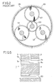
- a conventional differential planet gear unit 100 as shown in Figs. 1 and 2, has been used as a reduction gear.
- a sun gear 103 is rotated by the rotation of an input shaft 101, and the rotation of the sun gear 103 is transmitted to three planet gears 107 arranged at an equal angular distance so as to engage with both the sun gear 103 and a fixed ring gear 105.
- the planet gears 107 rotate around their own axes while they also revolve around the sun gear 103.
- Each of the planet gears 107 is engaged with the fixed ring gear 105 as well as with a rotary ring gear 109 having a slight difference in the number of teeth relative to that of the fixed ring gear 105, thereby rotating an output shaft 111 through the rotary ring gear 109 secured thereto.
- the addendum modification coefficient of one ring gear having the less number of teeth for instance, the fixed ring gear 105 is formed large in its design.
- the diameter of the addendum circle 105a of the fixed ring gear 105 is almost equal to that of the addendum circle 109a of the rotary ring gear 109 in its size.
- the planet gears 107 engaging with both the ring gears 105 and 109 are integrally formed and have a common formation so that the diameter of the addendum circle 107a of the planet gear 107, which contacts with both the fixed and rotary ring gears 105 and 109, is equal to those of the latter.
- the inventor of this application has been found the reason or cause of the low power transmission efficiency after conducting various experiments for the differential planet gear unit.
- the efficiency of the differential planet gear unit 100 can be sought from the ratio of contact of the gears in the unit 100. Particularly, each of the ratios of contact between the fixed ring gear 105 and the planet gear 107 and between the rotary ring gear 109 and the planet gear 107 gives much affection to the power transmission efficiency.
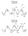
- Fig. 4(a) shows the involute tooth forms of the fixed ring gear 105 and the planet gear 107 and a contact action line l1 thereof in the gear unit 100. Since the addendum modification coefficient of the fixed ring gear 105 is very large as compared with that of the planet gear 107, a contact pitch point Pc largely leans toward the addendum from the center of the tooth height of the planet gear 107. As a result, it is to be appreciated that an approaching contact length e1, i.e. a straight line segment A - Pc between a contact start point A and the contact pitch point Pc is short while a receding contact length e2, i.e. a straight line segment Pc - B between the contact pitch point Pc and a contact end point B is much long.
- e1 i.e. a straight line segment A - Pc between a contact start point A and the contact pitch point Pc
- a receding contact length e2 i.e. a straight line segment P
- Fig. 4(b) shows the involute tooth forms of the rotary ring gear 109 and the planet gear 107 and a contact action line l2 thereof.
- a contact pitch point Pd largely leans toward the dedendum from the center of the tooth height of the planet gear 107. Consequently, it is appreciated that the approaching contact length e1, i.e., A - Pd is short whereas the receding contact length e2, i.e., Pd - B is much long.
- a differential planet gear unit comprising a sun gear, planet gears engaged with the sun gear, a first ring gear having a first number of teeth, and a second ring gear having a second number of teeth, the first tooth number being different from the second tooth number, the first and second ring gears coaxially aligning and simultaneously engaging with first and second tooth portions of each planet gear, respectively, diameters of addendum circles of the teeth of the first ring gear and the first tooth portion of each planet gear being different from those of the second ring gear and the second tooth portion of each planet gear, respectively, to reduce a difference between an approaching contact length and a receding contact length along a contact action line of each of the planet gears and one of the first and second ring gears.
- a differential planet gear unit comprising a sun gear, planet gears engaged with the sun gear, a first ring gear having a first number of teeth, and a second ring gear having a second number of teeth, the first tooth number being different from the second tooth number, the first and second ring gears coaxially aligning and simultaneously engaging with first and second tooth portions of each planet gear, respectively, the first ring gear being formed with first chamfers in both sides of addendum of the teeth and the second tooth portion of each planet gear being formed with second chamfers in both sides of addendum of the teeth to reduce a difference between an approaching contact length and a receding contact length along a contact action line of each of the planet gear and one of the first and second ring gears.
- a differential planet gear unit having basically the same construction as that of the conventional differential planet gear unit shown in Figs. 1 to 4, except tooth forms of gears, and thus the description of the same portions as those of the conventional differential planet gear unit may be omitted for the brevity.
- the differential planet gear unit 1 comprises a sun gear 103 at its center, two ring gears consisting of a fixed ring gear 5 and a rotary ring gear 9 which have the difference in the number of teeth, respectively, engaged with the sun gear 103 coaxially, and planet gears 7 provided around the sun gear 103 so as to engage with both the fixed ring gear 5 and the rotary ring gear 9 as well as the sun gear 103.
- the ratios of contact of the ring gears is large, but approximately 1.2 to 1.4 may be sufficient as the ratio of contact in this embodiment.
- diameters of addendum circles of fixed and rotary ring gears are improved so that the diameter of the addendum circle of one having a smaller tooth number may be enlarged while the diameter of the addendum circle of the other having a larger tooth number may be diminished.
- the diameters of the addendum circles of both the fixed ring gear 5 and the rotary ring gear 9 are so formed that the diameter of the addendum circle 9a of the rotary ring gear 9 having the much number of teeth is 132.48 mm which is substantially the same value as that of the conventional one, while the diameter of the addendum circle 5a of the fixed ring gear 5 having the less number of teeth is 133.63 mm which is larger than that of the conventional one. Namely, the former is larger than the latter in diameter.
- the enlarging and diminishing of the diameters of the addendum circles of the fixed and rotary ring gears may be properly modified in practice, as occasion demands.
- the diameter of the addendum circle of the planet gear 107 in the conventional gear unit is 61.9 mm
- the diameter of the addendum circle 7a of the planet gear 7 engaging with the fixed ring gear 5 is enlarged to 62.40 mm while the diameter of the addendum circle 8a of the planet gear 7 engaging with the rotary ring gear 9 is reduced to 60.34 mm.
- the latter is formed smaller than the former in diameter.
- the addendum circle of the fixed ring gear 5 is formed large and one of the addendum circle 8a of the planet gear 7 is formed large, while the other 7a thereof is formed small in its construction.
- Table 1 One embodiment of the formation of the gears of the differential planer gear unit of the present invention is tabulated in Table 1.
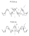
- Fig. 6 there is shown a first embodiment of the present invention
- Figs. 6(a) and (b) show respectively the contact lengths in the diameters of the addendum circles of the planet gear 7 and the fixed or rotary ring gear 5 or 9 of the differential planet gear unit according to the present invention.
- the addendum circle 5a of the fixed ring gear 5 is formed much larger than that of the conventional one shown in Fig. 4a by somewhat enlarging the addendum circle 7a of the planet gear 7 in order to ensure the necessary ratio of contact.
- a contact start point A′ is much away from the contact pitch point Pc than the conventional contact start point A, and a contact end point B′ is much closer toward the contact pitch point Pc than the conventional contact end point B.
- the contact section B - B′ where the sliding velocity is increased due to the offset from the pitch Pc can be removed in this embodiment, thereby improving the contact efficiency.
- Fig. 7 there is shown a second embodiment of the present invention
- Fig. 7(a) and (b) show respectively the contact lengths in the diameters of the addendum circules of the planet gear 7 and the fixed or rotary ring gear 5 or 9 of the differential planet gear unit according to the present invention, in which the sides of the addendum of the teeth of the fixed ring gear 5 and the engage portion 8a of the planet gear 7 are chamfered, with the result of the same effect and advantages as those obtaines in the first embodiment described above.
- the fixed ring gear 5 having the same diameter of the addendum circut 5a as that of the conventional one is formed with chamfers 15 in its both sides of the addendum of the teeth of the gear by chamfering.
- chamfers 17 are provided in both sides of the addendum of the teeth of engage portion 8a engaging with the rotary ring gear 9.
- the contact end point B′ is much closer to the pitch point Pc or Pd than the conventional end point B, thereby improving the contact efficiency in the similar manner to the first embodiment.
- Fig. 8 shows the characteristic curves of the improved ratios of contact in the foregoing embodiments according to the present invention.
- the X-axis indicates the ratio e1/e2 or e2/e1 between the approaching ratio of contact e1 and the receding ratio of contact e2, while the Y-axis indicates the ratio of contact e0 .
- each gear is expressed by P - Q and P - R, where P indicates the planet gear 7, Q indicates the fixed ring gear 5, and R indicates the rotary ring gear 9.
- the ones indicated by the solid lines show the relationship between e0 and e1/e2 or between e0 and e2/e1, when the total ratio of contact e is varied from 1.0 to 1.8.
- ⁇ i 1 - ⁇ . ⁇ (1/Z2 - 1/Z1)e0
- ⁇ is an average abrasion coefficient of contact
- Z1 the number of teeth of an outernal gear
- Z2 the number of teeth of an ring gear.
- the ratio of contact e0 can strikingly be lowered by the stepping difference after correction, thereby improving the power transmission efficiency largely.
- the power transmission efficiency of the differential planet gear unit according to the present invention can be improved up to 80 to 85% by the above improvement in the ratio of contract in each gear, which will largely affect the power transmission efficiency of the gear unit, compared with the conventional one. Yet, a high efficiency can be realized without lowering the merit of the differential planet gear unit of this kind, such as small in size, light in weight, high reduction in speed, and high rigidity. In addition, the contact noise generated by the gear engagement can be reduced in the gear unit according to the present invention.
- the present invention is not limited to the embodiments described above.
- the difference in the number of teeth of the fixed and rotary ring gears may be determined, other than the ones described in the foregoing embodiments. In that case, the effects of the differential planet gear unit are not changed even when the number of teeth of the fixed ring gear is much increased than that of the rotary ring gear.
- a tooth formation of the gears is also not limited to the sizes described in the embodiments according to the present invention.
- the diameter of the addendum circle of each gear is not limited to the sizes described in the foregoing embodiment only when the relationship of the sizes of the gears is maintained at the gist of the invention.
- the present invention can be applied to other differential planet gear units without the sun gear, or having a different number of the planet gears.
- differential planet gear unit has been applied to reduction gears in the foregoing embodiments, it is also possible that the same can be applied to speed-up gears with the input and output shafts being reversed.
Landscapes
- Engineering & Computer Science (AREA)
- General Engineering & Computer Science (AREA)
- Mechanical Engineering (AREA)
- Retarders (AREA)
- Gears, Cams (AREA)
Applications Claiming Priority (2)
| Application Number | Priority Date | Filing Date | Title |
|---|---|---|---|
| JP404/88 | 1988-01-06 | ||
| JP63000404A JP2575435B2 (ja) | 1988-01-06 | 1988-01-06 | 差動遊星歯車装置 |
Publications (3)
| Publication Number | Publication Date |
|---|---|
| EP0323858A2 true EP0323858A2 (de) | 1989-07-12 |
| EP0323858A3 EP0323858A3 (en) | 1990-03-28 |
| EP0323858B1 EP0323858B1 (de) | 1993-05-12 |
Family
ID=11472863
Family Applications (1)
| Application Number | Title | Priority Date | Filing Date |
|---|---|---|---|
| EP89100266A Expired - Lifetime EP0323858B1 (de) | 1988-01-06 | 1989-01-09 | Planetenradeinheit für Differential |
Country Status (4)
| Country | Link |
|---|---|
| US (1) | US4942781A (de) |
| EP (1) | EP0323858B1 (de) |
| JP (1) | JP2575435B2 (de) |
| DE (1) | DE68906401T2 (de) |
Cited By (4)
| Publication number | Priority date | Publication date | Assignee | Title |
|---|---|---|---|---|
| DE4026886A1 (de) * | 1990-08-25 | 1992-02-27 | Renk Ag | Planetengetriebe |
| DE19632103A1 (de) * | 1995-08-10 | 1997-02-13 | Samsung Electronics Co Ltd | Eingriffstörungsverhinderungszahnrad für Kommunikationsvorrichtungen und elektrische Geräte |
| DE19860164A1 (de) * | 1998-12-24 | 2000-07-27 | Hubert Biehler | Verstelleinrichtung zur Drehverstellung, insbesondere für einen Sitz eines Kraftfahrzeuges |
| US6632154B2 (en) * | 2000-01-21 | 2003-10-14 | Seiko Epson Corporation | Gear apparatus |
Families Citing this family (35)
| Publication number | Priority date | Publication date | Assignee | Title |
|---|---|---|---|---|
| US5245851A (en) * | 1989-09-19 | 1993-09-21 | M.H. Center Limited | Differential pinion, metal mold for plastic working the same, and method for plastic working with the metal mold |
| JPH03239841A (ja) * | 1990-02-14 | 1991-10-25 | Mitsubishi Electric Corp | 遊星歯車装置 |
| JP3175240B2 (ja) * | 1990-11-14 | 2001-06-11 | セイコーエプソン株式会社 | 小型減速機 |
| DE4217784C2 (de) * | 1991-06-12 | 1994-02-17 | Viscodrive Gmbh | Differentialgetriebe |
| JP3387935B2 (ja) * | 1991-07-08 | 2003-03-17 | 株式会社東芝 | 遊星歯車装置 |
| US5310389A (en) * | 1992-11-17 | 1994-05-10 | Zexel-Gleason Usa, Inc. | Parallel-axis differential gear tooth modification |
| US5704864A (en) * | 1993-12-27 | 1998-01-06 | Yugen Kaisha Sozoan | Drive unit |
| DE4446115A1 (de) * | 1993-12-27 | 1995-06-29 | Yugen Kaisha Sozoan Matsumoto | Geschwindigkeitswandler |
| JP3202503B2 (ja) * | 1994-10-14 | 2001-08-27 | 栃木富士産業株式会社 | デファレンシャル装置 |
| US5655987A (en) * | 1995-06-20 | 1997-08-12 | Zexel Torsen Inc. | Roll-formed differential gear |
| JP4524012B2 (ja) * | 1999-09-27 | 2010-08-11 | シチズンマイクロ株式会社 | 小型遊星歯車装置 |
| TW459937U (en) * | 2000-02-18 | 2001-10-11 | Wei A Jin | Planet-type gear shift device |
| US6626792B2 (en) * | 2000-03-07 | 2003-09-30 | The United States Of America As Represented By The Administrator Of The National Aeronautics And Space Administration | Gear bearings |
| WO2002064397A1 (de) * | 2001-02-12 | 2002-08-22 | Volkswagen Aktiengesellschaft | Verstelleinrichtung zur drehverstellung zweier zentrisch gelagerter adapterstücke, insbesondere für einen sitz vorzugsweise eines kraftfahrzeuges, und planetengetriebe hierfür |
| US20040049925A1 (en) * | 2002-09-12 | 2004-03-18 | Electrolux Home Products, Inc. | Pole pruner |
| US6783478B2 (en) | 2002-09-13 | 2004-08-31 | Moog Inc. | Compound differential planetary gear assembly |
| JP2004324736A (ja) * | 2003-04-23 | 2004-11-18 | Toyoda Mach Works Ltd | 遊星歯車機構を備えた車輌用差動歯車装置およびその製造方法 |
| US20070078038A1 (en) * | 2004-07-20 | 2007-04-05 | Teruhisa Ando | Gear mechanism and reduction planetary gear |
| US20060122027A1 (en) * | 2004-12-03 | 2006-06-08 | Dalenberg Scott R | Automatic transmission and gear train |
| JP4936052B2 (ja) * | 2006-09-25 | 2012-05-23 | 株式会社ジェイテクト | 車両用操舵装置 |
| US8834316B2 (en) * | 2007-11-30 | 2014-09-16 | Bvr Technologies | High ratio gear reducer |
| US8591367B2 (en) * | 2010-02-17 | 2013-11-26 | Stephen John Kochan | Non-backdrivable gear system |
| JP5700743B2 (ja) * | 2010-12-09 | 2015-04-15 | 孝 松田 | かみあい中,すべり率の正負が変化せず、歯元幅を大きく,さらに,かみあい点における歯形の相対曲率を小さくするピッチ円外インボリュート歯形内歯車対 |
| DE102011009600B3 (de) * | 2011-01-27 | 2012-03-15 | Kathrein-Werke Kg | Mobilfunkantenne mit Multi-Strahlformeinrichtung |
| ES2587596T3 (es) * | 2011-08-24 | 2016-10-25 | Zf Wind Power Antwerpen Nv | Sistema de transmisión por engranajes |
| DE102011089021A1 (de) * | 2011-12-19 | 2013-06-20 | Zf Friedrichshafen Ag | Getriebevorrichtung mit einem innenverzahnten Hohlrad sowie zwei damit kämmenden Stirnrädern |
| JP6084876B2 (ja) * | 2013-03-29 | 2017-02-22 | 日本電産サンキョー株式会社 | 蓋体駆動装置 |
| CN104214311B (zh) * | 2014-09-24 | 2016-09-14 | 南车戚墅堰机车车辆工艺研究所有限公司 | 花键齿轮传动装置 |
| US11266270B2 (en) * | 2017-05-23 | 2022-03-08 | Vita-Mix Management Corporation | Food processor assembly for a blender base |
| CN107461460A (zh) * | 2017-09-11 | 2017-12-12 | 马墉良 | 改进型分度圆差减速装置 |
| CN108087517B (zh) * | 2018-01-26 | 2022-03-22 | 柳州市怀远数控技术开发有限公司 | 一种细分微分差动减速器 |
| JP7417360B2 (ja) * | 2019-03-11 | 2024-01-18 | 住友重機械工業株式会社 | 歯車装置 |
| US11903523B2 (en) | 2019-07-22 | 2024-02-20 | Vita-Mix Management Corporation | Food processor assembly |
| US11473664B2 (en) * | 2019-10-21 | 2022-10-18 | Aktiebolaget Skf | Gear tooth chamfer for an annular gear |
| US11877696B2 (en) | 2019-12-19 | 2024-01-23 | Vita-Mix Management Corporation | Food processor |
Family Cites Families (16)
| Publication number | Priority date | Publication date | Assignee | Title |
|---|---|---|---|---|
| FR968247A (fr) * | 1948-06-21 | 1950-11-22 | Réducteur de vitesse | |
| DE821302C (de) * | 1948-12-04 | 1951-11-15 | Wilhelm Stoeckicht Dipl Ing | Differential-Untersetzungsgetriebe |
| US2682760A (en) * | 1950-04-18 | 1954-07-06 | American Flexible Coupling Com | Gear coupling |
| FR1086343A (fr) * | 1953-07-08 | 1955-02-11 | Signaux Entr Electriques | Réducteur de vitesse |
| FR1257265A (fr) * | 1960-03-23 | 1961-03-31 | Réducteur de vitesse différentiel | |
| US3116651A (en) * | 1961-03-21 | 1964-01-07 | Gen Motors Corp | Gearing |
| GB1085291A (en) * | 1964-09-17 | 1967-09-27 | Vauxhall Motors Ltd | Noise reduction of toothed gears |
| US3596538A (en) * | 1968-12-05 | 1971-08-03 | Arthur R Braun | Speed changing device |
| US3792629A (en) * | 1971-12-30 | 1974-02-19 | Mc Donnell Douglas Corp | Speed reducer with ring and planet gears having different circular pitches |
| US4043226A (en) * | 1974-09-30 | 1977-08-23 | Fairfield Manufacturing Company, Inc. | Disengage mechanism for gear drive |
| SE409497B (sv) * | 1978-10-02 | 1979-08-20 | Jonsson Sven | Kuggvexel jemte forfaringssett och apparat for dess framstellning |
| US4280376A (en) * | 1979-05-17 | 1981-07-28 | Energistics, Inc. | Planetary gear system and gears therefore |
| GB2153957B (en) * | 1984-02-09 | 1986-11-26 | Warner Lambert Tech | Endoscope |
| US4679459A (en) * | 1986-04-22 | 1987-07-14 | The United States Of America As Represented By The Secretary Of The Army | Concave-convex gear pair having staggered teeth |
| FR2598766B1 (fr) * | 1986-05-14 | 1991-05-03 | Mijno Fils Ets J | Reducteur de vitesse a train epicycloidal |
| IT1201114B (it) * | 1987-01-08 | 1989-01-27 | Comer Spa | Variatore di giri ad ingranaggi a costruzione semplificata |
-
1988
- 1988-01-06 JP JP63000404A patent/JP2575435B2/ja not_active Expired - Lifetime
-
1989
- 1989-01-06 US US07/294,019 patent/US4942781A/en not_active Expired - Lifetime
- 1989-01-09 DE DE89100266T patent/DE68906401T2/de not_active Expired - Lifetime
- 1989-01-09 EP EP89100266A patent/EP0323858B1/de not_active Expired - Lifetime
Cited By (7)
| Publication number | Priority date | Publication date | Assignee | Title |
|---|---|---|---|---|
| DE4026886A1 (de) * | 1990-08-25 | 1992-02-27 | Renk Ag | Planetengetriebe |
| DE19632103A1 (de) * | 1995-08-10 | 1997-02-13 | Samsung Electronics Co Ltd | Eingriffstörungsverhinderungszahnrad für Kommunikationsvorrichtungen und elektrische Geräte |
| GB2304169A (en) * | 1995-08-10 | 1997-03-12 | Samsung Electronics Co Ltd | Gear Mechanisms |
| GB2304169B (en) * | 1995-08-10 | 1997-07-09 | Samsung Electronics Co Ltd | Gear mechanisms |
| DE19632103C2 (de) * | 1995-08-10 | 2003-07-31 | Samsung Electronics Co Ltd | Zahnradgetriebe für Kommunikationsvorrichtungen und elektrische Geräte |
| DE19860164A1 (de) * | 1998-12-24 | 2000-07-27 | Hubert Biehler | Verstelleinrichtung zur Drehverstellung, insbesondere für einen Sitz eines Kraftfahrzeuges |
| US6632154B2 (en) * | 2000-01-21 | 2003-10-14 | Seiko Epson Corporation | Gear apparatus |
Also Published As
| Publication number | Publication date |
|---|---|
| DE68906401D1 (en) | 1993-06-17 |
| EP0323858A3 (en) | 1990-03-28 |
| DE68906401T2 (de) | 1993-11-11 |
| JP2575435B2 (ja) | 1997-01-22 |
| JPH01176834A (ja) | 1989-07-13 |
| EP0323858B1 (de) | 1993-05-12 |
| US4942781A (en) | 1990-07-24 |
Similar Documents
| Publication | Publication Date | Title |
|---|---|---|
| EP0323858B1 (de) | Planetenradeinheit für Differential | |
| JP3387935B2 (ja) | 遊星歯車装置 | |
| US6148683A (en) | Worm/worm gear transmission | |
| JP7160413B2 (ja) | 完全閉ループ制御を実現できる遊星減速モータ及び多関節ロボット | |
| US5605518A (en) | Planetary gear device | |
| WO1996004493A1 (en) | Gear system | |
| TW201333347A (zh) | 零背隙之行星式減速機構 | |
| US4850237A (en) | Tooth profile in meshing mechanism | |
| EP1296847B1 (de) | Zahnradantriebe | |
| CN1067152C (zh) | 双点线啮合齿轮 | |
| JP2834286B2 (ja) | インボリュート歯車対および歯車変速機 | |
| US6584867B2 (en) | Spur gear to interconnect rack and worm | |
| EP1626205B1 (de) | Zusammengesetzte planetengetriebevorrichtung | |
| US4372176A (en) | Tapered tooth helical gear drive train for eliminating the need for end thrust bearings | |
| JPH0243619Y2 (de) | ||
| CN110925409A (zh) | 一种行星齿轮弹性消隙减速器 | |
| JP2539907B2 (ja) | 2軸押出機の伝動歯車装置 | |
| EP0161072B1 (de) | Mechanisches Untersetzungsgetriebe | |
| JPH07180749A (ja) | 工作機械用のバックラッシュのない回転付属装置用駆動装置 | |
| CN219169796U (zh) | 一种三段式圆弧滚刀刀具 | |
| JP7706382B2 (ja) | 遊星歯車装置 | |
| EP0770192A1 (de) | Getriebesystem | |
| CN221237118U (zh) | 行星齿轮、传动机构以及动力装置 | |
| JP3237915B2 (ja) | 円錐形インボリュート歯車 | |
| JP2025099734A (ja) | 減速装置 |
Legal Events
| Date | Code | Title | Description |
|---|---|---|---|
| PUAI | Public reference made under article 153(3) epc to a published international application that has entered the european phase |
Free format text: ORIGINAL CODE: 0009012 |
|
| 17P | Request for examination filed |
Effective date: 19890109 |
|
| AK | Designated contracting states |
Kind code of ref document: A2 Designated state(s): DE FR GB SE |
|
| PUAL | Search report despatched |
Free format text: ORIGINAL CODE: 0009013 |
|
| AK | Designated contracting states |
Kind code of ref document: A3 Designated state(s): DE FR GB SE |
|
| 17Q | First examination report despatched |
Effective date: 19910910 |
|
| GRAA | (expected) grant |
Free format text: ORIGINAL CODE: 0009210 |
|
| AK | Designated contracting states |
Kind code of ref document: B1 Designated state(s): DE FR GB SE |
|
| PG25 | Lapsed in a contracting state [announced via postgrant information from national office to epo] |
Ref country code: FR Effective date: 19930512 |
|
| REF | Corresponds to: |
Ref document number: 68906401 Country of ref document: DE Date of ref document: 19930617 |
|
| EN | Fr: translation not filed | ||
| EAL | Se: european patent in force in sweden |
Ref document number: 89100266.9 |
|
| PGFP | Annual fee paid to national office [announced via postgrant information from national office to epo] |
Ref country code: GB Payment date: 19961231 Year of fee payment: 9 |
|
| PG25 | Lapsed in a contracting state [announced via postgrant information from national office to epo] |
Ref country code: GB Free format text: LAPSE BECAUSE OF NON-PAYMENT OF DUE FEES Effective date: 19980109 |
|
| GBPC | Gb: european patent ceased through non-payment of renewal fee |
Effective date: 19980109 |
|
| PGFP | Annual fee paid to national office [announced via postgrant information from national office to epo] |
Ref country code: SE Payment date: 20080104 Year of fee payment: 20 Ref country code: DE Payment date: 20080104 Year of fee payment: 20 |
|
| EUG | Se: european patent has lapsed | ||
| PLBE | No opposition filed within time limit |
Free format text: ORIGINAL CODE: 0009261 |
|
| STAA | Information on the status of an ep patent application or granted ep patent |
Free format text: STATUS: NO OPPOSITION FILED WITHIN TIME LIMIT |