EP0324006B1 - Regelungsverfahren und -vorrichtung mit verschiebung des sollwertes - Google Patents
Regelungsverfahren und -vorrichtung mit verschiebung des sollwertes Download PDFInfo
- Publication number
- EP0324006B1 EP0324006B1 EP88906505A EP88906505A EP0324006B1 EP 0324006 B1 EP0324006 B1 EP 0324006B1 EP 88906505 A EP88906505 A EP 88906505A EP 88906505 A EP88906505 A EP 88906505A EP 0324006 B1 EP0324006 B1 EP 0324006B1
- Authority
- EP
- European Patent Office
- Prior art keywords
- signal
- specification limit
- measured
- set point
- gain
- Prior art date
- Legal status (The legal status is an assumption and is not a legal conclusion. Google has not performed a legal analysis and makes no representation as to the accuracy of the status listed.)
- Expired - Lifetime
Links
- 238000000034 method Methods 0.000 title claims abstract description 69
- 230000010354 integration Effects 0.000 claims abstract 2
- 238000004886 process control Methods 0.000 claims description 7
- 241000269627 Amphiuma means Species 0.000 claims 1
- 238000009826 distribution Methods 0.000 abstract description 27
- 238000005259 measurement Methods 0.000 description 14
- 230000002950 deficient Effects 0.000 description 4
- 238000004364 calculation method Methods 0.000 description 3
- 238000010586 diagram Methods 0.000 description 3
- 238000004519 manufacturing process Methods 0.000 description 3
- 238000005070 sampling Methods 0.000 description 3
- 235000019504 cigarettes Nutrition 0.000 description 2
- 239000000109 continuous material Substances 0.000 description 2
- 239000000463 material Substances 0.000 description 2
- 238000012935 Averaging Methods 0.000 description 1
- 241000208125 Nicotiana Species 0.000 description 1
- 235000002637 Nicotiana tabacum Nutrition 0.000 description 1
- 238000013459 approach Methods 0.000 description 1
- 230000003190 augmentative effect Effects 0.000 description 1
- 238000006243 chemical reaction Methods 0.000 description 1
- 230000001276 controlling effect Effects 0.000 description 1
- 230000007423 decrease Effects 0.000 description 1
- 230000007547 defect Effects 0.000 description 1
- 230000003292 diminished effect Effects 0.000 description 1
- 239000003344 environmental pollutant Substances 0.000 description 1
- 238000009472 formulation Methods 0.000 description 1
- 239000000203 mixture Substances 0.000 description 1
- 238000012986 modification Methods 0.000 description 1
- 230000004048 modification Effects 0.000 description 1
- 231100000719 pollutant Toxicity 0.000 description 1
- 238000000275 quality assurance Methods 0.000 description 1
- 230000001105 regulatory effect Effects 0.000 description 1
- 238000007619 statistical method Methods 0.000 description 1
Images
Classifications
-
- G—PHYSICS
- G05—CONTROLLING; REGULATING
- G05B—CONTROL OR REGULATING SYSTEMS IN GENERAL; FUNCTIONAL ELEMENTS OF SUCH SYSTEMS; MONITORING OR TESTING ARRANGEMENTS FOR SUCH SYSTEMS OR ELEMENTS
- G05B21/00—Systems involving sampling of the variable controlled
- G05B21/02—Systems involving sampling of the variable controlled electric
Definitions
- the present invention relates to a process control apparatus and method for set point control, and in particular to feedback control apparatus and method employing a numerically calculated set point.
- Industrial process controllers are commonly tuned to control an output to meet a particular output specification. Where the features of the system function ideally, setting the control to the ideal specification then produces the specified output with no variation. Material handling systems do not work ideally for numerous reasons, and as a result there is frequently a statistical distribution in the output from the system. Where there is no functional difference between the high side and the low side results of the statistical distribution, setting the control to meet the center of the statistical distribution is a correct choice.
- Prior art document US-A-3 515 860 discloses an apparatus for automatically controlling a continuous material forming process with a controller whose set point is periodically changed or updated in response to a feedback signal from an automatic statistical variance computer, so that when the process variance decreases the controller set point value approaches a selected limiting value and when the variance increases the set point value recedes from the limiting value.
- an auxiliary computer maintains a continually updated running estimate of the next variance value to be expected. When the computed estimate exceeds the previous variance value by a predetermined amount, an alarm is sounded and the set point value is automatically retracted from the limiting value.
- prior art document US-A-3 648 035 describes a system and method for maximizing the profit of a tobacco manufacturing process by computing a measure of the process spread, which can be calculated either in response to standard deviation or fraction defective.
- the average weight of cigarettes manufactured is controlled to maximize profit so that average weight is minimized and variable percentage of the cigarettes weigh less than a limit value.
- prior art document US-A-3 876 872 describes a continuous material production process which is regulated by a controller whose set point is automatically optimized according to statistical computations based on inputs of measured fraction defective and fraction defective set point values. These values are each converted to a linear deviation quantity based on an estimate of standard deviation computed from defect level, process average and measured fraction defective. The deviation quantities and the difference therebetween are computed repeatedly, and the difference values are accumulated to provide integral control of the set point for the process controller.
- Biasing the set point of a controller to the preferred side of a specification limit in relation to the standard deviation of variation in the controlled variable keeps most of the excursions in the controlled variable on the acceptable side of specification limit.
- the specification limit may then be approached as closely as observed variation allows.
- the controlled process may then be maximized for profit or quality by keeping the controlled variable close to the specification limit, but without exceeding the limit.
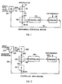
- FIG. 1 shows a schematic diagram of a statistical control process.
- FIG. 2 shows a schematic diagram of a preferred control process.
- FIG. 1 shows a schematic diagram of a control process employing a statistical control process.
- a specification limit 30 is received defining the preferred output condition.
- the specification limit 30 is then augmented or diminished by a bias amount 40 in a summation block 50 depending on whether errors in the process output are preferred on the high side or low side of the specification limit 30.
- the specification limit 30 offset by the bias amount 40 is then the set point 60 for a controller 70.
- the controller 70 affects a process 80 having a measured feature called a measured variable 90.
- the goal of the controller 70 is to bring the process 80 to a state where the measured variable equals the set point 60, or in the present case, where the distribution of the measured variable 90 values is offset on the preferred side of the specification limit 30.
- the set point 60 and measured variable 90 are used to produce a control signal affecting the controller.
- the difference between the set point 60 and the measured variable 90 is computed in a difference block 100 as an error signal 110 used as the control signal.
- the error signal 110 is supplied to the controller 70 to direct the direction and size of the controller's response in affecting the process 80 and correspondingly the measured variable 90.
- the process 80 is sensed to produce the measured variable 90 which is returned to the difference block 100 to generate the error signal 110.
- Applicant additionally supplies the measured variable 90 to a bias calculating block 120.
- the bias calculating block 120 calculates a statistical measure of the distribution in the measured variable 90, for example, the standard deviation. The statistical measure is then appropriately scaled to produce the bias amount 40.
- the standard deviation is a familiar measure.
- To compute the standard deviation of the measured variable 90 an average value of the measured variable 90 is computed for a sample period. The length of the sample period is determined by the user in accordance with the nature of the process 80, the sampling rate of the measured variable 90, and the level of confidence sought. Where the specification limit 30 has a fixed value, and the process 80 is slow moving in comparison to the sampling rate, good statistics may generally be taken under all conditions. Where the distribution is changing, the statistic needs to be normalized by the distribution trend, and compensated for the delay in the process 80.
- the average sample value of the measured variable 90 may be computed as a running average of a number of sample values.
- a number n s is selected by the user which is the number of samples to be averaged.
- the number n s times the sample rate t r gives an effective sample period, which exceeds the closed loop period of the measured signal, and is set to correspond to the capacity of the process 80.
- the sample average, s ave may be computed in several ways.
- a running average may be computed by summing the n s most recent sample values s i and dividing the sum by the sample count n s . With each additional sample, the oldest sample value S (i-ns-1) is removed, while the newest sample value s i is included in the sum. The sum is divided by the sample count n s .
- the time t i is the age of the sample s i .
- the factor ⁇ is a time constant similar to the sample count n s selected by the user to correspond to the process 80, sampling rate and other process 80 features.
- n s samples are taken, and averaged as a block.
- the next n s values are used as a block for the next average calculation.
- a running average is usual.
- the average value, s ave is subtracted from the current sample value, s i , and the result squared, (s i - s ave )2.
- the squared value is then averaged over a number of samples. Again the average of the squared values may be computed in the several ways listed. Averaging the sum of the squares in the same fashion as the sample average is convenient. Again a running average is usual.
- the square root of the result is the standard deviation. The standard deviation is then scaled according to the degree of quality assurance required in measured variable 90.
- a subgrouping procedure may be performed.
- a subgroup of n s samples, four or more, may be averaged as a group to form a subgroup sample value sg j .
- the statistical analysis is performed on the subgroup sample values sg j .
- the standard deviation calculated is for the subgroup values sg j which may then be converted to the standard deviation of the individual samples s i by multiplying by the square root of the number of samples in the subgroup.
- the statistically calculated bias operates with the assumption that the set point is at the mean of the distribution. If the process is nonlinear, distribution of the controlled variable tends to be skewed leading to a statistically inaccurate result. Compensation may be applied to the set point 60 and measurement variable 90 signals to linearize the signals, and as a result, to linearize the error signal 110 and the response of the controller. The distribution in the measured variable 90 is then forced to become more uniform. However, the mean of measured variable 90 distribution curve may no longer coincide with the set point 60 of the controller 70. Setting the bias 40 as function of the standard deviation is then not completely accurate, and fails according to the degree of skewness in the measured variable 90.
- a method and apparatus uses an integrator to position the set point so no more than a selected percentage of the integrated area between the measured variable and the specification limit lies on the unacceptable side of the specification limit.
- An integrator gain is weighted so a higher gain is applied when the measurement is on the unacceptable side of the specification limit than when the measurement is on the acceptable side of the specification.
- the gains are weighted in portion to the ratio of the desired integrated areas.
- FIG. 2 shows a schematic diagragm of a preferred controlled area biasing control process.
- a specification limit 210 is received by an integrator block 220.
- the integrator block 220 responds to the difference between the specification limit 210 and a measurment signal 230. As the difference increases, the response of the integrator block 220 increases.
- the integrator block 220 also responds to the duration of the difference. As the duration of the difference increases, the response of the integrator block also increases.
- the integrator block 220 also responds to a gain factor.
- a separate gain block may be used, operating with the measurement signal 230, and providing a gain signal to the integrator block 220.
- the gain generating process is preferably included in the integrator block 220.
- the gain producing means in a simple and preferred form examines the measurement signal 230 for one of two conditions. Where the measurement signal 230 is on the preferred side of the measurement distribution, the gain signal is low. Where the measurement signal 230 is on the unacceptable side of the specification limit 210 the gain signal is high.
- the product of the low gain and the portion of the output sought to be on the preferred side of the specification limit equals the product of the high gain and the portion of the output allowed in the unacceptable side of the distribution.
- the preferred integrator block 220 integrates the area between the specification and measurement amounts, and weights the result so the area on the unacceptable side appears large.
- the preferred integrator block 220 integrates the difference between the specification limit 210 and the measurement signal 230 according to a two state (high low) gain function.
- the integrator block 220 then outputs a set point signal 240.
- the set point signal 240 may optionally be linearized in a set point function block 250 to produce a linearized set point signal 260.
- the set point signal 240, or linearized set point signal 260, as the case may be, is combined in a difference block 270 with the measurement signal 230 to produce an error signal 280.
- the error signal 280 is supplied to a controller 290 operating on a process 300 having a measured feature to produce the measured signal 230.
- the measured signal 230 may optionally be linearized in a measurement function block 310 to produce a linearized measurement signal 320. In most instances, where the set point 240 is linearized in a function block 250, the measurement signal 230 is linearized correspondingly so the two signals combined in the difference block 270 are comparable.
Landscapes
- Physics & Mathematics (AREA)
- General Physics & Mathematics (AREA)
- Engineering & Computer Science (AREA)
- Automation & Control Theory (AREA)
- Feedback Control In General (AREA)
- Vehicle Body Suspensions (AREA)
- Selective Calling Equipment (AREA)
- Electrophonic Musical Instruments (AREA)
- Complex Calculations (AREA)
Claims (8)
- Prozeßregelungsvorrichtung zur Sollwertregelung eines Prozesses (300) bei Abweichung in einer bevorzugten Regelungsrichtung mit wenigstens einer Anforderungsbegrenzung (210), die folgendes umfaßt:a. eine Einrichtung zum Bestimmen eines gemessenen Prozeßsignals (230);b. einen Prozeßregler (290), der auf ein Fehlersignal (280) reagiert, um ein Regelsignal (120) zur Regelung des Prozesses (300) zu erzeugen, undc. einen Differenzblock (270), der dazu geeignet ist, aus einem eine Sollwertsignalkomponente (240) enthaltenden ersten Eingangssignal (260) und einem aus dem gemessenen Prozeßsignal (230) erhaltenen zweiten Eingangssignal (320) das Fehlersignal (280) zu erzeugen,d. eine Einrichtung zum Einstellen von Unterschieden zwischen der Anforderungsbegrenzung und dem gemessenen Prozeßsignal, um das erste Eingangssignal (260) zu erzeugen, unde. Einrichtungen (220, 250, 310) zum Verschieben des Fehlersignals in der bevorzugten Regelungsrichtung, um das Prozeßregelungssignal zu erzeugen,dadurch gekennzeichnet, daß
die Verschiebungseinrichtung (220, 250, 310) einen Integrierer (220) enthält, der den Unterschied zwischen der Anforderungsbegrenzung (210) und dem gemessenen Prozeßsignal (230) gemäß einer high-low-Zustands-Verstärkungsfunktion integriert. - Prozeßregelungsvorrichtung wie in Anspruch 1, worin der Integrierer (220) das Sollwertsignal von der Anforderungsbegrenzung (210) aus so verschiebt, daß der Teil des gemessenen Prozeßsignals (230) auf einer bevorzugten Seite der Anforderungsbegrenzung (210) über die Zeit gemittelt wenigstens gleich einem gewünschten Teil des gesamten gemessenen Prozeßsignals ist.
- Prozeßregelungsvorrichtung wie in Anspruch 2, worin der Integrierer (220) eine Zwei-Zustands-Verstärkungsfunktion mit einem ersten Verstärkungsfaktor, wenn das gemessene Prozeßsignal auf einer bevorzugten Seite der Anforderungsbegrenzung (210) ist, und mit einem zweiten Verstärkungsfaktor, wenn das gemessene Prozeßsignal auf der nicht bevorzugten Seite der Anforderungsbegrenzung (210) ist, enthält.
- Prozeßregelungsvorrichtung wie in Anspruch 3, worin die ersten und zweiten Verstärkungsfaktoren proportional zur auf der bevorzugten Seite der Anforderungsbegrenzung gewünschten Größe des gemessenen Prozeßsignals (230) und proportional zur auf der nicht bevorzugten Seite der Anforderungsgrenze gewünschten Größe des gemessenen Prozeßsignals sind.
- Prozeßregelungsvorrichtung wie in Anspruch 2, worin die Verschiebungseinrichtung erste und zweite Funktionsblöcke (250, 310) enthält, wobei der erste Funktionsblock (250) dazu geeignet ist, dem Differenzblock (270) als erstes Eingangssignal ein linearisiertes Sollwertsignal (260) bereitzustellen, und der zweite Funktionsblock (310) dazu geeignet ist, dem Differenzblock (270) als das zweite Eingangssignal ein linearisiertes gemessenes Prozeßsignal (320) bereitzustellen.
- Verfahren zur Regelung eines Prozesses (300) mit Verschiebung des Sollwerts mit einem Prozeßregler (290), der indirekt ein Sollwertsignal (240) empfängt, um auf den Prozeß (300) einzuwirken und ein gemessenes Prozeßsignal (230) erzeugt, das folgende Schritte umfaßt:(a) Empfangen der Anforderungsbegrenzung (210);(b) Integrieren des Unterschieds zwischen der Anforderungsbegrenzung und dem gemessenen Prozeßsignal, um unter Verwendung einer Zwei-Zustands-Verstärkungsfunktion mit einer ersten Verstärkung, die angewendet wird, wenn sich das gemessene Prozeßsignal auf einer bevorzugten Seite der Anforderungsbegrenzung befindet, und einer zweiten Verstärkung, die angewendet wird, wenn sich das gemessene Prozeßsignal nicht auf der bevorzugten Seite der Anforderungsbegrenzung befindet, ein Integrationsergebnis (240) zu bilden,(c) Erzeugen eines Fehlersignals (280) aus dem Sollwertsignal (240), der Anforderungsbegrenzung (210) und dem gemessenen Prozeßsignal (230),(d) Regeln des Prozesses gemäß dem Fehlersignal (120); und(e) Messen einer Prozeßeigenschaft, um das gemessene Prozeßsignal (230) zu erzeugen.
- Verfahren von Anspruch 6, worin die zweite Verstärkung größer als die erste Verstärkung ist.
- Verfahren von Anspruch 7, worin die zweite Verstärkung in einem Verhältnis des gewünschten Betrags, den das gemessene Prozeßsignal (230) auf der bevorzugten Seite der Anforderungsbegrenzung (210) ist, zu dem Betrag des gemessenen Betrags auf der nicht bevorzugten Seite der Anforderungsbegrenzung (210) größer als die erste Verstärkung ist.
Applications Claiming Priority (3)
| Application Number | Priority Date | Filing Date | Title |
|---|---|---|---|
| US07/073,798 US4855897A (en) | 1987-07-13 | 1987-07-13 | Method and apparatus for statistical set point bias control |
| PCT/US1988/002248 WO1989000723A1 (en) | 1987-07-13 | 1988-07-05 | Method and apparatus for statistical set point bias control |
| US73798 | 1998-05-07 |
Publications (2)
| Publication Number | Publication Date |
|---|---|
| EP0324006A1 EP0324006A1 (de) | 1989-07-19 |
| EP0324006B1 true EP0324006B1 (de) | 1995-02-08 |
Family
ID=22115866
Family Applications (1)
| Application Number | Title | Priority Date | Filing Date |
|---|---|---|---|
| EP88906505A Expired - Lifetime EP0324006B1 (de) | 1987-07-13 | 1988-07-05 | Regelungsverfahren und -vorrichtung mit verschiebung des sollwertes |
Country Status (6)
| Country | Link |
|---|---|
| US (1) | US4855897A (de) |
| EP (1) | EP0324006B1 (de) |
| JP (1) | JP2950513B2 (de) |
| AT (1) | ATE118282T1 (de) |
| DE (1) | DE3852995T2 (de) |
| WO (1) | WO1989000723A1 (de) |
Families Citing this family (41)
| Publication number | Priority date | Publication date | Assignee | Title |
|---|---|---|---|---|
| US5541833A (en) * | 1987-03-30 | 1996-07-30 | The Foxboro Company | Multivariable feedforward adaptive controller |
| US4996647A (en) * | 1989-03-27 | 1991-02-26 | Sperry Marine Inc. | Digital statistical processing for signal parameter determination |
| US5406474A (en) * | 1990-07-16 | 1995-04-11 | The Foxboro Company | Self-tuning controller |
| US5587896A (en) * | 1990-07-16 | 1996-12-24 | The Foxboro Company | Self-tuning controller |
| US5394322A (en) * | 1990-07-16 | 1995-02-28 | The Foxboro Company | Self-tuning controller that extracts process model characteristics |
| US5239456A (en) * | 1990-07-30 | 1993-08-24 | The Foxboro Company | Method and apparatus for process control with opimum setpoint determination |
| US5150289A (en) * | 1990-07-30 | 1992-09-22 | The Foxboro Company | Method and apparatus for process control |
| US5196997A (en) * | 1991-01-22 | 1993-03-23 | International Business Machines Corporation | Method and apparatus for quality measure driven process control |
| US5335165A (en) * | 1992-05-27 | 1994-08-02 | The Foxboro Company | Method and apparatus for adaptive deadtime process control |
| US5341288A (en) * | 1992-05-27 | 1994-08-23 | The Foxboro Company | Method and apparatus for analyzing process characteristics |
| US5319539A (en) * | 1992-05-27 | 1994-06-07 | The Foxboro Company | Method and apparatus for generating an optimal gain of process control equipment |
| US5420785A (en) * | 1993-05-26 | 1995-05-30 | The Foxboro Company | Self-tuning deadtime process controller |
| US5392226A (en) * | 1993-06-17 | 1995-02-21 | Icom, Inc. | Computer-implemented method and apparatus for monitoring statistical process control data |
| US5537388A (en) * | 1994-03-02 | 1996-07-16 | The Foxboro Company | Method and apparatus for characterizing and compensating for non-linear components |
| US5583797A (en) * | 1994-11-03 | 1996-12-10 | Ford Motor Company | Method and apparatus for wheel alignment audit |
| US5677853A (en) * | 1994-11-16 | 1997-10-14 | Delco Electronics Corp. | Product testing by statistical profile of test variables |
| US5691896A (en) * | 1995-08-15 | 1997-11-25 | Rosemount, Inc. | Field based process control system with auto-tuning |
| WO1997011414A1 (en) * | 1995-09-22 | 1997-03-27 | Rosemount Inc. | Adaptive bias controller |
| GB9608953D0 (en) * | 1996-04-29 | 1996-07-03 | Pulp Paper Res Inst | Automatic control loop monitoring and diagnostics |
| KR100399225B1 (ko) * | 1999-07-13 | 2003-09-22 | 주식회사 포스코 | 소결생석회의 절출량 제어방법 |
| RU2189067C2 (ru) * | 2000-06-23 | 2002-09-10 | Липецкий государственный технический университет | Способ автоматической настройки многопараметрических систем автоматического управления на оптимальные условия |
| RU2189068C2 (ru) * | 2000-08-07 | 2002-09-10 | Липецкий государственный технический университет | Способ адаптивной автоматической настройки многопараметрических систем автоматического управления на оптимальные условия |
| RU2189069C2 (ru) * | 2000-08-07 | 2002-09-10 | Липецкий государственный технический университет | Способ адаптивной автоматической самонастройки многопараметрических систем автоматического управления на оптимальные условия |
| RU2251134C2 (ru) * | 2003-04-02 | 2005-04-27 | Липецкий Государственный Технический Университет (Лгту) | Способ адаптивной автоматической самонастройки многопараметрических систем автоматического управления на оптимальные условия |
| RU2254602C2 (ru) * | 2003-04-04 | 2005-06-20 | Липецкий Государственный Технический Университет (Лгту) | Способ адаптивной автоматической самонастройки многопараметрических систем автоматического управления на оптимальные условия |
| RU2271030C2 (ru) * | 2004-04-28 | 2006-02-27 | Открытое акционерное общество "Научно-производственное предприятие "Рубин" (ОАО "НПП "Рубин") | Способ автоматического регулирования положения привода |
| US8501631B2 (en) | 2009-11-19 | 2013-08-06 | Lam Research Corporation | Plasma processing system control based on RF voltage |
| US9295148B2 (en) | 2012-12-14 | 2016-03-22 | Lam Research Corporation | Computation of statistics for statistical data decimation |
| US10157729B2 (en) | 2012-02-22 | 2018-12-18 | Lam Research Corporation | Soft pulsing |
| US9462672B2 (en) | 2012-02-22 | 2016-10-04 | Lam Research Corporation | Adjustment of power and frequency based on three or more states |
| US9114666B2 (en) | 2012-02-22 | 2015-08-25 | Lam Research Corporation | Methods and apparatus for controlling plasma in a plasma processing system |
| US9320126B2 (en) | 2012-12-17 | 2016-04-19 | Lam Research Corporation | Determining a value of a variable on an RF transmission model |
| US9842725B2 (en) | 2013-01-31 | 2017-12-12 | Lam Research Corporation | Using modeling to determine ion energy associated with a plasma system |
| US10128090B2 (en) | 2012-02-22 | 2018-11-13 | Lam Research Corporation | RF impedance model based fault detection |
| US9155182B2 (en) | 2013-01-11 | 2015-10-06 | Lam Research Corporation | Tuning a parameter associated with plasma impedance |
| US9620337B2 (en) | 2013-01-31 | 2017-04-11 | Lam Research Corporation | Determining a malfunctioning device in a plasma system |
| US9502221B2 (en) | 2013-07-26 | 2016-11-22 | Lam Research Corporation | Etch rate modeling and use thereof with multiple parameters for in-chamber and chamber-to-chamber matching |
| US9594105B2 (en) | 2014-01-10 | 2017-03-14 | Lam Research Corporation | Cable power loss determination for virtual metrology |
| US10950421B2 (en) | 2014-04-21 | 2021-03-16 | Lam Research Corporation | Using modeling for identifying a location of a fault in an RF transmission system for a plasma system |
| AU2018285617B2 (en) * | 2017-06-12 | 2020-11-26 | Honeywell International Inc. | Apparatus and method for identifying impacts and causes of variability or control giveaway on model-based controller performance |
| RU2736961C1 (ru) * | 2020-01-31 | 2020-11-23 | Частное образовательное учреждение высшего образования "Московский Университет им. С.Ю. Витте" | Способ управления производственным процессом в режиме мягкого реального времени |
Family Cites Families (14)
| Publication number | Priority date | Publication date | Assignee | Title |
|---|---|---|---|---|
| US3515860A (en) * | 1967-11-06 | 1970-06-02 | Industrial Nucleonics Corp | Process controller with dynamic set-point adjustment responsive to the statistical variance of the controlled property |
| GB1318871A (en) * | 1969-03-14 | 1973-05-31 | Kodak Ltd | Process control system |
| US3648035A (en) * | 1969-06-02 | 1972-03-07 | Industrial Nucleonics Corp | System and method for optimizing processor or equipment profit |
| US3876872A (en) * | 1971-10-14 | 1975-04-08 | Industrial Nucleonics Corp | Process control system and method with integral-action set-point optimization using statistically-variable gain control responsive to fraction defective |
| US3781533A (en) * | 1972-04-07 | 1973-12-25 | Exxon Research Engineering Co | Constraint control system for optimizing performance of process units |
| US3995478A (en) * | 1972-06-09 | 1976-12-07 | Industrial Nucleonics Corporation | Plural interrelated set point controller |
| US3758762A (en) * | 1972-07-10 | 1973-09-11 | Leeds & Northrup Co | Decoupled feedforward-feedback control system |
| US4008386A (en) * | 1976-01-13 | 1977-02-15 | Leeds & Northrup Company | Method and means for producing a control signal for process control including removable means for increasing gain as a time integral of error |
| JPS548829A (en) * | 1977-06-22 | 1979-01-23 | Hitachi Ltd | Cooler for oil-filled equipment |
| JPS5499883A (en) * | 1978-01-24 | 1979-08-07 | Toshiba Corp | Process supervisory controller |
| US4320463A (en) * | 1980-02-25 | 1982-03-16 | S. Himmelstein And Company | Production control system |
| US4481567A (en) * | 1982-03-01 | 1984-11-06 | The Babcock & Wilcox Company | Adaptive process control using function blocks |
| AU550917B2 (en) * | 1984-04-13 | 1986-04-10 | Toshiba, Kabushiki Kaisha | Process control apparatus with reference model |
| US4736316A (en) * | 1986-08-06 | 1988-04-05 | Chevron Research Company | Minimum time, optimizing and stabilizing multivariable control method and system using a constraint associated control code |
-
1987
- 1987-07-13 US US07/073,798 patent/US4855897A/en not_active Expired - Lifetime
-
1988
- 1988-07-05 AT AT88906505T patent/ATE118282T1/de not_active IP Right Cessation
- 1988-07-05 JP JP63506131A patent/JP2950513B2/ja not_active Expired - Fee Related
- 1988-07-05 EP EP88906505A patent/EP0324006B1/de not_active Expired - Lifetime
- 1988-07-05 DE DE3852995T patent/DE3852995T2/de not_active Expired - Fee Related
- 1988-07-05 WO PCT/US1988/002248 patent/WO1989000723A1/en not_active Ceased
Non-Patent Citations (1)
| Title |
|---|
| IEE Transactions,volume 19,N0 2,June 1987 page 208-214,Neuhardt,J.B. "Effects of Correlated Subsamples in Statistical Process Control" * |
Also Published As
| Publication number | Publication date |
|---|---|
| EP0324006A1 (de) | 1989-07-19 |
| JP2950513B2 (ja) | 1999-09-20 |
| ATE118282T1 (de) | 1995-02-15 |
| WO1989000723A1 (en) | 1989-01-26 |
| DE3852995D1 (de) | 1995-03-23 |
| US4855897A (en) | 1989-08-08 |
| DE3852995T2 (de) | 1995-06-08 |
| JPH02500471A (ja) | 1990-02-15 |
Similar Documents
| Publication | Publication Date | Title |
|---|---|---|
| EP0324006B1 (de) | Regelungsverfahren und -vorrichtung mit verschiebung des sollwertes | |
| US6161054A (en) | Cell control method and apparatus | |
| US4669040A (en) | Self-tuning controller | |
| US5103401A (en) | System for precisely controlling discharge rates of loss-in-weight feeder systems | |
| US3648035A (en) | System and method for optimizing processor or equipment profit | |
| US3601588A (en) | Method and apparatus for adaptive control | |
| EP0296638B1 (de) | Prozesssteuerung mit einer Kombination von direkter und rückgekoppelter Steuerung | |
| US6168305B1 (en) | System for precisely controlling discharge rates for loss-in-weight feeder systems | |
| EP0435339A2 (de) | Hybridsteuerverfahren zum Steuern eines Systems | |
| KR940007129B1 (ko) | 2자유도 제어기 | |
| US5239456A (en) | Method and apparatus for process control with opimum setpoint determination | |
| US4346818A (en) | Arrangement for the thermal spraying of metal and ceramic powders | |
| CN113031670A (zh) | 一种基于大数据的仓库湿度自动控制系统 | |
| KR890001365B1 (ko) | 연속압연기의 부하배분 제어방법 | |
| US4837705A (en) | Method for calculating the rate of frequency of random events | |
| KR100398765B1 (ko) | 연속압연기의 판두께 제어방법, 패스스케줄 산출방법 및 판두께 제어장치 | |
| CN117340015A (zh) | 一种精轧穿带过程中的终轧温度动态控制方法 | |
| CA1333817C (en) | Method and apparatus for statistical set point bias control | |
| JP3035089B2 (ja) | プロセスの特性推定方法およびその装置ならびにその推定方法を用いたプロセスの監視方法およびプロセスの制御方法 | |
| Camacho et al. | Implementation of self‐tuning generalized predictive controllers for the process industry | |
| Middlebrooks et al. | Model Predictive Control of ${\hbox {Si}} _ {1-x}{\hbox {Ge}} _ {x} $ Thin Film Chemical–Vapor Deposition | |
| SU1297008A1 (ru) | Адаптивна система регулировани нелинейного объекта,например,шахтной печи | |
| JP2506900B2 (ja) | 時間比例制御装置 | |
| US12360092B2 (en) | Method, device, and storage medium for measuring nitrogen content | |
| RU16959U1 (ru) | Устройство адаптивного управления |
Legal Events
| Date | Code | Title | Description |
|---|---|---|---|
| PUAI | Public reference made under article 153(3) epc to a published international application that has entered the european phase |
Free format text: ORIGINAL CODE: 0009012 |
|
| AK | Designated contracting states |
Kind code of ref document: A1 Designated state(s): AT BE CH DE FR GB IT LI LU NL SE |
|
| 17P | Request for examination filed |
Effective date: 19890724 |
|
| 17Q | First examination report despatched |
Effective date: 19911021 |
|
| GRAA | (expected) grant |
Free format text: ORIGINAL CODE: 0009210 |
|
| AK | Designated contracting states |
Kind code of ref document: B1 Designated state(s): AT BE CH DE FR GB IT LI LU NL SE |
|
| PG25 | Lapsed in a contracting state [announced via postgrant information from national office to epo] |
Ref country code: IT Free format text: LAPSE BECAUSE OF FAILURE TO SUBMIT A TRANSLATION OF THE DESCRIPTION OR TO PAY THE FEE WITHIN THE PRE;WARNING: LAPSES OF ITALIAN PATENTS WITH EFFECTIVE DATE BEFORE 2007 MAY HAVE OCCURRED AT ANY TIME BEFORE 2007. THE CORRECT EFFECTIVE DATE MAY BE DIFFERENT FROM THE ONE RECORDED.SCRIBED TIME-LIMIT Effective date: 19950208 Ref country code: CH Effective date: 19950208 Ref country code: BE Effective date: 19950208 Ref country code: AT Effective date: 19950208 Ref country code: LI Effective date: 19950208 Ref country code: NL Effective date: 19950208 |
|
| REF | Corresponds to: |
Ref document number: 118282 Country of ref document: AT Date of ref document: 19950215 Kind code of ref document: T |
|
| REF | Corresponds to: |
Ref document number: 3852995 Country of ref document: DE Date of ref document: 19950323 |
|
| ET | Fr: translation filed | ||
| PG25 | Lapsed in a contracting state [announced via postgrant information from national office to epo] |
Ref country code: SE Effective date: 19950508 |
|
| REG | Reference to a national code |
Ref country code: CH Ref legal event code: PL |
|
| NLV1 | Nl: lapsed or annulled due to failure to fulfill the requirements of art. 29p and 29m of the patents act | ||
| PG25 | Lapsed in a contracting state [announced via postgrant information from national office to epo] |
Ref country code: LU Free format text: LAPSE BECAUSE OF NON-PAYMENT OF DUE FEES Effective date: 19950731 |
|
| PLBE | No opposition filed within time limit |
Free format text: ORIGINAL CODE: 0009261 |
|
| STAA | Information on the status of an ep patent application or granted ep patent |
Free format text: STATUS: NO OPPOSITION FILED WITHIN TIME LIMIT |
|
| 26N | No opposition filed | ||
| REG | Reference to a national code |
Ref country code: GB Ref legal event code: IF02 |
|
| PGFP | Annual fee paid to national office [announced via postgrant information from national office to epo] |
Ref country code: GB Payment date: 20030612 Year of fee payment: 16 |
|
| PGFP | Annual fee paid to national office [announced via postgrant information from national office to epo] |
Ref country code: FR Payment date: 20030702 Year of fee payment: 16 |
|
| PGFP | Annual fee paid to national office [announced via postgrant information from national office to epo] |
Ref country code: DE Payment date: 20030731 Year of fee payment: 16 |
|
| PG25 | Lapsed in a contracting state [announced via postgrant information from national office to epo] |
Ref country code: GB Free format text: LAPSE BECAUSE OF NON-PAYMENT OF DUE FEES Effective date: 20040705 |
|
| PG25 | Lapsed in a contracting state [announced via postgrant information from national office to epo] |
Ref country code: DE Free format text: LAPSE BECAUSE OF NON-PAYMENT OF DUE FEES Effective date: 20050201 |
|
| GBPC | Gb: european patent ceased through non-payment of renewal fee |
Effective date: 20040705 |
|
| PG25 | Lapsed in a contracting state [announced via postgrant information from national office to epo] |
Ref country code: FR Free format text: LAPSE BECAUSE OF NON-PAYMENT OF DUE FEES Effective date: 20050331 |
|
| REG | Reference to a national code |
Ref country code: FR Ref legal event code: ST |