EP0324722A1 - Paroi latérale - Google Patents
Paroi latérale Download PDFInfo
- Publication number
- EP0324722A1 EP0324722A1 EP89810024A EP89810024A EP0324722A1 EP 0324722 A1 EP0324722 A1 EP 0324722A1 EP 89810024 A EP89810024 A EP 89810024A EP 89810024 A EP89810024 A EP 89810024A EP 0324722 A1 EP0324722 A1 EP 0324722A1
- Authority
- EP
- European Patent Office
- Prior art keywords
- planks
- side wall
- wall according
- plane
- plank
- Prior art date
- Legal status (The legal status is an assumption and is not a legal conclusion. Google has not performed a legal analysis and makes no representation as to the accuracy of the status listed.)
- Granted
Links
Images


Classifications
-
- F—MECHANICAL ENGINEERING; LIGHTING; HEATING; WEAPONS; BLASTING
- F16—ENGINEERING ELEMENTS AND UNITS; GENERAL MEASURES FOR PRODUCING AND MAINTAINING EFFECTIVE FUNCTIONING OF MACHINES OR INSTALLATIONS; THERMAL INSULATION IN GENERAL
- F16B—DEVICES FOR FASTENING OR SECURING CONSTRUCTIONAL ELEMENTS OR MACHINE PARTS TOGETHER, e.g. NAILS, BOLTS, CIRCLIPS, CLAMPS, CLIPS OR WEDGES; JOINTS OR JOINTING
- F16B5/00—Joining sheets or plates, e.g. panels, to one another or to strips or bars parallel to them
- F16B5/0004—Joining sheets, plates or panels in abutting relationship
- F16B5/0032—Joining sheets, plates or panels in abutting relationship by moving the sheets, plates, or panels or the interlocking key parallel to the abutting edge
- F16B5/0044—Joining sheets, plates or panels in abutting relationship by moving the sheets, plates, or panels or the interlocking key parallel to the abutting edge and using interlocking keys of circular, square, rectangular or like shape
Definitions
- the present invention relates to a side wall, in particular for a truck bridge, consisting of at least two light metal planks, which are held together by a plug connection in the same plane, which connection is provided by longitudinal edges of the planks which face one another and which are formed by grooves and one in which two grooves meet Formed cylindrical cavity introduced fixing member, in particular a helically rolled leaf spring, is formed, the channels on the longitudinal edges of the planks are partially open and interlock so that part of the channel of one plank overlaps part of the channel of the other plank and the other Part of the gutter of one plank is overlapped by a corresponding part of the gutter of the other plank, the design of the inner surfaces of the overlapping parts corresponding to the outer surfaces of the overlapped parts.
- Such a side wall is known from the Austrian patent specification 317 001.
- the overlapping and overlapping parts are provided with circular contact surfaces.
- Such a design has the disadvantage that the planks can twist, especially when they are joined together to form the side wall before the fixing member is inserted, since the contact surfaces that stabilize the side wall have only a small dimension. This makes assembly difficult. When using extruded large profiles as planks, this disadvantage is particularly noticeable and hinders assembly in such a way that complex assembly gauges are necessary in practice.
- the object of the present invention is therefore to remedy the disadvantage, in particular when using extruded large profiles made of light metal. Furthermore, it is an object of the invention to facilitate the assembly of the planks to the side wall and in particular when using Large profiles to strengthen the connection of the profiles.
- the object is achieved by a drop side, which is distinguished by the wording of claim 1.
- Advantageous developments of the drop side according to the invention are characterized by the features of claims 2 to 10.
- the inner and outer surfaces which are at an angle to the level of the planks, act as guide surfaces during assembly, in that the touching but not yet finally positioned planks slide themselves into the final position and are then secured in this position by the fixing element.
- connection is strengthened essentially by inserting a second channel, which is designed in the same way as the first channel, and which is likewise secured with a fixing element.
- connection can be strengthened by gluing the form-fitting surfaces, the surface being increased in particular in the case of double channel formation by the surface of the web which has just been formed.
- the thickness of the individual planks does not allow double gutter formation in the transverse direction to the level of the planks, it is still possible to make use of this advantageous form of training by displacing the gutters obliquely - the web connecting the gutters then lies obliquely to the level of the planks .
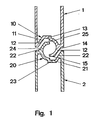
- the side wall consists of at least two planks 1, 2 which, after positive contact, are connected with the aid of a fixing member 31 inserted into the cylindrical cavity 30.
- the longitudinal edges of the planks 1, 2, which are in contact with an adjacent plank, are designed as partially open channels 10, 20.
- part 11 of the channel 10 of the one plank 1 overlaps part of the channel 20 of the other plank 2 and vice versa
- the other part 12 of the channel 10 of the one plank 1 is covered by a corresponding part 21 of the Channel 20 overlapped.
- the design of the inner surfaces 12, 22 of the overlapping parts 11, 21 corresponds to the outer surfaces 14, 24 of the overlapping parts 12, 22, the inner surfaces 12, 22 and the outer surfaces 14, 24 at least partially as flat surfaces, which serve as guide surfaces during assembly serve the planks 1,2, are formed.
- the inner and outer surfaces 12, 22, 14, 24 are advantageous to design as a whole flat and, furthermore, to arrange them at least partially obliquely to the plane of the planks 1, 2. Due to the at least partially oblique arrangement of the inner and outer surfaces 12, 22, 14, 24 - an angle of 15 ° to 35 ° which deviates from the plane of the planks 1, 2 has proven to be particularly advantageous - these may become apparent during assembly not a perfect match standing planks 1,2 when pushed together into the position necessary for the final connection, making an assembly gauge unnecessary.
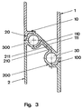
- one channel 10 or 20 can either be without a web, with a very short web 110,210, as shown in FIG. 4, or with a very pronounced web 110,210, as shown in FIG. 3, with the other channel 100 or 200 connected.
- the axis plane of the cylindrical cavities 30, 300 which arise when planks 1, 2 provided with two grooves 10, 100 or 20, 200 are joined together, is usually transverse to the plane of the planks 1, 2.
- the web 110, 210 is not too short in length, because it in turn serves as a support element in the above-mentioned sense and contributes to the increased loading of the side wall.
- the two channels 10, 100 or 20, 200 are advantageously arranged offset and connected by an inclined web 110, 210, as shown in FIG. 3.
- planks 1, 2 In addition to the bonding of the contact surfaces of the planks 1, 2, at least partial welding of the visible joints of the abutting planks 1, 2 is provided to further reinforce the side wall.
- the planks 1, 2 are advantageously chamfered at least at the points provided for the welding.
Landscapes
- Engineering & Computer Science (AREA)
- General Engineering & Computer Science (AREA)
- Mechanical Engineering (AREA)
- Polishing Bodies And Polishing Tools (AREA)
- Diaphragms For Electromechanical Transducers (AREA)
- Magnetic Heads (AREA)
- Finishing Walls (AREA)
- Roof Covering Using Slabs Or Stiff Sheets (AREA)
- Ladders (AREA)
- Rod-Shaped Construction Members (AREA)
- Auxiliary Methods And Devices For Loading And Unloading (AREA)
Priority Applications (1)
| Application Number | Priority Date | Filing Date | Title |
|---|---|---|---|
| AT89810024T ATE69589T1 (de) | 1988-01-14 | 1989-01-11 | Bordwand. |
Applications Claiming Priority (2)
| Application Number | Priority Date | Filing Date | Title |
|---|---|---|---|
| CH135/88 | 1988-01-14 | ||
| CH13588 | 1988-01-14 |
Publications (2)
| Publication Number | Publication Date |
|---|---|
| EP0324722A1 true EP0324722A1 (fr) | 1989-07-19 |
| EP0324722B1 EP0324722B1 (fr) | 1991-11-21 |
Family
ID=4180047
Family Applications (1)
| Application Number | Title | Priority Date | Filing Date |
|---|---|---|---|
| EP89810024A Expired - Lifetime EP0324722B1 (fr) | 1988-01-14 | 1989-01-11 | Paroi latérale |
Country Status (4)
| Country | Link |
|---|---|
| EP (1) | EP0324722B1 (fr) |
| AT (1) | ATE69589T1 (fr) |
| DE (1) | DE58900456D1 (fr) |
| ES (1) | ES2027829T3 (fr) |
Cited By (3)
| Publication number | Priority date | Publication date | Assignee | Title |
|---|---|---|---|---|
| EP0845604A3 (fr) * | 1996-11-27 | 1998-08-05 | Deutsche Waggonbau AG | Raccordement de pièces pour structures planes, notamment pour segments de véhicules. |
| EP1609705A2 (fr) | 2004-06-23 | 2005-12-28 | Pongratz Trailer-Group GmbH | Ridelle pour remorque et procédé pour la production ou l'assemblage d'une telle ridelle |
| US20210276070A1 (en) * | 2020-03-06 | 2021-09-09 | emoono CO., LTD. | Aluminum assembly |
Citations (5)
| Publication number | Priority date | Publication date | Assignee | Title |
|---|---|---|---|---|
| DE1112098B (de) * | 1955-12-01 | 1961-08-03 | Linke Hofmann Busch | Ausbildung der Trennstellen von Spanten bei einem selbsttragenden Wagenkasten fuer Fahrzeuge, insbesondere Schienenfahrzeuge |
| FR1369730A (fr) * | 1962-10-31 | 1964-08-14 | Lavorazione Leghe Leggere S P | Structure à éléments assemblés pour parois latérales de la caisse de camions ou poids lourds |
| DE1559512A1 (de) * | 1965-12-01 | 1969-09-11 | Eschweiler Plastik Gmbh | Platte aus Kunststoff-Bauteilen,insbesondere Tuer- bzw. Torblatt |
| CH512697A (de) * | 1970-09-23 | 1971-09-15 | Alusuisse | Aus Metallplanken gebildete ebene Fläche |
| FR2125088A5 (fr) * | 1971-02-05 | 1972-09-22 | Alusuisse |
-
1989
- 1989-01-11 DE DE8989810024T patent/DE58900456D1/de not_active Expired - Lifetime
- 1989-01-11 EP EP89810024A patent/EP0324722B1/fr not_active Expired - Lifetime
- 1989-01-11 AT AT89810024T patent/ATE69589T1/de active
- 1989-01-11 ES ES198989810024T patent/ES2027829T3/es not_active Expired - Lifetime
Patent Citations (5)
| Publication number | Priority date | Publication date | Assignee | Title |
|---|---|---|---|---|
| DE1112098B (de) * | 1955-12-01 | 1961-08-03 | Linke Hofmann Busch | Ausbildung der Trennstellen von Spanten bei einem selbsttragenden Wagenkasten fuer Fahrzeuge, insbesondere Schienenfahrzeuge |
| FR1369730A (fr) * | 1962-10-31 | 1964-08-14 | Lavorazione Leghe Leggere S P | Structure à éléments assemblés pour parois latérales de la caisse de camions ou poids lourds |
| DE1559512A1 (de) * | 1965-12-01 | 1969-09-11 | Eschweiler Plastik Gmbh | Platte aus Kunststoff-Bauteilen,insbesondere Tuer- bzw. Torblatt |
| CH512697A (de) * | 1970-09-23 | 1971-09-15 | Alusuisse | Aus Metallplanken gebildete ebene Fläche |
| FR2125088A5 (fr) * | 1971-02-05 | 1972-09-22 | Alusuisse |
Cited By (4)
| Publication number | Priority date | Publication date | Assignee | Title |
|---|---|---|---|---|
| EP0845604A3 (fr) * | 1996-11-27 | 1998-08-05 | Deutsche Waggonbau AG | Raccordement de pièces pour structures planes, notamment pour segments de véhicules. |
| EP1609705A2 (fr) | 2004-06-23 | 2005-12-28 | Pongratz Trailer-Group GmbH | Ridelle pour remorque et procédé pour la production ou l'assemblage d'une telle ridelle |
| US20210276070A1 (en) * | 2020-03-06 | 2021-09-09 | emoono CO., LTD. | Aluminum assembly |
| US11802580B2 (en) * | 2020-03-06 | 2023-10-31 | emoono CO., LTD. | Aluminum assembly |
Also Published As
| Publication number | Publication date |
|---|---|
| EP0324722B1 (fr) | 1991-11-21 |
| ATE69589T1 (de) | 1991-12-15 |
| ES2027829T3 (es) | 1992-06-16 |
| DE58900456D1 (de) | 1992-01-02 |
Similar Documents
| Publication | Publication Date | Title |
|---|---|---|
| DE203904T1 (de) | Schalungs- und bewehrungswand. | |
| DE2651281C2 (de) | Wandung aus vorgefertigten Platten, insbesondere für Kühlwagen oder Hochbauten | |
| EP0281983A2 (fr) | Système d'assemblage pour un bâti d'enceinte | |
| CH654805A5 (de) | Flachpalette und deren verwendung. | |
| EP0324722B1 (fr) | Paroi latérale | |
| DE2646020A1 (de) | Bauteilsatz zur herstellung von kastenmauern | |
| EP1163143B1 (fr) | Profile extrude sous forme de plaque | |
| DE2609388C3 (de) | Stabilisienings- und Ausrichtelement fur Gehrungsstoße zwischen zwei Bauprofilen | |
| DE102008037040A1 (de) | Distanzplatte | |
| DE19522285B4 (de) | Vertikalverbindung zwischen zwei Bauelementen | |
| DE3012855C2 (de) | Stabrost mit rechteckigen, aus Kunststoff bestehenden Rostelementen | |
| EP0039467A2 (fr) | Pièce d'écartement | |
| DE2841794A1 (de) | Betonbauelement in form einer platte | |
| DE4137641A1 (de) | Systembaukasten | |
| DE8017543U1 (de) | Zusammenschiebbare walze eines rolladens | |
| DE60212300T2 (de) | Träger für Schalungselemente | |
| WO1999007958A1 (fr) | Espaceur | |
| EP0584659B1 (fr) | Ensemble d'éléments pour la fabrication d'une paroi en briques de verre | |
| DE2754613C2 (de) | Rinnenschußverbindung | |
| DE3632154A1 (de) | Leichtmetall-strangprofil, insbesondere fuer die herstellung von eck- und stossverbindungen | |
| DE2305714C3 (de) | Holzgitterträger | |
| DE605539C (de) | Gewoelbte raumabschliessende Netzwerke aus von Knotenpunkt zu Knotenpunkt reichendenStaeben | |
| DE2914443A1 (de) | Traggeruest fuer ein zelt o.dgl. | |
| EP0129176A2 (fr) | Fixation d'angle résistante à la flexion | |
| EP0109968B1 (fr) | Rayonnage en bois |
Legal Events
| Date | Code | Title | Description |
|---|---|---|---|
| PUAI | Public reference made under article 153(3) epc to a published international application that has entered the european phase |
Free format text: ORIGINAL CODE: 0009012 |
|
| AK | Designated contracting states |
Kind code of ref document: A1 Designated state(s): AT BE CH DE ES FR GB IT LI NL SE |
|
| 17P | Request for examination filed |
Effective date: 19891127 |
|
| RAP1 | Party data changed (applicant data changed or rights of an application transferred) |
Owner name: ALUSUISSE-LONZA SERVICES AG |
|
| 17Q | First examination report despatched |
Effective date: 19910415 |
|
| ITF | It: translation for a ep patent filed | ||
| GRAA | (expected) grant |
Free format text: ORIGINAL CODE: 0009210 |
|
| AK | Designated contracting states |
Kind code of ref document: B1 Designated state(s): AT BE CH DE ES FR GB IT LI NL SE |
|
| REF | Corresponds to: |
Ref document number: 69589 Country of ref document: AT Date of ref document: 19911215 Kind code of ref document: T |
|
| REF | Corresponds to: |
Ref document number: 58900456 Country of ref document: DE Date of ref document: 19920102 |
|
| ET | Fr: translation filed | ||
| GBT | Gb: translation of ep patent filed (gb section 77(6)(a)/1977) | ||
| REG | Reference to a national code |
Ref country code: ES Ref legal event code: FG2A Ref document number: 2027829 Country of ref document: ES Kind code of ref document: T3 |
|
| PLBE | No opposition filed within time limit |
Free format text: ORIGINAL CODE: 0009261 |
|
| STAA | Information on the status of an ep patent application or granted ep patent |
Free format text: STATUS: NO OPPOSITION FILED WITHIN TIME LIMIT |
|
| 26N | No opposition filed | ||
| EAL | Se: european patent in force in sweden |
Ref document number: 89810024.3 |
|
| PGFP | Annual fee paid to national office [announced via postgrant information from national office to epo] |
Ref country code: GB Payment date: 19981223 Year of fee payment: 11 |
|
| PGFP | Annual fee paid to national office [announced via postgrant information from national office to epo] |
Ref country code: ES Payment date: 19990118 Year of fee payment: 11 |
|
| PGFP | Annual fee paid to national office [announced via postgrant information from national office to epo] |
Ref country code: SE Payment date: 19990125 Year of fee payment: 11 |
|
| PG25 | Lapsed in a contracting state [announced via postgrant information from national office to epo] |
Ref country code: GB Free format text: LAPSE BECAUSE OF NON-PAYMENT OF DUE FEES Effective date: 20000111 |
|
| PG25 | Lapsed in a contracting state [announced via postgrant information from national office to epo] |
Ref country code: SE Free format text: LAPSE BECAUSE OF NON-PAYMENT OF DUE FEES Effective date: 20000112 Ref country code: ES Free format text: LAPSE BECAUSE OF NON-PAYMENT OF DUE FEES Effective date: 20000112 |
|
| PGFP | Annual fee paid to national office [announced via postgrant information from national office to epo] |
Ref country code: FR Payment date: 20000118 Year of fee payment: 12 |
|
| PGFP | Annual fee paid to national office [announced via postgrant information from national office to epo] |
Ref country code: BE Payment date: 20000120 Year of fee payment: 12 Ref country code: AT Payment date: 20000120 Year of fee payment: 12 |
|
| GBPC | Gb: european patent ceased through non-payment of renewal fee |
Effective date: 20000111 |
|
| EUG | Se: european patent has lapsed |
Ref document number: 89810024.3 |
|
| PG25 | Lapsed in a contracting state [announced via postgrant information from national office to epo] |
Ref country code: AT Free format text: LAPSE BECAUSE OF NON-PAYMENT OF DUE FEES Effective date: 20010111 |
|
| PGFP | Annual fee paid to national office [announced via postgrant information from national office to epo] |
Ref country code: NL Payment date: 20010123 Year of fee payment: 13 |
|
| PG25 | Lapsed in a contracting state [announced via postgrant information from national office to epo] |
Ref country code: BE Free format text: LAPSE BECAUSE OF NON-PAYMENT OF DUE FEES Effective date: 20010131 |
|
| PGFP | Annual fee paid to national office [announced via postgrant information from national office to epo] |
Ref country code: CH Payment date: 20010206 Year of fee payment: 13 |
|
| PGFP | Annual fee paid to national office [announced via postgrant information from national office to epo] |
Ref country code: DE Payment date: 20010212 Year of fee payment: 13 |
|
| BERE | Be: lapsed |
Owner name: ALUSUISSE-LONZA SERVICES A.G. Effective date: 20010131 |
|
| PG25 | Lapsed in a contracting state [announced via postgrant information from national office to epo] |
Ref country code: FR Free format text: LAPSE BECAUSE OF NON-PAYMENT OF DUE FEES Effective date: 20010928 |
|
| REG | Reference to a national code |
Ref country code: FR Ref legal event code: ST |
|
| REG | Reference to a national code |
Ref country code: ES Ref legal event code: FD2A Effective date: 20010910 |
|
| PG25 | Lapsed in a contracting state [announced via postgrant information from national office to epo] |
Ref country code: LI Free format text: LAPSE BECAUSE OF NON-PAYMENT OF DUE FEES Effective date: 20020131 Ref country code: CH Free format text: LAPSE BECAUSE OF NON-PAYMENT OF DUE FEES Effective date: 20020131 |
|
| PG25 | Lapsed in a contracting state [announced via postgrant information from national office to epo] |
Ref country code: NL Free format text: LAPSE BECAUSE OF NON-PAYMENT OF DUE FEES Effective date: 20020801 Ref country code: DE Free format text: LAPSE BECAUSE OF NON-PAYMENT OF DUE FEES Effective date: 20020801 |
|
| REG | Reference to a national code |
Ref country code: CH Ref legal event code: PL |
|
| NLV4 | Nl: lapsed or anulled due to non-payment of the annual fee |
Effective date: 20020801 |
|
| PG25 | Lapsed in a contracting state [announced via postgrant information from national office to epo] |
Ref country code: IT Free format text: LAPSE BECAUSE OF NON-PAYMENT OF DUE FEES;WARNING: LAPSES OF ITALIAN PATENTS WITH EFFECTIVE DATE BEFORE 2007 MAY HAVE OCCURRED AT ANY TIME BEFORE 2007. THE CORRECT EFFECTIVE DATE MAY BE DIFFERENT FROM THE ONE RECORDED. Effective date: 20050111 |