EP0325128B1 - Dispositif pour ajuster et fixer des huisseries de portes et de fenêtres ou similaires dans des orifices muraux - Google Patents
Dispositif pour ajuster et fixer des huisseries de portes et de fenêtres ou similaires dans des orifices muraux Download PDFInfo
- Publication number
- EP0325128B1 EP0325128B1 EP89100241A EP89100241A EP0325128B1 EP 0325128 B1 EP0325128 B1 EP 0325128B1 EP 89100241 A EP89100241 A EP 89100241A EP 89100241 A EP89100241 A EP 89100241A EP 0325128 B1 EP0325128 B1 EP 0325128B1
- Authority
- EP
- European Patent Office
- Prior art keywords
- frame
- wall
- spindle
- retainer
- adjusting
- Prior art date
- Legal status (The legal status is an assumption and is not a legal conclusion. Google has not performed a legal analysis and makes no representation as to the accuracy of the status listed.)
- Expired - Lifetime
Links
- 230000000284 resting effect Effects 0.000 claims abstract 2
- 238000000034 method Methods 0.000 description 4
- 210000000078 claw Anatomy 0.000 description 2
- 238000005553 drilling Methods 0.000 description 2
- 230000005923 long-lasting effect Effects 0.000 description 2
- 230000001154 acute effect Effects 0.000 description 1
- 238000010276 construction Methods 0.000 description 1
- 238000006073 displacement reaction Methods 0.000 description 1
- 239000006223 plastic coating Substances 0.000 description 1
- 238000006748 scratching Methods 0.000 description 1
- 230000002393 scratching effect Effects 0.000 description 1
Images

Classifications
-
- E—FIXED CONSTRUCTIONS
- E04—BUILDING
- E04F—FINISHING WORK ON BUILDINGS, e.g. STAIRS, FLOORS
- E04F21/00—Implements for finishing work on buildings
- E04F21/0007—Implements for finishing work on buildings for mounting doors, windows or frames; their fitting
- E04F21/0015—Implements for finishing work on buildings for mounting doors, windows or frames; their fitting for mounting frames
Definitions
- the invention relates to a device for adjusting and tightening window and door frames or the like in wall openings according to the preamble of claim 1.
- Wall openings into which window or door frames are inserted generally have a clear width that more or less exceeds the external dimensions of the frame.
- the prefabricated frame must therefore be adjusted with respect to three orthogonal axes in the wall opening before it is finally fixed in it. It is known to use frames and / or the frame Clamp the wedges in the wall opening after adjustment. This process is cumbersome and time consuming. Removing the wedges and washers is also relatively cumbersome after the frame is finally attached.
- a device of the type mentioned at the outset which is used exclusively for the adjustment of a frame in the vertical direction.
- vertical posts of the frame are overlapped laterally by claws, which is part of a holder with a guide section for a spindle or a guide rod.
- Each claw has a locking screw for clamping the post.
- To move and adjust the frame transversely to the threaded spindle it must be moved including its lateral devices, its support elements sliding over the rough floor or the ceiling of the opening. This makes the adjustment of the frame across the threaded spindle difficult and undesirable inaccuracies are promoted.
- the invention has for its object to provide a device for adjusting and tightening window and door frames or the like in wall openings, which facilitates precise alignment and tightening of window and door frames in any frame positions.
- a threaded spindle is provided which is supported directly on the opening wall via a support element.
- the support element is preferably rotatably mounted on the free end of the threaded spindle.
- the holder sits with a spindle nut section on the spindle. By rotating the threaded spindle, the entire holder is therefore axially adjusted relative to the spindle.
- the bracket overlaps the frame section with support sections laterally in such a way that the frame is fixed in the direction of the associated opening wall, but can be displaced transversely thereto.
- a frame can be raised or lowered by rotating the threaded spindle in accordance with the desired end position.
- the frame can also be used in the Bracket to be moved laterally. The position of the frame with respect to an axis lying in the plane of the wall opening is therefore adjusted with the aid of the threaded spindle, while the position is adjusted transversely to this by moving the frame in the holder.
- the device according to the invention also has the advantage that it is used regardless of how the frame for the masonry opening is to be installed along an axis perpendicular to it.
- the use of the device according to the invention is also independent of all types of wall and stop.
- the device according to the invention makes use of the fact that the frames normally have sufficient inherent stability, that deformation does not occur during the adjustment process or afterwards.
- the invention provides that the bracket is a fixed, preferably facing the opening wall Has support, while the other support is formed by a resilient portion of the bracket.
- the resilient section allows a more or less firm grasping of the frame section from opposite sides, but at the same time a problem-free removal of the holder.
- the resilient section is preferably formed by a leaf spring which is connected to the holder and which has a bent section which can be brought into engagement with the facing frame surface.
- the leaf spring can therefore be provided with a projection which engages behind a raised edge of the frame.
- the resilient section is preferably adjustable.
- the adjustment can take place, for example, in that the resilient section is fixed to the holder by means of a screw which is attached in an elongated hole in the holder.
- the holder is preferably provided with a flat plate in which one or two elongated holes can be formed. The plate can also be brought into engagement with the front of the frame section in order to also fix the frame in the direction of an axis perpendicular to the plane of the opening.
- an embodiment of the invention provides that the surfaces which come into contact with the frame section have a relative soft layer are coated, for example a suitable plastic coating.
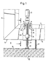
- masonry is indicated at 10. It contains an opening 11, of which an opening wall 12 is shown.
- a horizontal frame section is of a window or door frame 14, which is only indicated 15, which is connected via a corner to a vertical frame section 16.
- the profile of the frame can be seen in FIG. It can also be seen that it has a circumferential raised edge 17 on the inside at one end.
- An adjusting and tensioning device 20 can also be seen in FIGS. 1 and 2. It has a threaded spindle 21 which is supported on the opening wall 12 via a plate 22 which is rotatably connected to the end of the threaded spindle 21. At the other end, the threaded spindle has a handle 23.
- the threaded spindle 21 extends through a nut section 24 which is attached to the outside of a plate 25 which is provided with angled sections 26, 27 at the upper and lower ends.
- the angled sections 26, 27 point away from the nut section 24.
- the lower angled section 26 forms a fixed support.
- the sections 26, 27 are at a distance from one another which is greater than the maximum width or height of the profile strips for window or door frames.
- the plate 25 is provided in one end region with two elongated holes 28, 29 through which locking screws 30, 31 are guided for fastening a leaf spring 32 on the inside of the plate 25.
- a leaf spring 32 On the fixed portion of the leaf spring 32 extends a horizontal portion 33 which is bent back at an acute angle and forms a resilient leg 34 which is bent at right angles at the end with a portion 35. Die Sections 34, 35 form a downward projection, which resiliently rests against the inner surface of the frame 14, the strip or raised edge 17 being engaged behind.
- the relaxed state of the leaf spring 32 is indicated by the dash-dotted line 36.
- the dashed line 37 indicates that the adjusting screws 30 have brought the leaf spring 32 into a different position for engagement with a frame section of different dimensions, as indicated by dashed lines at 39.
- the bracket formed from the supports 26 and 32 and the plate 25 can be adapted to the dimensions of the frame sections.
- the bracket can easily be snapped onto the frame and detached from it again.
- the threaded spindle 20 is screwed back somewhat, as can be seen in dashed lines at 40.
- the device 20 is used to set the exact height of the frame 14 by lifting or lowering the frame 14, preferably at least two devices 20 of the same type being attached to the frame 14.
- the frame is laterally aligned by moving it in the holder until the exact position is reached.
- holes are drilled into the masonry 10 with the aid of a drill, as can be seen, for example, at 41.
- the holes in the frame profile serve as a drilling template.
- a long-lasting screw 42 is screwed into the wall hole 41 through the hole in the frame profile, the thread of the screw 42 also forming into the hole in the frame profile so that the frame 14 in the position adjusted by the device 20 is finally adjusted with the aid of such screws 42 can be fixed.
- the holder can be detached from the frame section by simply tilting the device 20.
Landscapes
- Engineering & Computer Science (AREA)
- Architecture (AREA)
- Civil Engineering (AREA)
- Structural Engineering (AREA)
- Door And Window Frames Mounted To Openings (AREA)
- Hinges (AREA)
- Patch Boards (AREA)
- Securing Of Glass Panes Or The Like (AREA)
Claims (9)
- Dispositif pour ajuster et fixer par serrage des huisseries de portes et de fenêtres ou similaires, dans des orifices de murs, comportant au moins une broche filetée (21) que l'on peut faire tourner à la main, qui s'appuie directement, par l'intermédiaire d'un organe d'appui (22) se trouvant à son extrémité libre, sur la paroi de l'orifice, et sur laquelle est disposée une fixation (25, 26, 32), reliable à une partie de cadre, fixation qui présente un élément faisant écrou de broche (24) et qui à l'aide de parties d'appui (26, 32) reprend, de façon amovible, la partie de cadre (15) par des côtés situés à une certaine distance l'un de l'autre,
caractérisé en ce que les parties d'appui (26, 32) ont une direction perpendiculaire à la broche filetée (21), en ce que la fixation présente un appui fixe (26) et en ce que l'autre appui est formé par une partie faisant ressort (32) de la fixation. - Dispositif suivant la revendication 1, caractérisé en ce que l'appui fixe (26) est tourné vers la paroi (12) de l'orifice.
- Dispositif suivant la revendication 1 ou la revendication 2, caractérisé en ce qu'un ressort à lame (32) peut être relié à la fixation, et, peut être mis en prise par une partie repliée (34, 35), contre la surface de cadre tournée vers lui.
- Dispositif suivant la revendication 3, caractérisé en ce que le ressort à lame (32) présente une saillie qui prend par derrière une arête saillante (17) du cadre (14).
- Dispositif suivant l'une quelconque des revendications 1 à 4, caractérisé en ce qu'un appui (32) est disposé de façon réglable.
- Dispositif suivant l'une quelconque des revendications 1 à 5, caractérisé en ce que la partie formant ressort (32) est réglable.
- Dispositif suivant l'une quelconque des revendications 1 à 6, caractérisé en ce que les appuis (26, 32) sont portés par une plaque plane (25) contre laquelle vient s'appuyer la face extérieure, tournée vers elle, de la partie de cadre.
- Dispositif suivant la revendication 5 et la revendication 7, caractérisé en ce que la plaque (25) présente au moins un trou oblong (28, 29) pour recevoir une vis de blocage (30, 31) reliable avec la partie formant ressort (32).
- Dispositif suivant l'une quelconque des revendications 1 à 8, caractérisé en ce qu'au moins les surfaces venant au contact de la partie de cadre sont recouvertes par une couche relativement tendre.
Priority Applications (1)
| Application Number | Priority Date | Filing Date | Title |
|---|---|---|---|
| AT89100241T ATE80193T1 (de) | 1988-01-20 | 1989-01-07 | Vorrichtung zum justieren und festspannen von fenster- und tuerrahmen oder dergleichen in maueroeffnungen. |
Applications Claiming Priority (2)
| Application Number | Priority Date | Filing Date | Title |
|---|---|---|---|
| DE3801475 | 1988-01-20 | ||
| DE3801475A DE3801475A1 (de) | 1988-01-20 | 1988-01-20 | Vorrichtung zum justieren und festspannen von fenster- und tuerrahmen oder dergleichen in maueroeffnungen |
Publications (3)
| Publication Number | Publication Date |
|---|---|
| EP0325128A2 EP0325128A2 (fr) | 1989-07-26 |
| EP0325128A3 EP0325128A3 (en) | 1989-10-25 |
| EP0325128B1 true EP0325128B1 (fr) | 1992-09-02 |
Family
ID=6345592
Family Applications (1)
| Application Number | Title | Priority Date | Filing Date |
|---|---|---|---|
| EP89100241A Expired - Lifetime EP0325128B1 (fr) | 1988-01-20 | 1989-01-07 | Dispositif pour ajuster et fixer des huisseries de portes et de fenêtres ou similaires dans des orifices muraux |
Country Status (7)
| Country | Link |
|---|---|
| US (1) | US4947594A (fr) |
| EP (1) | EP0325128B1 (fr) |
| AT (1) | ATE80193T1 (fr) |
| AU (1) | AU605014B2 (fr) |
| DE (2) | DE3801475A1 (fr) |
| ES (1) | ES2034401T3 (fr) |
| IE (1) | IE890154L (fr) |
Families Citing this family (22)
| Publication number | Priority date | Publication date | Assignee | Title |
|---|---|---|---|---|
| DE9301556U1 (de) * | 1993-02-04 | 1993-03-25 | EJOT Verbindungstechnik GmbH & Co. KG, 5290 Berleburg | Justiervorrichtung für Blendrahmen |
| DE29511658U1 (de) * | 1995-07-19 | 1996-01-04 | Ristau, Wolfgang, 27313 Dörverden | Zargenstütze |
| DE19617101A1 (de) * | 1996-04-19 | 1997-10-23 | Bertold Dipl Ing Weinberg | Vorrichtung zum Justieren und Montieren von Rahmenbauteilen |
| US5890297A (en) * | 1996-11-12 | 1999-04-06 | Frasheski; Quentin | Door-set device |
| DE19737230C1 (de) * | 1997-08-27 | 1999-06-10 | Bessey & Sohn | Distanzstück und Feststellvorrichtung zum Ausrichten und Fixieren von Fensterrahmen oder Türfuttern |
| USD411120S (en) | 1998-05-06 | 1999-06-22 | William Parry | Door hanging kit |
| WO2000000709A1 (fr) * | 1998-06-26 | 2000-01-06 | Wizard Tools And Construction Materials Llc | Equerre-gabarit a reserve en decoupe et forme enveloppante pour le montage de fenetres |
| DE29900339U1 (de) * | 1999-01-12 | 2000-09-21 | EJOT Verbindungstechnik GmbH & Co. KG, 57334 Bad Laasphe | Justiervorrichtung mit Spannelement |
| US6216402B1 (en) * | 1999-08-19 | 2001-04-17 | Van De Laar Kevin | Window installation system |
| FR2805840B1 (fr) | 2000-03-01 | 2002-05-03 | Paul Serge Salette | Dispositif et procede de pose d'un encadrement de porte ou de fenetre dans une ouverture de mur, en vue du positionnement de l'encadrement et de son maintien durant sa fixation |
| US6532703B1 (en) * | 2001-04-12 | 2003-03-18 | Alan K. Barrens | Portable screen door |
| DE20119699U1 (de) | 2001-12-05 | 2002-02-14 | Baumann, Dirk, 69469 Weinheim | Vorrichtung für die Montage eines Geländers |
| DE10200713B4 (de) * | 2002-01-10 | 2012-04-19 | Werner Rausch | Haken zum Anpressen von Teilen an eine Bauwerksoberfläche |
| US20040231808A1 (en) * | 2003-05-19 | 2004-11-25 | Belanger Michael B. | Folding grille assembly |
| US20050210689A1 (en) * | 2004-03-27 | 2005-09-29 | Carroll William P | Reversible doorjamb square |
| US7331146B1 (en) * | 2004-06-29 | 2008-02-19 | B3 Products, Inc. | Window and door jamb adjustment system |
| US20070175122A1 (en) * | 2006-01-04 | 2007-08-02 | Bennett Bruce J | Device for vertically adjusting the jamb of a hollow door frame |
| DE102006053555B4 (de) * | 2006-11-14 | 2009-06-18 | Rico Bohn | Montagehilfswerkzeug für eine Türzarge |
| US8251356B2 (en) * | 2008-05-09 | 2012-08-28 | Eschenburg Jerry E | Door installation |
| DE102009010832B4 (de) * | 2009-02-28 | 2017-11-30 | Bruno Niewiara | Montagevorrichtung und Montageverfahren für Tür- und/oder Fensterzargen |
| CN105649479B (zh) * | 2015-12-31 | 2018-06-19 | 苏州锟鹏肖氏建材有限公司 | 一种建筑门窗的安装方法 |
| CA3230065A1 (fr) * | 2021-09-02 | 2023-03-09 | Stauf Design aus Holz GmbH | Dispositif de positionnement de cadre et procede de positionnement d'un cadre |
Family Cites Families (14)
| Publication number | Priority date | Publication date | Assignee | Title |
|---|---|---|---|---|
| US1778496A (en) * | 1929-09-19 | 1930-10-14 | John H Hobbs | Door and frame gauge |
| US2748493A (en) * | 1952-08-12 | 1956-06-05 | George R Williams | Jig mechanism for installing doors and door frames |
| US2945568A (en) * | 1954-01-20 | 1960-07-19 | Chasteney Ruth Goodhue | Partition structure |
| FR1132243A (fr) * | 1955-09-22 | 1957-03-06 | Procédé de pose d'huisseries et appareillage faisant application de ce procédé | |
| US2881813A (en) * | 1957-03-19 | 1959-04-14 | Lacoste Francois | Door and window frame supporting structure |
| US2949948A (en) * | 1957-08-06 | 1960-08-23 | Warren B Zern | System for hanging doors |
| FR1227626A (fr) * | 1959-06-15 | 1960-08-22 | Appareillage pour la mise en place des châssis de fenêtres ou de portes avant scellement | |
| FR1241207A (fr) * | 1959-08-03 | 1960-09-16 | Dispositif destiné à faciliter la pose des huisseries | |
| US3830024A (en) * | 1972-09-14 | 1974-08-20 | Warn Key Inc | Stabilizing and anchoring device for mobile homes and similar structures |
| US4141192A (en) * | 1978-03-27 | 1979-02-27 | Pius Augustine | Door brace for facilitating hanging |
| GB2134433B (en) * | 1983-01-13 | 1986-05-14 | Kenneth Charles Stewart | Door hanging device |
| DE8312658U1 (de) * | 1983-04-29 | 1983-10-27 | Schulte, Andreas, 4440 Rheine | Montagevorrichtung fuer fenster und tueren |
| US4685216A (en) * | 1986-07-02 | 1987-08-11 | Robert E. Garland | Arch door marking gauge |
| DE8712869U1 (de) * | 1987-09-24 | 1987-10-29 | Biermaier, Johann, 8221 Hufschlag | Schwellenlehre |
-
1988
- 1988-01-20 DE DE3801475A patent/DE3801475A1/de not_active Withdrawn
-
1989
- 1989-01-07 DE DE8989100241T patent/DE58902164D1/de not_active Expired - Fee Related
- 1989-01-07 EP EP89100241A patent/EP0325128B1/fr not_active Expired - Lifetime
- 1989-01-07 ES ES198989100241T patent/ES2034401T3/es not_active Expired - Lifetime
- 1989-01-07 AT AT89100241T patent/ATE80193T1/de active
- 1989-01-19 IE IE890154A patent/IE890154L/xx unknown
- 1989-01-19 AU AU28629/89A patent/AU605014B2/en not_active Expired - Fee Related
- 1989-01-23 US US07/299,373 patent/US4947594A/en not_active Expired - Fee Related
Also Published As
| Publication number | Publication date |
|---|---|
| DE3801475A1 (de) | 1989-08-03 |
| US4947594A (en) | 1990-08-14 |
| ATE80193T1 (de) | 1992-09-15 |
| EP0325128A3 (en) | 1989-10-25 |
| DE58902164D1 (de) | 1992-10-08 |
| AU2862989A (en) | 1989-07-20 |
| AU605014B2 (en) | 1991-01-03 |
| EP0325128A2 (fr) | 1989-07-26 |
| IE890154L (en) | 1989-07-20 |
| ES2034401T3 (es) | 1993-04-01 |
Similar Documents
| Publication | Publication Date | Title |
|---|---|---|
| EP0325128A2 (fr) | Dispositif pour ajuster et fixer des huisseries de portes et de fenêtres ou similaires dans des orifices muraux | |
| DE2714082C2 (de) | Scharnier | |
| EP0841032A2 (fr) | Dispositif pour la fixation réglable des panneaux, en particulier panneaux de verre ou similaires | |
| EP0518177A1 (fr) | Gabarit de perçage à former un certain modèle de trous forés sur des pièces | |
| DE4108455C2 (de) | Montagezwinge zum Montieren eines Türfutters einer Türzarge | |
| EP4130495B1 (fr) | Système de fixation destiné à la fixation d'une pièce rapportée et procédé de fixation et d'ajustement de la pièce rapportée | |
| EP0602456A1 (fr) | Collier pour tuyaux | |
| EP1132560B1 (fr) | Charnière et procédé de réglage en hauteur d'une charnière | |
| DE2611323B2 (de) | Einstellvorrichtung für eine der Höhe nach einstellbare obere Schiene eines Schiebeflügels | |
| DE20119997U1 (de) | Befestigungsvorrichtung | |
| DE2553263C2 (de) | Befestigungselement zur Halterung von C-förmigen Profilen an Rahmen, Tragschienen o.dgl. | |
| DE19646575A1 (de) | Vorrichtung zur justierbaren Halterung von Platten, insbesondere von Glasscheiben oder dergleichen | |
| EP0445363A1 (fr) | Dispositif de fraisage ou perçage | |
| DE10109098A1 (de) | Bandaufnahmevorrichtung zur Anbringung an einem Tür- oder Fensterflügel oder an einer Zarge | |
| DE102016206722B4 (de) | Klemmhalterung für eine Spannschnur einer Beschattungsanlage und Beschattungsanlage | |
| CH693350A5 (de) | Ausziehrahmen für Hochschränke. | |
| EP3636841A1 (fr) | Dispositif de montage pour un élément encastré | |
| DE29608455U1 (de) | Befestigungsvorrichtung, nämlich für Bretter, Regalbretter o.dgl. | |
| DE9301556U1 (de) | Justiervorrichtung für Blendrahmen | |
| AT411131B (de) | Ausziehrahmen für hochschränke mit vertikalen und horizontalen rahmenschenkeln aus profilschienen | |
| EP4471228A1 (fr) | Support de caisson et son procédé d'assemblage | |
| EP0718549B1 (fr) | Dispositif de fixation | |
| DE3427397A1 (de) | Band fuer tueren, fenster und dergleichen | |
| DE20103148U1 (de) | Justiervorrichtung für ein in einer Gebäudeöffnung einsetzbares Einbauteil, z.B. einen Fenster- oder Türrahmen | |
| AT409212B (de) | Vorhangstangenträger |
Legal Events
| Date | Code | Title | Description |
|---|---|---|---|
| PUAI | Public reference made under article 153(3) epc to a published international application that has entered the european phase |
Free format text: ORIGINAL CODE: 0009012 |
|
| AK | Designated contracting states |
Kind code of ref document: A2 Designated state(s): AT DE ES FR GB |
|
| PUAL | Search report despatched |
Free format text: ORIGINAL CODE: 0009013 |
|
| AK | Designated contracting states |
Kind code of ref document: A3 Designated state(s): AT DE ES FR GB |
|
| 17P | Request for examination filed |
Effective date: 19891123 |
|
| 17Q | First examination report despatched |
Effective date: 19910102 |
|
| GRAA | (expected) grant |
Free format text: ORIGINAL CODE: 0009210 |
|
| AK | Designated contracting states |
Kind code of ref document: B1 Designated state(s): AT DE ES FR GB |
|
| REF | Corresponds to: |
Ref document number: 80193 Country of ref document: AT Date of ref document: 19920915 Kind code of ref document: T |
|
| REF | Corresponds to: |
Ref document number: 58902164 Country of ref document: DE Date of ref document: 19921008 |
|
| GBT | Gb: translation of ep patent filed (gb section 77(6)(a)/1977) | ||
| ET | Fr: translation filed | ||
| PG25 | Lapsed in a contracting state [announced via postgrant information from national office to epo] |
Ref country code: GB Effective date: 19930107 |
|
| PG25 | Lapsed in a contracting state [announced via postgrant information from national office to epo] |
Ref country code: ES Free format text: LAPSE BECAUSE OF NON-PAYMENT OF DUE FEES Effective date: 19930108 |
|
| REG | Reference to a national code |
Ref country code: ES Ref legal event code: FG2A Ref document number: 2034401 Country of ref document: ES Kind code of ref document: T3 |
|
| PLBE | No opposition filed within time limit |
Free format text: ORIGINAL CODE: 0009261 |
|
| STAA | Information on the status of an ep patent application or granted ep patent |
Free format text: STATUS: NO OPPOSITION FILED WITHIN TIME LIMIT |
|
| 26N | No opposition filed | ||
| GBPC | Gb: european patent ceased through non-payment of renewal fee |
Effective date: 19930107 |
|
| PG25 | Lapsed in a contracting state [announced via postgrant information from national office to epo] |
Ref country code: FR Effective date: 19930930 |
|
| REG | Reference to a national code |
Ref country code: FR Ref legal event code: ST |
|
| PGFP | Annual fee paid to national office [announced via postgrant information from national office to epo] |
Ref country code: AT Payment date: 19951219 Year of fee payment: 8 |
|
| PGFP | Annual fee paid to national office [announced via postgrant information from national office to epo] |
Ref country code: DE Payment date: 19961218 Year of fee payment: 9 |
|
| PG25 | Lapsed in a contracting state [announced via postgrant information from national office to epo] |
Ref country code: AT Effective date: 19970107 |
|
| PG25 | Lapsed in a contracting state [announced via postgrant information from national office to epo] |
Ref country code: DE Free format text: LAPSE BECAUSE OF NON-PAYMENT OF DUE FEES Effective date: 19981001 |
|
| REG | Reference to a national code |
Ref country code: ES Ref legal event code: FD2A Effective date: 20020916 |