EP0325399A2 - Datenaufzeichnungsträger - Google Patents
Datenaufzeichnungsträger Download PDFInfo
- Publication number
- EP0325399A2 EP0325399A2 EP89300383A EP89300383A EP0325399A2 EP 0325399 A2 EP0325399 A2 EP 0325399A2 EP 89300383 A EP89300383 A EP 89300383A EP 89300383 A EP89300383 A EP 89300383A EP 0325399 A2 EP0325399 A2 EP 0325399A2
- Authority
- EP
- European Patent Office
- Prior art keywords
- upstand
- disc substrate
- magnetic clamping
- information recording
- upper flange
- Prior art date
- Legal status (The legal status is an assumption and is not a legal conclusion. Google has not performed a legal analysis and makes no representation as to the accuracy of the status listed.)
- Granted
Links
Images
Classifications
-
- G—PHYSICS
- G11—INFORMATION STORAGE
- G11B—INFORMATION STORAGE BASED ON RELATIVE MOVEMENT BETWEEN RECORD CARRIER AND TRANSDUCER
- G11B7/00—Recording or reproducing by optical means, e.g. recording using a thermal beam of optical radiation by modifying optical properties or the physical structure, reproducing using an optical beam at lower power by sensing optical properties; Record carriers therefor
- G11B7/24—Record carriers characterised by shape, structure or physical properties, or by the selection of the material
- G11B7/24018—Laminated discs
-
- G—PHYSICS
- G11—INFORMATION STORAGE
- G11B—INFORMATION STORAGE BASED ON RELATIVE MOVEMENT BETWEEN RECORD CARRIER AND TRANSDUCER
- G11B7/00—Recording or reproducing by optical means, e.g. recording using a thermal beam of optical radiation by modifying optical properties or the physical structure, reproducing using an optical beam at lower power by sensing optical properties; Record carriers therefor
- G11B7/24—Record carriers characterised by shape, structure or physical properties, or by the selection of the material
-
- G—PHYSICS
- G11—INFORMATION STORAGE
- G11B—INFORMATION STORAGE BASED ON RELATIVE MOVEMENT BETWEEN RECORD CARRIER AND TRANSDUCER
- G11B23/00—Record carriers not specific to the method of recording or reproducing; Accessories, e.g. containers, specially adapted for co-operation with the recording or reproducing apparatus ; Intermediate mediums; Apparatus or processes specially adapted for their manufacture
- G11B23/0014—Record carriers not specific to the method of recording or reproducing; Accessories, e.g. containers, specially adapted for co-operation with the recording or reproducing apparatus ; Intermediate mediums; Apparatus or processes specially adapted for their manufacture record carriers not specifically of filamentary or web form
- G11B23/0021—Record carriers not specific to the method of recording or reproducing; Accessories, e.g. containers, specially adapted for co-operation with the recording or reproducing apparatus ; Intermediate mediums; Apparatus or processes specially adapted for their manufacture record carriers not specifically of filamentary or web form discs
- G11B23/0028—Details
- G11B23/0035—Details means incorporated in the disc, e.g. hub, to enable its guiding, loading or driving
Definitions
- This invention relates to information recording media which are used as optical discs and the like, particularly information recording media which are set by a magnetic clamping system.
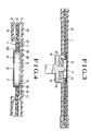
- FIG. 3 of the accompanying drawings is a cross-sectional view showing the state of a conventional information recording medium clamped by the magnetic clamping system
- Fig. 4 is a partially enlarged view thereof.
- reference numeral 1 designates an information recording medium, wherein a recording layer 3 is formed on one side of a disc substrate 2, the top surface of said recording layer is covered with a protective layer 4, and a magnetic clamping hub 6 of the dish-like shape is fitted into a center hole 5 of said disc substrate.
- the magnetic clamping hub 6 is formed by pressing a magnetic metal plate into a dish-like form, and the thus dished hub has a spindle hole 8 at the centre of said hub.
- a cylindrical upstand portion 9 of the hub 6 is inserted into the center hole 5 of the disc substrate 2, and the upper flange portion 10 of the hub 6 is fixed by means of an adhesive 11 to the inner peripheral surface of the protective layer 4 covering the recording layer 3 and the disc substrate 2.
- the above-mentioned information recording medium 1 is contained in a cartridge 12, and the cartridge 12 is placed on a disc drive 13.
- the disc drive 13 is so designed that the magnetic clamping hub 6 of the information recording medium 1 is inserted into a clamping area 15 formed in a turn table 14, the inserted hub 6 is clamped by means of a magnet 16, and a spindle 17 projecting at the center portion of the turn table 14 is inserted into the spindle hole 8 of the magnetic clamping hub 6, whereby the information recording medium 1 is positioned.
- the turn table 14 rotates in this state, the information recording medium 1 rotates, and the recording layer 3 is irradiated through windows (not shown) provided at the lower side of the cartridge 12 with laser beam or the like, thereby storing or reading information.
- This invention is intended to solve the above-mentioned problems, and it is an object of the invention to provide information recording media in which a disc substrate and a magnetic clamping hub can be attached satisfactorily to each other while maintaining a coaxial relationship between said disc substrate and said magnetic clamping hub.
- the information recording medium of the present invention by which the above-mentioned object of the invention is attained, comprises a disc substrate having at least laminated thereon a recording layer and having at the center thereof a center hole, and a magnetic clamping hub fitted into the center hole of this disc substrate, said magnetic clamping hub having a spindle hole at the center of the base thereof, a cylindrical first upstand portion rising from an outer periphery of the base, an upper flange portion of said first upstand portion extending from an outer periphery of a top end portion of this first upstand portion and being attached to an inner peripheral surface of the disc substrate, and a concave portion formed at a corner portion of the first upstand portion and upper flange portion.
- the information recording medium comprising a medium substrate having laminated thereon a recording layer and having at the center thereof a center hole, and a magnetic clamping hub fitted into the center hole of the disc substrate, said magnetic clamping hub having a spindle hole at the center of a base surface thereof, a cylindrical first upstand portion rising from an outer peripheral of the base in the direction almost at right angles to the base, an upper flange portion of the first upstand portion extending form an outer periphery of a top end of this upstand portion in the direction almost at right angles to the upstand portion and being bonded to an inner peripheral surface of the disc substrate or a protective layer coated on the disc substrates, and a concave portion formed at a corner portion of the first upstand portion and the upper flange portion.
- the magnetic clamping hub has a second upstand portion around the spindle hole into which a spindle of a disc drive is inserted.
- the information recording medium is intended to include all media which record information on a recording layer thereof, such as optical discs, flexible optical discs and the like.
- the magnetic clamping hub used in the present invention includes all the hubs formed from magnetic metals, plastics blended with magnetic materials, and the like magnetic materials.
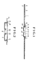
- this information recording medium of the present invention because a concave portion is formed at a corner portion of the upper flange and upstand portions of the magnetic clamping hub, no interference of the edge portion of the disc substrate with the corner portion occurs. On that account, even when the corner portion of the magnetic clamping hub irregularly varies, the disc substrate and the magnetic clamping hub can be maintained at a coaxial state by making a small gap between the disc substrate and the magnetic clamping hub and, at the same time, the adhesion between the information recording medium and the magnetic claimping hub is improved by filling the concave portion with an adhesive.
- the disc substrate can be maintained at a state perpendicular to the spindle of the disc drive, because surface deflection of the disc substrate is inhibited at the time when the disc substrate is mounted on the disc drive or the information recording medium rotates on the turn table.
- reference numeral 1 designates an information recording medium
- reference numeral 2 designates a disc substrate
- reference numeral 3 designates a recording layer
- reference numeral 4 designates a protective layer
- reference numeral 5 designates a center hole
- reference numerals 6 and 6a designate a magnetic clamping hub
- reference numeral 7 designates a base portion
- reference numeral 8 designates a spindle hole
- reference numeral 9 designates an first upstand portion
- reference numeral 10 designates an upper flange portion
- reference numeral 11 designates an adhesive
- reference numeral 12 designates a cartridge
- reference numeral 13 designates a disc drive
- reference numeral 18 designates a corner portion
- reference numeral 19 designates an edge portion
- reference numeral 21 designates a concave portion
- reference numeral 22 designates a second upstand portion.
- the information recording medium 1 of the present embodiment comprises a transparent plastic disc substrate 2 having on one side thereof a recording layer 3, the surface of said recording layer 3 being covered with a protective layer 4. There may be reflective layer (not shown) between the recording layer 3 and the protective layer 4.
- Such information recording medium 1 has at the center thereof a center hole 5 into which a magnetic clamping hub 6a is fitted.
- the magnetic clamping hub 6a is formed by pressing a circular magnetic metal plate into a dish-like shape, and has a cylindrical first upstand portion 9 and an upper flange portion 10, wherein a concave portion 21 is formed at the side of a corner portion 18 formed between the cylindrical first upstand portion 9 and the upper flange portion 10.
- a cylindrical second upstand portion rises from a base portion 7 of said hub 6a and is engaged with a spindle 17.
- the first upstand portion 9 is raised from an outer periphery of the base portion 7 in the direction almost at right angles to the base portion 7, and the upper flange portion 19 extends from an outer periphery of the upper end of the first upstand portion 9 in the direction almost at right angles to the upstand portion.
- the upper flange portion 10 is bonded with an adhesive 11 to the inner peripheral surface of the protective layer 4 coated on the disc substrate 2. When no protective layer is coated on the surface of the disc substrate 2, the upper flange portion 10 is bonded directly to the inner peripheral surface of the disc substrate 2.
- the upper flange portion 10 may be attached to the protective layer 4 or the disc substrate 2 without adhesive 11, for example by means of calking.
- the concave portion 21 is formed so that it caves preferably in above the bottom surface of the upper flange portion 10.
- the information recording medium 1 thus composed in the manner as mentioned above is used in the same way as in the convention ones.
- this information recording medium 1 because the concave portion 21 is formed at the corner portion 18 of the magnetic clamping hub 6a, irregularity in bending radius caused by the formation of the corner portion 18 is absorved by the concave portion 21 and no interference of the edge portion 19 of the disc substrate 2 with the corner portion 18 occurs.
- the disc substrate 2 can firmly attached to the upstand portion 9 even when a gap therebetween is made small.
- the center of the disc substrate 2 agrees with that of the magnetic clamping hub 6a, retaining a highly assured coaxial state between said disc substrate and said clamping hub.
- the concave portion 21 is filled with the adhesive 11, a high adhesive strength is attained.
- the magnetic clamping hub used in the invention may include injection-molded products of other molded products of plastics blended with magnetic materials.
Landscapes
- Optical Record Carriers And Manufacture Thereof (AREA)
- Holo Graphy (AREA)
- Magnetic Record Carriers (AREA)
- Holding Or Fastening Of Disk On Rotational Shaft (AREA)
Applications Claiming Priority (2)
| Application Number | Priority Date | Filing Date | Title |
|---|---|---|---|
| JP4883/88 | 1988-01-19 | ||
| JP1988004883U JP2537348Y2 (ja) | 1988-01-19 | 1988-01-19 | 光ディスク |
Publications (3)
| Publication Number | Publication Date |
|---|---|
| EP0325399A2 true EP0325399A2 (de) | 1989-07-26 |
| EP0325399A3 EP0325399A3 (en) | 1990-12-27 |
| EP0325399B1 EP0325399B1 (de) | 1994-08-17 |
Family
ID=11596078
Family Applications (1)
| Application Number | Title | Priority Date | Filing Date |
|---|---|---|---|
| EP89300383A Expired - Lifetime EP0325399B1 (de) | 1988-01-19 | 1989-01-17 | Datenaufzeichnungsträger |
Country Status (6)
| Country | Link |
|---|---|
| EP (1) | EP0325399B1 (de) |
| JP (1) | JP2537348Y2 (de) |
| KR (1) | KR910006653B1 (de) |
| CN (2) | CN2044759U (de) |
| AT (1) | ATE110183T1 (de) |
| DE (1) | DE68917483T2 (de) |
Cited By (4)
| Publication number | Priority date | Publication date | Assignee | Title |
|---|---|---|---|---|
| EP0592872A3 (de) * | 1992-10-13 | 1995-02-15 | Fuji Photo Film Co Ltd | Magnetplattenkassette. |
| EP0667616A3 (de) * | 1994-02-15 | 1996-04-24 | Mitsubishi Chem Corp | Plattenkassette. |
| EP0920012A4 (de) * | 1996-08-08 | 1999-08-11 | Fuji Photo Film Co Ltd | Magnetische plattenkassette |
| WO2004059632A3 (en) * | 2002-12-30 | 2004-10-07 | Koninkl Philips Electronics Nv | Magnetically clamped optical disc and apparatus |
Families Citing this family (2)
| Publication number | Priority date | Publication date | Assignee | Title |
|---|---|---|---|---|
| US4944982A (en) * | 1988-04-04 | 1990-07-31 | Fuji Photo Film Co., Ltd. | Information recording medium having magnetizable hub |
| DE19631319A1 (de) * | 1995-08-15 | 1997-02-20 | Minnesota Mining & Mfg | Platte zur optischen Datenspeicherung |
Family Cites Families (8)
| Publication number | Priority date | Publication date | Assignee | Title |
|---|---|---|---|---|
| JPS606938Y2 (ja) * | 1980-08-14 | 1985-03-07 | ソニー株式会社 | 記録再生用デイスクカセツト |
| US4562505A (en) * | 1982-12-20 | 1985-12-31 | Verbatim Corporation | Flexible magnetic memory disk with metallic hub and method of manufacturing same |
| JPS60186565U (ja) * | 1984-05-18 | 1985-12-10 | ソニー株式会社 | 磁気デイスク |
| JPH079257Y2 (ja) * | 1984-06-22 | 1995-03-06 | 富士写真フイルム株式会社 | 磁気ディスクカ−トリッジ |
| JPS6113376U (ja) * | 1984-06-22 | 1986-01-25 | 富士写真フイルム株式会社 | 磁気デイスクカ−トリツジ |
| JPS6124877U (ja) * | 1984-07-19 | 1986-02-14 | ティーディーケイ株式会社 | デイスクカ−トリツジ |
| JPS61210540A (ja) * | 1985-03-15 | 1986-09-18 | Hitachi Maxell Ltd | 光デイスク |
| JPS61186565U (de) * | 1985-05-14 | 1986-11-20 |
-
1988
- 1988-01-19 JP JP1988004883U patent/JP2537348Y2/ja not_active Expired - Lifetime
-
1989
- 1989-01-17 AT AT89300383T patent/ATE110183T1/de active
- 1989-01-17 DE DE68917483T patent/DE68917483T2/de not_active Expired - Fee Related
- 1989-01-17 EP EP89300383A patent/EP0325399B1/de not_active Expired - Lifetime
- 1989-01-18 CN CN89200816U patent/CN2044759U/zh not_active Expired - Lifetime
- 1989-01-18 KR KR1019890000451A patent/KR910006653B1/ko not_active Expired
- 1989-01-18 CN CN89100335A patent/CN1035200A/zh active Pending
Cited By (4)
| Publication number | Priority date | Publication date | Assignee | Title |
|---|---|---|---|---|
| EP0592872A3 (de) * | 1992-10-13 | 1995-02-15 | Fuji Photo Film Co Ltd | Magnetplattenkassette. |
| EP0667616A3 (de) * | 1994-02-15 | 1996-04-24 | Mitsubishi Chem Corp | Plattenkassette. |
| EP0920012A4 (de) * | 1996-08-08 | 1999-08-11 | Fuji Photo Film Co Ltd | Magnetische plattenkassette |
| WO2004059632A3 (en) * | 2002-12-30 | 2004-10-07 | Koninkl Philips Electronics Nv | Magnetically clamped optical disc and apparatus |
Also Published As
| Publication number | Publication date |
|---|---|
| KR890012284A (ko) | 1989-08-25 |
| DE68917483T2 (de) | 1994-12-15 |
| JPH01109875U (de) | 1989-07-25 |
| KR910006653B1 (ko) | 1991-08-30 |
| EP0325399A3 (en) | 1990-12-27 |
| DE68917483D1 (de) | 1994-09-22 |
| JP2537348Y2 (ja) | 1997-05-28 |
| CN2044759U (zh) | 1989-09-20 |
| CN1035200A (zh) | 1989-08-30 |
| EP0325399B1 (de) | 1994-08-17 |
| ATE110183T1 (de) | 1994-09-15 |
Similar Documents
| Publication | Publication Date | Title |
|---|---|---|
| KR100456388B1 (ko) | 자기 테이프 카트리지의 릴 | |
| KR100573252B1 (ko) | 디스크클램프장치 | |
| US5323381A (en) | Disc for recording information signals | |
| US4899330A (en) | Adaptor for mini CD | |
| EP0516329B1 (de) | Optische Platte und Verfahren zur Herstellung einer solchen optischen Platte | |
| JPH0525065Y2 (de) | ||
| EP0325399B1 (de) | Datenaufzeichnungsträger | |
| JPH067432B2 (ja) | 情報キャリヤ | |
| US5587994A (en) | Cartridge used for a disc-shaped recording medium | |
| HU216997B (hu) | Lemez információjelek rögzítésére és szorítószerkezet a lemezhez | |
| EP0319301B1 (de) | Informations-Aufnahme-Platte | |
| EP0107421A1 (de) | Scheibenförmiger Aufzeichnungsträger mit gespannter Oberfläche und Verfahren zur Herstellung | |
| US6205113B1 (en) | Plastic clamp with hub and platter for use in disc drive | |
| EP0267616B1 (de) | Kassettenspule | |
| US5448547A (en) | Information recording discs | |
| US4787009A (en) | Optical disk | |
| US5326608A (en) | Disc cartridge | |
| EP0732691B1 (de) | Struktur einer optischen Scheibe sowie Verfahren und Vorrichtung zu deren Herstellung | |
| US6118633A (en) | Plastic disk with hub and disk drive for using same | |
| JP2760969B2 (ja) | コンパクトディスクまたはこれと類似のもののための容器 | |
| JP2002208202A (ja) | ディスククランプ装置 | |
| WO2000004544A1 (en) | Magnetic disk | |
| JP3021724B2 (ja) | 光ディスク | |
| JPH0728628Y2 (ja) | ディスクカートリッジ | |
| JP2959208B2 (ja) | 情報信号記録ディスク |
Legal Events
| Date | Code | Title | Description |
|---|---|---|---|
| PUAI | Public reference made under article 153(3) epc to a published international application that has entered the european phase |
Free format text: ORIGINAL CODE: 0009012 |
|
| AK | Designated contracting states |
Kind code of ref document: A2 Designated state(s): AT BE CH DE ES FR GB GR IT LI LU NL SE |
|
| PUAL | Search report despatched |
Free format text: ORIGINAL CODE: 0009013 |
|
| AK | Designated contracting states |
Kind code of ref document: A3 Designated state(s): AT BE CH DE ES FR GB GR IT LI LU NL SE |
|
| 17P | Request for examination filed |
Effective date: 19901217 |
|
| 17Q | First examination report despatched |
Effective date: 19930224 |
|
| GRAA | (expected) grant |
Free format text: ORIGINAL CODE: 0009210 |
|
| AK | Designated contracting states |
Kind code of ref document: B1 Designated state(s): AT BE CH DE ES FR GB GR IT LI LU NL SE |
|
| PG25 | Lapsed in a contracting state [announced via postgrant information from national office to epo] |
Ref country code: GR Free format text: LAPSE BECAUSE OF FAILURE TO SUBMIT A TRANSLATION OF THE DESCRIPTION OR TO PAY THE FEE WITHIN THE PRESCRIBED TIME-LIMIT Effective date: 19940817 Ref country code: LI Effective date: 19940817 Ref country code: BE Effective date: 19940817 Ref country code: AT Effective date: 19940817 Ref country code: CH Effective date: 19940817 Ref country code: ES Free format text: THE PATENT HAS BEEN ANNULLED BY A DECISION OF A NATIONAL AUTHORITY Effective date: 19940817 |
|
| REF | Corresponds to: |
Ref document number: 110183 Country of ref document: AT Date of ref document: 19940915 Kind code of ref document: T |
|
| ET | Fr: translation filed | ||
| REF | Corresponds to: |
Ref document number: 68917483 Country of ref document: DE Date of ref document: 19940922 |
|
| ITF | It: translation for a ep patent filed | ||
| PG25 | Lapsed in a contracting state [announced via postgrant information from national office to epo] |
Ref country code: SE Effective date: 19941117 |
|
| REG | Reference to a national code |
Ref country code: CH Ref legal event code: PL |
|
| PG25 | Lapsed in a contracting state [announced via postgrant information from national office to epo] |
Ref country code: LU Free format text: LAPSE BECAUSE OF NON-PAYMENT OF DUE FEES Effective date: 19950131 |
|
| PLBE | No opposition filed within time limit |
Free format text: ORIGINAL CODE: 0009261 |
|
| STAA | Information on the status of an ep patent application or granted ep patent |
Free format text: STATUS: NO OPPOSITION FILED WITHIN TIME LIMIT |
|
| 26N | No opposition filed | ||
| REG | Reference to a national code |
Ref country code: FR Ref legal event code: CD |
|
| NLT1 | Nl: modifications of names registered in virtue of documents presented to the patent office pursuant to art. 16 a, paragraph 1 |
Owner name: MITSUI CHEMICALS, INC. |
|
| REG | Reference to a national code |
Ref country code: GB Ref legal event code: IF02 |
|
| PGFP | Annual fee paid to national office [announced via postgrant information from national office to epo] |
Ref country code: GB Payment date: 20060111 Year of fee payment: 18 |
|
| PGFP | Annual fee paid to national office [announced via postgrant information from national office to epo] |
Ref country code: NL Payment date: 20060115 Year of fee payment: 18 |
|
| PGFP | Annual fee paid to national office [announced via postgrant information from national office to epo] |
Ref country code: IT Payment date: 20060131 Year of fee payment: 18 |
|
| PGFP | Annual fee paid to national office [announced via postgrant information from national office to epo] |
Ref country code: DE Payment date: 20070111 Year of fee payment: 19 |
|
| GBPC | Gb: european patent ceased through non-payment of renewal fee |
Effective date: 20070117 |
|
| NLV4 | Nl: lapsed or anulled due to non-payment of the annual fee |
Effective date: 20070801 |
|
| PG25 | Lapsed in a contracting state [announced via postgrant information from national office to epo] |
Ref country code: GB Free format text: LAPSE BECAUSE OF NON-PAYMENT OF DUE FEES Effective date: 20070117 |
|
| PG25 | Lapsed in a contracting state [announced via postgrant information from national office to epo] |
Ref country code: NL Free format text: LAPSE BECAUSE OF NON-PAYMENT OF DUE FEES Effective date: 20070801 |
|
| PGFP | Annual fee paid to national office [announced via postgrant information from national office to epo] |
Ref country code: FR Payment date: 20070109 Year of fee payment: 19 |
|
| PG25 | Lapsed in a contracting state [announced via postgrant information from national office to epo] |
Ref country code: DE Free format text: LAPSE BECAUSE OF NON-PAYMENT OF DUE FEES Effective date: 20080801 |
|
| REG | Reference to a national code |
Ref country code: FR Ref legal event code: ST Effective date: 20081029 |
|
| PG25 | Lapsed in a contracting state [announced via postgrant information from national office to epo] |
Ref country code: FR Free format text: LAPSE BECAUSE OF NON-PAYMENT OF DUE FEES Effective date: 20080131 |
|
| PG25 | Lapsed in a contracting state [announced via postgrant information from national office to epo] |
Ref country code: IT Free format text: LAPSE BECAUSE OF NON-PAYMENT OF DUE FEES Effective date: 20070117 |