EP0326175B1 - Machine à mouler par injection séquentielle - Google Patents
Machine à mouler par injection séquentielle Download PDFInfo
- Publication number
- EP0326175B1 EP0326175B1 EP89101507A EP89101507A EP0326175B1 EP 0326175 B1 EP0326175 B1 EP 0326175B1 EP 89101507 A EP89101507 A EP 89101507A EP 89101507 A EP89101507 A EP 89101507A EP 0326175 B1 EP0326175 B1 EP 0326175B1
- Authority
- EP
- European Patent Office
- Prior art keywords
- mold
- machine
- injection
- molds
- injection means
- Prior art date
- Legal status (The legal status is an assumption and is not a legal conclusion. Google has not performed a legal analysis and makes no representation as to the accuracy of the status listed.)
- Expired - Lifetime
Links
Images


Classifications
-
- B—PERFORMING OPERATIONS; TRANSPORTING
- B29—WORKING OF PLASTICS; WORKING OF SUBSTANCES IN A PLASTIC STATE IN GENERAL
- B29C—SHAPING OR JOINING OF PLASTICS; SHAPING OF MATERIAL IN A PLASTIC STATE, NOT OTHERWISE PROVIDED FOR; AFTER-TREATMENT OF THE SHAPED PRODUCTS, e.g. REPAIRING
- B29C45/00—Injection moulding, i.e. forcing the required volume of moulding material through a nozzle into a closed mould; Apparatus therefor
- B29C45/17—Component parts, details or accessories; Auxiliary operations
- B29C45/40—Removing or ejecting moulded articles
- B29C45/42—Removing or ejecting moulded articles using means movable from outside the mould between mould parts, e.g. robots
-
- B—PERFORMING OPERATIONS; TRANSPORTING
- B29—WORKING OF PLASTICS; WORKING OF SUBSTANCES IN A PLASTIC STATE IN GENERAL
- B29C—SHAPING OR JOINING OF PLASTICS; SHAPING OF MATERIAL IN A PLASTIC STATE, NOT OTHERWISE PROVIDED FOR; AFTER-TREATMENT OF THE SHAPED PRODUCTS, e.g. REPAIRING
- B29C45/00—Injection moulding, i.e. forcing the required volume of moulding material through a nozzle into a closed mould; Apparatus therefor
- B29C45/03—Injection moulding apparatus
- B29C45/12—Injection moulding apparatus using two or more fixed moulds, e.g. in tandem
-
- B—PERFORMING OPERATIONS; TRANSPORTING
- B29—WORKING OF PLASTICS; WORKING OF SUBSTANCES IN A PLASTIC STATE IN GENERAL
- B29C—SHAPING OR JOINING OF PLASTICS; SHAPING OF MATERIAL IN A PLASTIC STATE, NOT OTHERWISE PROVIDED FOR; AFTER-TREATMENT OF THE SHAPED PRODUCTS, e.g. REPAIRING
- B29C45/00—Injection moulding, i.e. forcing the required volume of moulding material through a nozzle into a closed mould; Apparatus therefor
- B29C45/17—Component parts, details or accessories; Auxiliary operations
- B29C45/26—Moulds
- B29C45/32—Moulds having several axially spaced mould cavities, i.e. for making several separated articles
Definitions
- the present invention relates to an injection molding machines according to the first part of claim 1 and to a process according to the preamble of claim 15 and relates, in particular, to such machines having the capability of operating a plurality of molds arranged in series.
- US-A 3 707 342 shows two molds spaced apart in tandem with a dual nozzle injection unit positioned therebetween to fill the two molds alternately. No provision is made for separate means to stuff the molds.
- US Patent No. Re 28 721 discloses a primary reciprocating-screw injection unit and an auxilary injection piston with a valve for diverting molten plastic flow from the primary unit to the secondary unit thereby isolating the primary unit and permitting the secondary unit to "stuff " mold.
- stack and sandwich mold arrangements wherein the mold cavity plates are disposed back to back separated by an integral hot runner.
- Representative of stack mold arrangements are US-A 3 723 040, 3 974 892 and 4 400 341.
- Stack or sandwich mold arrangements are well known in the art; however, their draw backs include a less than optimum operating cycle and lack of versatility in components.
- thermoplastic material is transferred from an injection unit to a sandwich mold by means of a so-called snorkle and a cooperating nozzle.
- the snorkle and nozzle make a connection to provide a conduit for thermoplastic material.
- the snorkle and nozzle move relative to another along a common axis which is parallel to and spaced from central axis along which clamping platens reciprocate.
- the FR-A 1 432 150 shows primary and secondary injection means.
- the primary injection means injects the molten material into a mold. After removing the primary injection means the second injection means is moved before the gate of the mold. Then a rod of a piston pushes the material in the channel behind the gate into the mold delivering additional material. Furthermore the change of the primary injeciton means to the secondary injection means needs time during which the material in the channel behind the gate could frozen so that the pressure of the secondary injection means has no effect.
- a center molding block and a left molding block join at a first parting surface and define a left molding cavity.
- the center molding block an the right molding block join at a second parting surface and define a right molding cavity.
- An injection system and the center molding block define an adjustable feed system, which may have a molten core.
- the feet system includes a runner stem which is connected to a left branch and a right branch. The left branch terminates in a gate to the left molding cavity; and the right branch terminates in a gate to the right molding cavity.
- a piston system including a packing element is connected to the feed system for controlling the hold pressure in the left and right branches.
- the hot runner system for the manifold is part of the mold. This arrangement offers no chance changing the molds without disturbing the runner system. If you wish to change the mold configuration you have to sacrifice the entire block. Furthermore the piston system is arranged for holding the pressure within the branches. But it is not able to deliver additional material.
- the present invention relates to an injection molding machine according to the second part of claim 1 having a plurality of molding stations with a plurality of machine accessories arranged in various combinations developing a sequence of operations calculated to reduce molding cycle time per part particularly when molding large parts, such as large containers or autobody parts.
- a further feature of the invention is the provision of a plurality of mold stations arranged in series and separated by a discrete, central, movable machine platen.
- a further feature of the invention is the provision of structure for transferring molding compound from an injection unit to a manifold distributor block along a path which is perpendicular to the clamping axis or the longitudinal machine axis.
- a still further feature of the invention is the provision of seal means for sealing the injection unit nozzle to the distributor block orifice along an axis which is perpendicular to the clamping axis.
- a further feature of the invention is the incorporation in the central movable platen of a distributor communicating with whatever mold halves may be attached to said central platen.
- a single primary clamp means cooperating with and making a series connection with a plurality of secondary clamp means is operable in response to a clamp control unit to open and close molds at a plurality of tandemly arranged mold stations in accord with various permutations and combinations.
- a further feature of the invention is the provision of a check valve in the distributor block to prevent leakage of resin when the injection unit nozzle is not in sealing contact with the distributor block orifice.
- a further feature of the invention is the provision of a central movable platen with individual manifold sections on opposite sides of the platen operable to feed moldable resin to mold halves carried by the central platen under the control of valve means positioned upstream of said central platen.
- the central movable platen may be cored for cooling and the manifold sections isolated from the platen by an insulating air gap.
- a further feature of the invention is the provision of valve means in the manifold distributor block operable to place the injection unit and/or a packing unit in communication with the individual manifolds, selectively.
- a further feature of the invention is the provision of power means for effecting and maintaining the seal between the manifold distributor block and said injection unit nozzle where the power means operates along a path which is perpendicular to the mold clamping axis.
- a further feature of the invention is the provision of a plurality of mold stations arranged in series and separated by a discrete, central, movable machine platen.
- a further feature of this novel molding sequence is that a part molded at a station A, for example, which is serviced by a primary and a secondary injection means may be of entirely different size and structural complexity than another part molded at a station B.
- filling and stuffing of the mold at station B may be accomplished sequentially by a single injection means.
- a still further feature of the invention is that two parts requiring generally equal cooling periods may be molded at two tandemly arranged stations using a single primary clamp means.
- the single primary clamp means acting upon two stations in the same time interval that would be required if the parts were molded successively at the two mold stations utilizing primary and secondary clamp means.
- a further feature of the invention is the provision of an injection molding machine in which one or more primary injection means are mounted on a fixed or movable platen with track means facilitating motion of the units, to and fro, along the longitudinal axis (x axis) of the machine.
- a still further feature of this invention is the incorporation, into a multi-station injection molding machine, of a parts removal device or robot which is operable to remove parts molded in reverse or in identical orientation at each station.
- a further feature of the invention is the provision of a secondary injection means mounted on a movable platen whose design lends itself to a wide variety of mounting locations on said movable platen, i.e. top, side or bottom of said movable platen.
- a further feature of the invention is the provision of an injection molding machine on a single frame means comprising at least two injection means and at least four mold stations arranged in series.
- An injection molding machine embracing features of the present invention includes, in one combination or another, a main frame, fixed and movable platens to support mold halves and primary and secondary clamp means.
- the secondary clamp means are usually attached to the mold platens; however, if necessary they may also be mounted directly on mold halves that are attached to the platens.
- a distributing manifold is incorporated in a central movable platen including valve means for directing molten plastic to opposed mold station.
- the manifold includes a connection to a primary injection means and to a secondary injection means with appropriate valve means for controlling flow from the primary injection means.
- the primary injection means is programmed to melt sufficient plastic to fill two molds.
- a first mold is then filled by the primary injection means and stuffed by a secondary injection means.
- molten plastic flow is directed to a second mold station where the filling of the mold as well as the stuffing step is performed solely by the primary injection means.
- the clamping function may be solely by the primary clamp means or by the primary clamp means in combination with secondary clamps, depending upon size, configuration and relative cooling rates of the respective molded parts.
- the machine includes ejection means and a parts remover (robot) which operates on rectilinear coordinates to move from molding station to molding station along a first axis and into and out of an open mold along a second axis.
- a parts remover robot
- Product may be molded in the same or in reverse orientation with appropriate modification of the parts remover and the flow path of the molten plastic.
- the remover head In reverse orientation, the remover head carries dual "pick up" elements, while product molded in same orientation is grasped by a remover head with a single pick up.
- the size and complexity of the molded parts require the use of a plurality of primary injection means adapted to cooperate with a plurality of secondary injection means to insure complete filling and stuffing the corresponding mold cavity in a given mold station.
- a further embodiment of the machine takes the form of a double capacity unit.
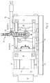
- a basic embodiment of the injection molding machine of the present invention comprising molding stations A and B having essential accessories defining a primary clamp section 11, a secondary clamp section 12, a primary molten plastic injection section 13 and a secondary injection section 14.
- Either the primary and/or secondary injection unit may be of the reciprocating screw type or piston type.
- Molds 16 and 17, frequently of different configurations, comprise mold halves 18 and 19 and 21 and 22, respectively.
- Mold halves 19 and 21 are mounted on central movable platen 26 and halves 18 and 22 are mounted on movable platen 24 and fixed platen 27, respectively.
- Platen 24 is connected to primary clamping piston 32 and is reciprocated thereby sliding on tie bars 28 and 29.
- Central platen 26 is also movable on tie bars 28 and 29 and is releasably connected to movable platen 24 and fixed platen 27 by secondary clamping means 12 in a manner which will be explained in greater detail as this specification proceeds.
- Machine section 14 includes a distribution block 33 incorporated in platen 26, with heating elements 34, molten plastic supply channel 36 and selector valve 37 for diverting compound flow from station A to station B and vice versa.
- the distributor block 33 terminates in a cylinder 38 having a piston 39 and a reservoir 41.
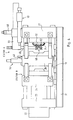
- a second channel 42 adapted to make a connection with a reciprocating primary injection section 13, as is most apparent in Fig. 2, includes a shut off valve 43 for cutting off molten plastic flow from the primary injection means.
- the injection section 13 includes a plasticizing-injection unit referred to in the art as a reciprocating-screw extruder.
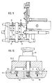
- Figs. 4, 5 and 6 are similar to Figs. 1, 2 and 3 and show details of one embodiment of the secondary clamp means and the structure and operation of the molded parts removal unit or robot.
- the parts removal unit operates automatically in timed sequence, in robot fashion, and includes a first leg 44 which reciprocates under control of power unit 46 along the longitudinal axis (x axis) of the machine guided by a track (not shown).
- the power unit 46 is supported by fixed platen 27.
- a second leg 49 is actuated by suitable power means to advance the head along a second axis (z axis) into register with finished part P.
- the part is then ejected from core 51 by ejector pins 52, in well known fashion, and picked up by the head.
- the head 48 is provided with a source of vacuum and a valve operable to direct vacuum to the part side of the head where upon the part P is grasped and drawn away from the core by the head. The head is retracted automatically and the part P released to an appropriate container (not shown) for packaging or further processing, as the case may be.
- Figs. 5 and 6 are top plan views of the illustration of Fig. 4 and show details and operation of one embodiment of the secondary clamp section indicated generally by the reference numeral 12.
- Pairs of opposed arms 53 and 54, fixed to central platen 26, are formed with notches 56 and 57 and cam faces 58 and 59.
- the notches are engaged by dogs or lugs 61 and 62 having mating cam faces 63 and 64.
- the lugs 61 and 62 operable to reciprocate in timed sequence under the control of piston-cylinder assemblies 66 and 67, are mounted on the movable platen 24 and fixed platen 27, respectively.
- Fig. 6 shows the part removal head 48 in place in the open mold at station B poised to retract from the mold to transfer part P out of the machine.
- a plot showing a typical molding cycle of the machine of Figs. 1 through 6 is laid out coordinately where the y axis is a schedule of sequential positions of the various machine components or accessories for stations A and B, and the x axis is a schedule of the progress of the part through the molding steps.
- the chart is read in the following fashion: starting at the upper left hand corner at the point indicated by the letter S, one "picks up” the molding cycle by noting the small circles extending along the y axis which indicate that primary clamp 11 is open, injection section 13 is back (to the right in Fig.
- the injection section 13 is plasticizing, shut off valve 43 is closed, secondary injection section 14 (stuffer piston 38) is retracted, selector valve 37 is open to station A, secondary clamp section 12 is clamping station A, secondary clamp 12 at station B is free (open), ejector pins 52 are retracted at station A, ejector pins 52 are forward (ejecting) at station B, robot or pick up head 48 has moved along machine x axis to station B and along the z axis into the mold at station B.
- the chart is read in the manner described incrementally from left to right, the machine having produced two parts P upon arriving at end E of a complete cycle.
- FIG. 8 an alternative embodiment of the primary and secondary injection means is disclosed schematically.
- molding stations A and B are serviced by an injection unit 68 and secondary injection unit 69.
- a selector valve 71 (shown as a two way valve but which may be a three way valve) disposed in distributor block 72 within platen 70, is operable to divert the flow of molten plastic from injection unit 68 to the mold at station B as indicated schematically in Fig. 9 or to the mold at station A as indicated schematically in Fig. 10.
- operation of the injection unit in the Fig. 9 arrangement delivers molten plastic simultaneously to the mold of station B and to the secondary injection unit 69.
- selector valve 71 directs the molten plastic to mold station A while injection continues into station B from the secondary injection unit.
- the significance of this arrangement is that (1) the primary injection unit is programmed to prepare sufficient plastic to satisfy the molds of both mold stations A and B; (2) the secondary injection unit 69 completes injection into the mold at station B after selector valve 71 shifts the flow of plastic to station A: (3) molten plastic is delivered directly to station A from the primary injection unit to complete the injection, whereby either the primary and/or secondary unit may serve as a stuffer. For example, as a variation of this embodiment one may also stuff station A with secondary injection unit 69 with appropriate valving.
- Either the primary or secondary injection units may be of the reciprocating screw type or the piston type.
- Injection pressure of molten plastic into a mold cavity to fill a mold cavity is frequently of a level ranging from 15,000 to 21,000 psi and injection pressure to "hold or stuff" the cavity to compensate for shrinkage is frequently of the order of 6,000 psi.
- These pressure levels can be developed by primary and/or secondary injection means.
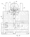
- FIGs. 11 and 12 an alternative design for a secondary clamping unit is disclosed wherein parting line clamp elements 73 and 74 are shown mounted on mold halves 75 as at 76 shown in Figs. 11 and 12.
- the units at station A and station B are of identical structure. Therefore, only one modified secondary clamping unit will be described.
- the clamp elements 73 and 74 are operated by a piston-cylinder arrangement 77 on opposite sides of a mold station such as is shown at stations A and B in Fig. 11.
- Mating mold halves are formed with cut outs or recesses 81 and 82 fitted with hardened inserts 83 and 84 secured to mold halves by bolts 87 and 88.
- Each insert is formed with a taper mating with a corresponding taper on the complementary clamps 73-74.
- Actuation of the cylinder unit 77 moves the clamps on ooposite sides of the molds along a piston rod 86 (fixed to a mold half as at 76) from a retracted position of Fig. 12 to an operating position shown in Fig. 11 driving the mold halves into face to face contact under very high compressive stress.
- parting line clamp structure of Figs. 11 and 12 is mounted directly on the mold halves and operates directly on the mold halves, in contrast to the secondary clamp structure described previously which is mounted on the mold platens and operates directly on the mold platens.
- a further alternative embodiment of the injection molding machine wherein the open mold configuration at station B represents a large, complex part.
- a machine modification is arranged wherein a plurality of primary injection units 91, 92 and 93 are mounted on the top of fixed platen 94.
- Suitable tracks 96 are provided for advancing the injection units to and from to make appropriate connection with mating secondary injection units or stuffers 97, 98 and 99 incorporated in a central movable platen 101.
- the primary injection units and cooperating stuffer units are operable individually or collectively in various combinations and permutations as design complexity of the molded parts dictate.
- Fig. 14 illustrates a double capacity machine in which there are four molding stations A, B, C and D, two opposed primary injection extruders 102 and 103 with two central mold platens 104 and 106 each incorporating a secondary extrusion units or stuffers 107 and 108, in the fashion and for the purpose previously described, for servicing mold stations D and C on the left and mold stations B and A on the right, respectively.
- the reference numerals 109 and 111 designate mold part removal units or robots. Naturally, each mold station could have a plurality of molds as required.
- Fig. 14 shows the molds open at stations A and D while the molds at stations B and C are closed.
- This configuration is developed in the following fashion.
- the piston 32 is ordered to move to the left. This occurrence opens the mold at station A and dog 117 secured to movable platen 25 moves from the dashed line position to the solid line position to abut stop 118.
- the secondary clamp at station D is unlatched so that upon continued motion of the piston 32 to the left the mold at station D opens to complete development of the mold layout shown in Fig. 14, i.e. molds at stations A and D are open and molds at stations B and C remain closed and clamped.
- Fig. 15 is an operating schedule showing the sequential positions of the various machine accessories as the double capacity unit of Fig. 14 operates to produce four molded parts per cycle.
- a modified injection molding machine includes fixed platens 23 and 27 , carried by a base frame supporting pairs of tie bars 28 and 29 in the usual and customary fashion.
- a movable central platen, indicated generally at 136, incorporating a hot runner system comprises a manifold distributor block 120, moldable material switching valve means 121, manifold means defining manifold sections 122 and 123, and mold halves 124 and 126 supported by said central platen 136.
- Central platen 136 is movable in cooperation with movable platen 24 to open and close mold halves at mold stations indicated at A and B to mold articles, such as at G.
- the clamps 128, 129, 131 and 132 operate to seal and maintain close contact between mold halves during molding in controlled sequence.
- manifold sections 122 and 123 straddle and are supported removably by the movable central platen 136.
- manifold sections 122 and 123 are isolated from the central platen 136 by an insulating air gap indicated by the reference numeral 137 .
- Mold halves 124 and 126 are also supported by the central platen 136 and the manifold sections 122 and 123 are sealed against respective mold halves 124 and 126 about the periphery of mold openings 138 by seal means defining a raised annulus or boss as indicated by the reference numerals 100 and 101.
- Manifold distributor block 120 connected to the central platen 136, includes molding material switching valve 121 and provides support for an injection unit nozzle clamping means indicated generally by the reference numeral 142.
- An injection unit in the form of an extruder 143 movably supported by means (not shown), is movable from the position shown in Fig. 20 to an injection position indicated in Fig. 21, along a path or axis indicated by the reference numeral 144.
- the axis 144 is generally parallel to the injection molding machine axis (mold clamping axis) indicated by the reference numeral 146.
- nozzle 147 is aligned with and communicates with orifice 148 of manifold distributor block 120.
- a seal is effected by the contact between surface 149 of manifold distributor block insert 151 and surface 152 of nozzle insert 153.
- nozzle clamping means 142 defining, in this embodiment of the invention, cylinder 154 with cooperating piston 156 secured to the manifold distributor block 120 by rods 157.
- the nozzle clamping means acts along axis 160, which is perpendicular to machine or clamping axis 146.
- Switching valve means 121 upstream of the manifold means, defining a spool valve is operated in cyclic fashion in synchronism with the molding cycle to switch moldable material to appropriate manifold section 122 and 123 via conduits 133 and 134 (Fig. 23).
- the spool valve 121 is reciprocated by valve operating cylinder 159 (Fig. 22), as indicated by the arrow 161 of Fig. 23.
- Ball check valve 162 is provided in moldable material flow path 163 to prevent leakage when the nozzle is unclamped and the seal between the nozzle and the manifold distributor block is broken.
- a stuffer or packer unit 164 is located upstream of the spool valve 121 and communicates with the flow path 163 via conduit 166.
- the injection position will vary along the machine axis depending upon the dimensions of the mold halves in the closed position measured along the longitudinal or clamping axis of the machine.
- the stroke of the injection unit is also advantageous in that it provides access for a robot or other automatic molded article retrieval device to enter open mold halves to grasp and remove a molded article C.
Landscapes
- Engineering & Computer Science (AREA)
- Manufacturing & Machinery (AREA)
- Mechanical Engineering (AREA)
- Robotics (AREA)
- Injection Moulding Of Plastics Or The Like (AREA)
- Moulds For Moulding Plastics Or The Like (AREA)
- Diaphragms For Electromechanical Transducers (AREA)
- Processing And Handling Of Plastics And Other Materials For Molding In General (AREA)
Claims (15)
- Machine à mouler par injection destinée à mouler des pièces en matière plastique (6), comportant un châssis de machine (31) comprenant :
au moins deux postes de moulage (A, B, C, D) formés par une pluralité de moules séparables et amovibles (16, 17) portés par une pluralité de platines mobiles (24, 26, 70, 101, 104, 106, 136),
au moins un moyen d'injection (13, 14, 68, 91, 93, 97, 98, 99, 102, 103, 107, 108, 143, 164) servant à injecter de la matière plastique fondue dans les moules (16, 17),
des conduits d'alimentation en matière plastique fondue (36, 42) communiquant avec au moins un moule (16, 17),
des moyens de commande pour actionner sélectivement et séquentiellement les moyens d'injection (13, 14, 68, 91, 92, 93, 97, 98, 99, 102, 103, 107, 108, 143, 164) de manière à faire avancer la matière plastique fondue vers les moules (16,17) par l'intermédiaire des conduits d'alimentation (36, 42), vers des moules sélectionnés (16, 17) à des emplacements de moule sélectionnés
des moyens de blocage (11, 12) servant à fermer et à bloquer les moules (16, 17),
des moyens pour supprimer la force de blocage appliquée aux moules (16, 17) indépendamment les uns de autres, et
des moyens (44 à 49, 109, 111) pour retirer les pièces moulées (G),
caractérisée en ce que,
les conduits d'alimentation (36, 42) sont disposés dans un bloc distributeur (33, 72, 120) qui est introduit de manière amovible dans une platine centrale mobile séparée (26, 70, 101, 104, 106, 136) entre les deux moules (16, 17) portant une moitié de moule (19, 21, 124, 126) de chaque côté, et en ce qu'on utilise des moyens d'injection primaire et secondaire (13, 14 ; 68, 69 ; 91, 92, 93, 97, 98, 99 ; 102, 103, 107, 108 ; 143, 164) dans lesquels le moyen d'injection secondaire (14, 69, 97, 98, 99, 107, 108, 164) sert à remplir complètement au moins un moule (16, 17). - Machine selon la revendication 1, caractérisée en ce que le moyen d'injection primaire est une extrudeuse mobile et le moyen d'injection secondaire est un mécanisme de remplissage fixé au bloc de distributeur (33, 72, 120).
- Machine selon les revendications 1 ou 2, caractérisée en ce qu'une pluralité de moyens de soupape (37, 43, 71, 121) sont utilisés dans le bloc distributeur (33, 72, 120),
un premier moyen de soupape (37, 71, 121) servant à commander sélectivement le débit de matière plastique fondue du premier moule (16) vers un second moule (17), et
un second moyen de soupape (43) servant à commuter sélectivement le débit de matière plastique fondue de l'un des moyens d'injection (13, 14, 68, 69, 91, 92, 93, 97, 98, 99 ; 102, 103, 107, 108 ; 143, 164) pour assurer de manière cyclique l'introduction et le maintien d'une quantité de matière plastique adéquate dans chaque moule (16, 17). - Machine selon l'une des revendications 1 à 3, caractérisée en ce que la platine centrale (136) est supportée par des tiges de liaison (28, 29) et peut aller et venir le long de ces tiges (28, 29) pour définir un premier axe (146), et la platine centrale (136) comprend un système de coulée à chaud manoeuvrable pour se relier au bloc d'injection (143) qui est bloqué sur ce système de coulée à chaud,
le système de coulée à chaud comprend le bloc de distributeur (120) communiquant avec un moyen de tubulure,
le moyen de tubulure est monté sur l'extérieur de la platine centrale (136) en étant supporté par celle-ci, et définit deux sections de tubulure indépendantes séparées (122, 123) enjambant la platine centrale (136). - Machine selon la revendication 4, caractérisée par un moyen de soupape (121) monté dans le bloc distributeur (120) en amont du moyen de tubulure pour diriger sélectivement le matériau moulable vers les sections de tubulure (122, 123).
- Machine selon la revendication 4 ou 5, caractérisée par des moyens d'étanchéité (S-1) montés en coopération sur le système de coulée à chaud et sur le moyen d'injection (143) pour former un joint d'étanchéité entre le système de coulée à chaud et le moyen d'injection (143), des moyens d'assistance à moteur (142) effectuant une action de blocage le long d'un second axe (160) généralement perpendiculaire au premier axe (146).
- Machine selon l'une des revendications 4 à 6, caractérisée en ce que le moyen d'injection (143) comprend une buse (147), en ce que le système de coulée à chaud comporte un orifice de raccordement (148), et en ce que le moyen d'assistance à moteur fonctionne pour bloquer la buse (147) sur l'orifice (148), de manière amovible, le long d'un second axe (160) généralement perpendiculaire au premier axe (146).
- Machine selon l'une au moins des revendications 4 à 7, caractérisée en ce que le moyen d'injection (143) comprend une extrudeuse qui fait avancer le matériau moulable le long d'un chemin (144) parallèle au premier axe (146), et en ce que la buse (147) fait avancer le matériau le long d'un chemin parallèle au second axe (160).
- Machine selon l'une au moins des revendications 4 à 8, caractérisée en ce que la platine centrale (136) supporte des moitiés de moule amovibles (124, 126) communiquant chacune avec une section de tubulure adjacente (122, 123), ces moitiés de moule (124, 126) étant interchangeables pour s'adapter à la forme et à la taille des articles (G) à mouler, de sorte que la platine centrale (136) reste une pièce fixe de la machine.
- Machine selon l'une au moins des revendications 4 à 9, caractérisée en ce que le moyen d'injection (143) peut se déplacer sur une course bien définie le long d'un chemin (144) parallèle au premier axe (146), pour passer d'une première position dans laquelle le moyen (143) est dégagé du système de coulée à chaud, à une seconde position dans laquelle le moyen (143) est aligné avec le système de coulée à chaud, le moyen d'assistance à moteur (142) étant actionnable le long d'un second axe (160) pour bloquer et sceller le moyen d'injection (143) sur le système de coulée à chaud, le premier axe et le second axe (146, 160) étant généralement perpendiculaires.
- Machine selon l'une au moins des revendications 4 à 10, caractérisée en ce que le système de coulée à chaud comprend un clapet de retenue (162) pour éviter une fuite du matériau de moulage hors du système de coulée à chaud lorsque le moyen d'injection (143) ne se trouve pas dans le mode d'étanchéité.
- Machine selon l'une au moins des revendications 4 à 11, caractérisée en ce que le moyen de remplissage ou de bourrage (164) est relié au bloc distributeur (120), et en ce que le moyen de soupape (121) est actionnable sélectivement pour relier le moyen d'injection (143) exclusivement au moyen de bourrage (164).
- Machine selon l'une au moins des revendications 4 à 12, caractérisée en ce que le bloc de distributeur (120) et chaque section de tubulure (122, 123) respective, sont complètement isolés de la platine centrale (136) par un intervalle d'air d'isolation (137).
- Machine selon l'une au moins des revendications 4 à 13, caractérisée en ce que la platine centrale (136) supporte un moyen de bourrage de moule actionnable pour assurer la communication avec le système de coulée à chaud, de manière à fournir du matériau moulable indépendamment des moyens d'injection.
- Procédé pour mouler des pièces en matière plastique en utilisant une machine à mouler par injection selon l'une au moins des revendications 1 à 14, procédé caractérisé en ce qu'il consiste à :- fermer et bloquer les moules (16, 17),- injecter de la matière plastique fondue dans le premier moule bloqué (16) pour remplir ce moule,- maintenir la pression dans le premier moule (16) après le remplissage et pendant le refroidissement, en utilisant la pression du moyen d'injection primaire (13, 68, 91, 92, 93, 102, 103, 143),- injecter de la matière plastique fondue dans le second moule bloqué (17) pour remplir ce moule,- maintenir la pression dans le second moule (17) après le remplissage et pendant le refroidissement, en utilisant la pression du moyen d'injection secondaire (14, 69, 97, 98, 99, 107, 108, 164),- refroidir la matière plastique fondue dans les deux moules (16, 17), débloquer et ouvrir les moules, et- retirer les pièces moulées (G).
Priority Applications (1)
| Application Number | Priority Date | Filing Date | Title |
|---|---|---|---|
| EP93118130A EP0589489B1 (fr) | 1988-01-29 | 1989-01-28 | Machine à mouler par injection séquentielle |
Applications Claiming Priority (4)
| Application Number | Priority Date | Filing Date | Title |
|---|---|---|---|
| US150157 | 1988-01-29 | ||
| US07150157 US4867938B1 (en) | 1988-01-29 | 1988-01-29 | Sequential injection molding process |
| US07/294,308 US4981638A (en) | 1988-01-29 | 1989-01-06 | Method and apparatus for clamping an injection unit to a molding machine |
| US294308 | 2001-05-30 |
Related Child Applications (2)
| Application Number | Title | Priority Date | Filing Date |
|---|---|---|---|
| EP93118130A Division EP0589489B1 (fr) | 1988-01-29 | 1989-01-28 | Machine à mouler par injection séquentielle |
| EP93118130.9 Division-Into | 1993-11-09 |
Publications (3)
| Publication Number | Publication Date |
|---|---|
| EP0326175A2 EP0326175A2 (fr) | 1989-08-02 |
| EP0326175A3 EP0326175A3 (fr) | 1991-06-12 |
| EP0326175B1 true EP0326175B1 (fr) | 1995-03-29 |
Family
ID=26847366
Family Applications (2)
| Application Number | Title | Priority Date | Filing Date |
|---|---|---|---|
| EP93118130A Expired - Lifetime EP0589489B1 (fr) | 1988-01-29 | 1989-01-28 | Machine à mouler par injection séquentielle |
| EP89101507A Expired - Lifetime EP0326175B1 (fr) | 1988-01-29 | 1989-01-28 | Machine à mouler par injection séquentielle |
Family Applications Before (1)
| Application Number | Title | Priority Date | Filing Date |
|---|---|---|---|
| EP93118130A Expired - Lifetime EP0589489B1 (fr) | 1988-01-29 | 1989-01-28 | Machine à mouler par injection séquentielle |
Country Status (7)
| Country | Link |
|---|---|
| US (1) | US4981638A (fr) |
| EP (2) | EP0589489B1 (fr) |
| JP (1) | JPH0790574B2 (fr) |
| AT (2) | ATE153904T1 (fr) |
| CA (1) | CA1315507C (fr) |
| DE (2) | DE68921902T2 (fr) |
| ES (2) | ES2105047T3 (fr) |
Families Citing this family (19)
| Publication number | Priority date | Publication date | Assignee | Title |
|---|---|---|---|---|
| US5011646A (en) * | 1989-02-24 | 1991-04-30 | Husky Injection Molding Systems Ltd. | Method and apparatus for injection molding using a movable sprue bar |
| US4983117A (en) * | 1989-12-26 | 1991-01-08 | Husky Injection Molding Systems Ltd. | Anti-drool injection molding apparatus |
| US5040969A (en) * | 1990-01-26 | 1991-08-20 | Husky Injection Molding Systems Ltd. | Tandem injection molding machine with direct feed to molds |
| ITBS940068A1 (it) * | 1994-06-10 | 1995-12-11 | Supply Srl | Macchina per lo stampaggio di materie plastiche con piu' stampi e un singolo gruppo di iniezione |
| US5849236A (en) * | 1996-05-10 | 1998-12-15 | Siegel-Robert, Inc. | Method and apparatus for plastic injection molding flow control |
| FR2760677A1 (fr) * | 1996-09-06 | 1998-09-18 | Anteq | Equipement pour la commande de busettes d'injection d'une presse d'injection sequentielle |
| US6117924A (en) * | 1996-10-22 | 2000-09-12 | Crane Plastics Company Limited Partnership | Extrusion of synthetic wood material |
| ES2148038B1 (es) * | 1997-06-30 | 2001-04-16 | Padilla Jose Santoyo | Procedimiento de desplazamiento lateral de inyectores de preformas termoplasticas. |
| US5935504A (en) * | 1998-01-26 | 1999-08-10 | Gemtron Corporation | Method for substituting horizontally and vertically opening molds |
| US6837699B2 (en) * | 2002-03-14 | 2005-01-04 | John Jandura | Method and apparatus for clamping used in molding applications |
| EP1759826B1 (fr) * | 2004-06-10 | 2013-12-04 | Toyota Jidosha Kabushiki Kaisha | Dispositif de canal chauffé et dispositif de moulage par injection |
| EP2100678B1 (fr) * | 2008-03-11 | 2013-12-25 | Georg Fischer Automotive (Suzhou) Co. Ltd | Outil de coulée sous pression d'une machine de coulée sous pression |
| KR100955480B1 (ko) * | 2009-03-12 | 2010-04-30 | 삼성전자주식회사 | 디스플레이장치용 지지장치 및 이를 포함하는 디스플레이장치 |
| JP5030116B2 (ja) * | 2010-04-27 | 2012-09-19 | 株式会社名機製作所 | 複合成形品用射出成形機およびその成形方法 |
| WO2012092658A1 (fr) * | 2011-01-09 | 2012-07-12 | Husky Injection Molding Systems Ltd. | Ensemble de distribution de matière fondue comprenant un ensemble bâti positionné à l'extérieur d'une enveloppe à plateau et possédant un ensemble à multiples orifices de sortie |
| JP5633983B2 (ja) * | 2013-07-03 | 2014-12-03 | 株式会社名機製作所 | 複合成形品の射出成形機およびその作動方法 |
| CN109159353A (zh) * | 2018-08-06 | 2019-01-08 | 华东交通大学 | 一种生物工程用基因培养皿加工用冷却脱模装置 |
| CN110406028B (zh) * | 2019-07-19 | 2021-01-08 | 龙家钊 | 一种汽车调温器罩体注塑成型模具 |
| CN113787673A (zh) * | 2021-07-23 | 2021-12-14 | 海天塑机集团有限公司 | 一种用于模具配对生产的注射成型方法与系统 |
Family Cites Families (28)
| Publication number | Priority date | Publication date | Assignee | Title |
|---|---|---|---|---|
| JPS497065B1 (fr) * | 1964-11-20 | 1974-02-18 | ||
| FR1432150A (fr) * | 1965-04-23 | 1966-03-18 | Installation-transfert, notamment table tournante automatique, pour le travail des matières thermoplastiques et du caoutchouc | |
| NL7202930A (fr) * | 1971-03-15 | 1972-09-19 | ||
| NL7112642A (fr) * | 1971-09-14 | 1973-03-16 | ||
| US3973892A (en) * | 1972-01-17 | 1976-08-10 | Husky Injection Molding Systems | Injection-molding machine with transverse feed |
| US3898030A (en) * | 1973-06-25 | 1975-08-05 | Koehring Co | Injection-mold clamping unit having alternately ejecting die assemblies |
| FR2297719A1 (fr) * | 1975-01-16 | 1976-08-13 | Rollin Jean | Perfectionnements aux robots industriels |
| NO753485L (fr) * | 1975-10-31 | 1976-05-03 | Bone Cravens Ltd | |
| CH625461A5 (en) * | 1977-12-15 | 1981-09-30 | Netstal Ag Maschf Giesserei | Injection moulding machine with multi-daylight mould for plasticatable compositions |
| US4400341A (en) * | 1980-10-14 | 1983-08-23 | Universal Commerce And Finance N.V. | Injection molding of thermoplastics in sandwich mold employing desynchronized opening, extended and closing periods |
| JPS58166030A (ja) * | 1982-03-26 | 1983-10-01 | Shoichi Teraoka | 金型多段重ね合せ式射出成形機 |
| EP0103363B1 (fr) * | 1982-07-15 | 1986-11-26 | SORENSEN, Jens Ole | Moulage non synchrone par injection à plusieurs étages |
| JPS60141515A (ja) * | 1983-12-28 | 1985-07-26 | Toshiba Mach Co Ltd | 多色射出成形機 |
| JPS61193817A (ja) * | 1985-02-22 | 1986-08-28 | Shoichi Teraoka | 減圧ロツドをもつたtダイに複数ノズルを配置し多段取用金型に減圧力を付加させて小物品多数取り金型に高能率射出する成形機とその成形方法 |
| JPS629923A (ja) * | 1985-07-08 | 1987-01-17 | Shoichi Teraoka | 重ね取り金型を用いる成形法とこれに用いるノズル装置 |
| JPS6235817A (ja) * | 1985-08-09 | 1987-02-16 | Shoichi Teraoka | 中間可動盤とこれに嵌合されるホツトランナ−マニホ−ルドと重ね取り金型装置とこの側面に併行して射出ユニツトを配置した射出成形機 |
| DE3529775A1 (de) * | 1985-08-20 | 1987-03-12 | Fahr Bucher Gmbh | Vorrichtung zur herstellung von formteilen |
| DE3532299A1 (de) * | 1985-09-11 | 1987-03-19 | Battenfeld Kunststoffmasch | Spritzgiessmaschine mit spritzling-entnahmevorrichtung |
| DE3532300C1 (de) * | 1985-09-11 | 1987-01-08 | Battenfeld Kunststoffmasch | Spritzling-Entnahmevorrichtung fuer Spritzgiessmaschinen |
| JPS6262722A (ja) * | 1985-09-12 | 1987-03-19 | Toyoda Gosei Co Ltd | 樹脂成形品の離形取出装置 |
| US4793796A (en) * | 1985-09-26 | 1988-12-27 | Kaaden Hans Heinrich | Apparatus for the manufacture of plastic parts by injection molding or reaction injection molding |
| KR870003859A (ko) * | 1985-10-16 | 1987-05-04 | 카아덴 한스-하인릭히 | 다이캐스팅 방법 또는 반동다이캐스팅 방법으로 합성수지 부품의 제조를 위한 다이캐스팅 기계 |
| JPH0346897Y2 (fr) * | 1985-11-29 | 1991-10-04 | ||
| DE3544155A1 (de) * | 1985-12-13 | 1987-07-02 | Stuebbe Gmbh Maschf | Spritzgiessmaschine zum herstellen von kunststoffteilen im spritzgiess- oder reaktionsspritzgiessverfahren |
| JPS62236717A (ja) * | 1986-04-07 | 1987-10-16 | Ube Ind Ltd | 射出成形機 |
| JPS62273816A (ja) * | 1986-05-23 | 1987-11-27 | Sumitomo Heavy Ind Ltd | 射出成形品の自動取出し装置 |
| JPS634923A (ja) * | 1986-06-26 | 1988-01-09 | Sumitomo Heavy Ind Ltd | 射出成形機等の成形品自動取出装置 |
| EP0370050B1 (fr) * | 1987-07-08 | 1994-05-18 | Primtec | Commande de pression et serrage dans un systeme de moulage a plusieurs parties empilees a periodes d'injection desynchronisees |
-
1989
- 1989-01-06 US US07/294,308 patent/US4981638A/en not_active Expired - Lifetime
- 1989-01-27 CA CA000589420A patent/CA1315507C/fr not_active Expired - Fee Related
- 1989-01-27 JP JP1016483A patent/JPH0790574B2/ja not_active Expired - Lifetime
- 1989-01-28 DE DE68921902T patent/DE68921902T2/de not_active Expired - Fee Related
- 1989-01-28 EP EP93118130A patent/EP0589489B1/fr not_active Expired - Lifetime
- 1989-01-28 ES ES93118130T patent/ES2105047T3/es not_active Expired - Lifetime
- 1989-01-28 AT AT93118130T patent/ATE153904T1/de not_active IP Right Cessation
- 1989-01-28 AT AT89101507T patent/ATE120398T1/de active
- 1989-01-28 EP EP89101507A patent/EP0326175B1/fr not_active Expired - Lifetime
- 1989-01-28 DE DE68928109T patent/DE68928109T2/de not_active Expired - Fee Related
- 1989-01-28 ES ES89101507T patent/ES2070863T3/es not_active Expired - Lifetime
Also Published As
| Publication number | Publication date |
|---|---|
| EP0326175A2 (fr) | 1989-08-02 |
| ATE153904T1 (de) | 1997-06-15 |
| EP0589489B1 (fr) | 1997-06-04 |
| ES2070863T3 (es) | 1995-06-16 |
| ES2105047T3 (es) | 1997-10-16 |
| ATE120398T1 (de) | 1995-04-15 |
| DE68921902T2 (de) | 1995-07-27 |
| DE68928109T2 (de) | 1997-09-18 |
| CA1315507C (fr) | 1993-04-06 |
| JPH01308609A (ja) | 1989-12-13 |
| DE68928109D1 (de) | 1997-07-10 |
| JPH0790574B2 (ja) | 1995-10-04 |
| EP0589489A2 (fr) | 1994-03-30 |
| US4981638A (en) | 1991-01-01 |
| EP0326175A3 (fr) | 1991-06-12 |
| EP0589489A3 (en) | 1994-05-11 |
| DE68921902D1 (de) | 1995-05-04 |
Similar Documents
| Publication | Publication Date | Title |
|---|---|---|
| US4867938A (en) | Sequential injection molding process | |
| EP0326175B1 (fr) | Machine à mouler par injection séquentielle | |
| US5185119A (en) | Injection molding process | |
| EP0246512B1 (fr) | Co-injection d'articles creux et préformes | |
| US9802351B2 (en) | Molding apparatus | |
| EP0108333B1 (fr) | Presse à mouler par injection | |
| EP0475243B1 (fr) | Moule à plateaux avec un canal isolant | |
| US5112558A (en) | Injection molding process | |
| EP0393389B1 (fr) | Pot de transfert étagé pour le moulage par injection | |
| EP0947303B1 (fr) | Dispositif d'entraînement pour pot d'injection pour une machine à mouler par injection | |
| US5052915A (en) | Sequential injection molding machine | |
| EP0873840B1 (fr) | Machine à mouler par injection pour la fabrication d'articles creux en matière plastique | |
| EP0438721B1 (fr) | Machine à mouler par injection en tandem avec alimentation directe des moules | |
| US3289252A (en) | Machine for molding bottle carrying cases | |
| US5833899A (en) | Method for the preparation of method articles by single and multi-layer compression and apparatus therefor | |
| US5055250A (en) | Injection molding process | |
| US3773450A (en) | Arrangement at injection moulding machine for rendering possible multi-component moulding | |
| US5073328A (en) | Injection molding process | |
| CA1328721C (fr) | Machine de moulage par injections sequentielles | |
| EP0103363B1 (fr) | Moulage non synchrone par injection à plusieurs étages | |
| EP0724514A1 (fr) | Machine de moulage par injection verticale |
Legal Events
| Date | Code | Title | Description |
|---|---|---|---|
| PUAI | Public reference made under article 153(3) epc to a published international application that has entered the european phase |
Free format text: ORIGINAL CODE: 0009012 |
|
| AK | Designated contracting states |
Kind code of ref document: A2 Designated state(s): AT BE CH DE ES FR GB GR IT LI LU NL SE |
|
| PUAL | Search report despatched |
Free format text: ORIGINAL CODE: 0009013 |
|
| AK | Designated contracting states |
Kind code of ref document: A3 Designated state(s): AT BE CH DE ES FR GB GR IT LI LU NL SE |
|
| 17P | Request for examination filed |
Effective date: 19910626 |
|
| 17Q | First examination report despatched |
Effective date: 19920708 |
|
| GRAA | (expected) grant |
Free format text: ORIGINAL CODE: 0009210 |
|
| AK | Designated contracting states |
Kind code of ref document: B1 Designated state(s): AT BE CH DE ES FR GB GR IT LI LU NL SE |
|
| PG25 | Lapsed in a contracting state [announced via postgrant information from national office to epo] |
Ref country code: IT Free format text: LAPSE BECAUSE OF FAILURE TO SUBMIT A TRANSLATION OF THE DESCRIPTION OR TO PAY THE FEE WITHIN THE PRE;WARNING: LAPSES OF ITALIAN PATENTS WITH EFFECTIVE DATE BEFORE 2007 MAY HAVE OCCURRED AT ANY TIME BEFORE 2007. THE CORRECT EFFECTIVE DATE MAY BE DIFFERENT FROM THE ONE RECORDED.SCRIBED TIME-LIMIT Effective date: 19950329 Ref country code: GR Free format text: LAPSE BECAUSE OF FAILURE TO SUBMIT A TRANSLATION OF THE DESCRIPTION OR TO PAY THE FEE WITHIN THE PRESCRIBED TIME-LIMIT Effective date: 19950329 Ref country code: BE Effective date: 19950329 |
|
| REF | Corresponds to: |
Ref document number: 120398 Country of ref document: AT Date of ref document: 19950415 Kind code of ref document: T |
|
| XX | Miscellaneous (additional remarks) |
Free format text: TEILANMELDUNG 93118130.9 EINGEREICHT AM 09/11/93. |
|
| ET | Fr: translation filed | ||
| REF | Corresponds to: |
Ref document number: 68921902 Country of ref document: DE Date of ref document: 19950504 |
|
| REG | Reference to a national code |
Ref country code: ES Ref legal event code: FG2A Ref document number: 2070863 Country of ref document: ES Kind code of ref document: T3 |
|
| PG25 | Lapsed in a contracting state [announced via postgrant information from national office to epo] |
Ref country code: SE Effective date: 19950629 |
|
| PLBE | No opposition filed within time limit |
Free format text: ORIGINAL CODE: 0009261 |
|
| STAA | Information on the status of an ep patent application or granted ep patent |
Free format text: STATUS: NO OPPOSITION FILED WITHIN TIME LIMIT |
|
| 26N | No opposition filed | ||
| PGFP | Annual fee paid to national office [announced via postgrant information from national office to epo] |
Ref country code: LU Payment date: 19971215 Year of fee payment: 10 |
|
| PGFP | Annual fee paid to national office [announced via postgrant information from national office to epo] |
Ref country code: FR Payment date: 19980109 Year of fee payment: 10 |
|
| PGFP | Annual fee paid to national office [announced via postgrant information from national office to epo] |
Ref country code: AT Payment date: 19980114 Year of fee payment: 10 |
|
| PGFP | Annual fee paid to national office [announced via postgrant information from national office to epo] |
Ref country code: GB Payment date: 19980119 Year of fee payment: 10 |
|
| PGFP | Annual fee paid to national office [announced via postgrant information from national office to epo] |
Ref country code: NL Payment date: 19980128 Year of fee payment: 10 |
|
| PGFP | Annual fee paid to national office [announced via postgrant information from national office to epo] |
Ref country code: ES Payment date: 19980129 Year of fee payment: 10 |
|
| PGFP | Annual fee paid to national office [announced via postgrant information from national office to epo] |
Ref country code: CH Payment date: 19980205 Year of fee payment: 10 |
|
| PGFP | Annual fee paid to national office [announced via postgrant information from national office to epo] |
Ref country code: DE Payment date: 19980206 Year of fee payment: 10 |
|
| PG25 | Lapsed in a contracting state [announced via postgrant information from national office to epo] |
Ref country code: AT Free format text: LAPSE BECAUSE OF NON-PAYMENT OF DUE FEES Effective date: 19990128 Ref country code: LU Free format text: LAPSE BECAUSE OF NON-PAYMENT OF DUE FEES Effective date: 19990128 Ref country code: GB Free format text: LAPSE BECAUSE OF NON-PAYMENT OF DUE FEES Effective date: 19990128 |
|
| PG25 | Lapsed in a contracting state [announced via postgrant information from national office to epo] |
Ref country code: ES Free format text: THE PATENT HAS BEEN ANNULLED BY A DECISION OF A NATIONAL AUTHORITY Effective date: 19990129 |
|
| PG25 | Lapsed in a contracting state [announced via postgrant information from national office to epo] |
Ref country code: LI Free format text: LAPSE BECAUSE OF NON-PAYMENT OF DUE FEES Effective date: 19990131 Ref country code: CH Free format text: LAPSE BECAUSE OF NON-PAYMENT OF DUE FEES Effective date: 19990131 |
|
| PG25 | Lapsed in a contracting state [announced via postgrant information from national office to epo] |
Ref country code: NL Free format text: LAPSE BECAUSE OF NON-PAYMENT OF DUE FEES Effective date: 19990801 |
|
| GBPC | Gb: european patent ceased through non-payment of renewal fee |
Effective date: 19990128 |
|
| REG | Reference to a national code |
Ref country code: CH Ref legal event code: PL |
|
| PG25 | Lapsed in a contracting state [announced via postgrant information from national office to epo] |
Ref country code: FR Free format text: LAPSE BECAUSE OF NON-PAYMENT OF DUE FEES Effective date: 19990930 |
|
| PG25 | Lapsed in a contracting state [announced via postgrant information from national office to epo] |
Ref country code: DE Free format text: LAPSE BECAUSE OF NON-PAYMENT OF DUE FEES Effective date: 19991103 |
|
| REG | Reference to a national code |
Ref country code: FR Ref legal event code: ST |
|
| REG | Reference to a national code |
Ref country code: ES Ref legal event code: FD2A Effective date: 20010604 |