EP0326274A2 - Kupplungssteuerung für ein Kraftfahrzeug - Google Patents
Kupplungssteuerung für ein Kraftfahrzeug Download PDFInfo
- Publication number
- EP0326274A2 EP0326274A2 EP89300427A EP89300427A EP0326274A2 EP 0326274 A2 EP0326274 A2 EP 0326274A2 EP 89300427 A EP89300427 A EP 89300427A EP 89300427 A EP89300427 A EP 89300427A EP 0326274 A2 EP0326274 A2 EP 0326274A2
- Authority
- EP
- European Patent Office
- Prior art keywords
- clutch
- clutch plate
- signal
- transmission
- speed
- Prior art date
- Legal status (The legal status is an assumption and is not a legal conclusion. Google has not performed a legal analysis and makes no representation as to the accuracy of the status listed.)
- Withdrawn
Links
Images


Classifications
-
- B—PERFORMING OPERATIONS; TRANSPORTING
- B60—VEHICLES IN GENERAL
- B60W—CONJOINT CONTROL OF VEHICLE SUB-UNITS OF DIFFERENT TYPE OR DIFFERENT FUNCTION; CONTROL SYSTEMS SPECIALLY ADAPTED FOR HYBRID VEHICLES; ROAD VEHICLE DRIVE CONTROL SYSTEMS FOR PURPOSES NOT RELATED TO THE CONTROL OF A PARTICULAR SUB-UNIT
- B60W10/00—Conjoint control of vehicle sub-units of different type or different function
- B60W10/04—Conjoint control of vehicle sub-units of different type or different function including control of propulsion units
- B60W10/06—Conjoint control of vehicle sub-units of different type or different function including control of propulsion units including control of combustion engines
-
- B—PERFORMING OPERATIONS; TRANSPORTING
- B60—VEHICLES IN GENERAL
- B60W—CONJOINT CONTROL OF VEHICLE SUB-UNITS OF DIFFERENT TYPE OR DIFFERENT FUNCTION; CONTROL SYSTEMS SPECIALLY ADAPTED FOR HYBRID VEHICLES; ROAD VEHICLE DRIVE CONTROL SYSTEMS FOR PURPOSES NOT RELATED TO THE CONTROL OF A PARTICULAR SUB-UNIT
- B60W10/00—Conjoint control of vehicle sub-units of different type or different function
- B60W10/02—Conjoint control of vehicle sub-units of different type or different function including control of driveline clutches
-
- B—PERFORMING OPERATIONS; TRANSPORTING
- B60—VEHICLES IN GENERAL
- B60W—CONJOINT CONTROL OF VEHICLE SUB-UNITS OF DIFFERENT TYPE OR DIFFERENT FUNCTION; CONTROL SYSTEMS SPECIALLY ADAPTED FOR HYBRID VEHICLES; ROAD VEHICLE DRIVE CONTROL SYSTEMS FOR PURPOSES NOT RELATED TO THE CONTROL OF A PARTICULAR SUB-UNIT
- B60W10/00—Conjoint control of vehicle sub-units of different type or different function
- B60W10/10—Conjoint control of vehicle sub-units of different type or different function including control of change-speed gearings
- B60W10/101—Infinitely variable gearings
-
- B—PERFORMING OPERATIONS; TRANSPORTING
- B60—VEHICLES IN GENERAL
- B60W—CONJOINT CONTROL OF VEHICLE SUB-UNITS OF DIFFERENT TYPE OR DIFFERENT FUNCTION; CONTROL SYSTEMS SPECIALLY ADAPTED FOR HYBRID VEHICLES; ROAD VEHICLE DRIVE CONTROL SYSTEMS FOR PURPOSES NOT RELATED TO THE CONTROL OF A PARTICULAR SUB-UNIT
- B60W30/00—Purposes of road vehicle drive control systems not related to the control of a particular sub-unit, e.g. of systems using conjoint control of vehicle sub-units
- B60W30/18—Propelling the vehicle
- B60W30/19—Improvement of gear change, e.g. by synchronisation or smoothing gear shift
-
- F—MECHANICAL ENGINEERING; LIGHTING; HEATING; WEAPONS; BLASTING
- F16—ENGINEERING ELEMENTS AND UNITS; GENERAL MEASURES FOR PRODUCING AND MAINTAINING EFFECTIVE FUNCTIONING OF MACHINES OR INSTALLATIONS; THERMAL INSULATION IN GENERAL
- F16D—COUPLINGS FOR TRANSMITTING ROTATION; CLUTCHES; BRAKES
- F16D48/00—External control of clutches
- F16D48/06—Control by electric or electronic means, e.g. of fluid pressure
- F16D48/08—Regulating clutch take-up on starting
-
- F—MECHANICAL ENGINEERING; LIGHTING; HEATING; WEAPONS; BLASTING
- F16—ENGINEERING ELEMENTS AND UNITS; GENERAL MEASURES FOR PRODUCING AND MAINTAINING EFFECTIVE FUNCTIONING OF MACHINES OR INSTALLATIONS; THERMAL INSULATION IN GENERAL
- F16H—GEARING
- F16H61/00—Control functions within control units of change-speed- or reversing-gearings for conveying rotary motion ; Control of exclusively fluid gearing, friction gearing, gearings with endless flexible members or other particular types of gearing
- F16H61/66—Control functions within control units of change-speed- or reversing-gearings for conveying rotary motion ; Control of exclusively fluid gearing, friction gearing, gearings with endless flexible members or other particular types of gearing specially adapted for continuously variable gearings
- F16H61/662—Control functions within control units of change-speed- or reversing-gearings for conveying rotary motion ; Control of exclusively fluid gearing, friction gearing, gearings with endless flexible members or other particular types of gearing specially adapted for continuously variable gearings with endless flexible members
- F16H61/66254—Control functions within control units of change-speed- or reversing-gearings for conveying rotary motion ; Control of exclusively fluid gearing, friction gearing, gearings with endless flexible members or other particular types of gearing specially adapted for continuously variable gearings with endless flexible members controlling of shifting being influenced by a signal derived from the engine and the main coupling
- F16H61/66259—Control functions within control units of change-speed- or reversing-gearings for conveying rotary motion ; Control of exclusively fluid gearing, friction gearing, gearings with endless flexible members or other particular types of gearing specially adapted for continuously variable gearings with endless flexible members controlling of shifting being influenced by a signal derived from the engine and the main coupling using electrical or electronical sensing or control means
-
- B—PERFORMING OPERATIONS; TRANSPORTING
- B60—VEHICLES IN GENERAL
- B60W—CONJOINT CONTROL OF VEHICLE SUB-UNITS OF DIFFERENT TYPE OR DIFFERENT FUNCTION; CONTROL SYSTEMS SPECIALLY ADAPTED FOR HYBRID VEHICLES; ROAD VEHICLE DRIVE CONTROL SYSTEMS FOR PURPOSES NOT RELATED TO THE CONTROL OF A PARTICULAR SUB-UNIT
- B60W2510/00—Input parameters relating to a particular sub-units
- B60W2510/06—Combustion engines, Gas turbines
- B60W2510/0604—Throttle position
-
- B—PERFORMING OPERATIONS; TRANSPORTING
- B60—VEHICLES IN GENERAL
- B60W—CONJOINT CONTROL OF VEHICLE SUB-UNITS OF DIFFERENT TYPE OR DIFFERENT FUNCTION; CONTROL SYSTEMS SPECIALLY ADAPTED FOR HYBRID VEHICLES; ROAD VEHICLE DRIVE CONTROL SYSTEMS FOR PURPOSES NOT RELATED TO THE CONTROL OF A PARTICULAR SUB-UNIT
- B60W2510/00—Input parameters relating to a particular sub-units
- B60W2510/06—Combustion engines, Gas turbines
- B60W2510/0638—Engine speed
-
- B—PERFORMING OPERATIONS; TRANSPORTING
- B60—VEHICLES IN GENERAL
- B60W—CONJOINT CONTROL OF VEHICLE SUB-UNITS OF DIFFERENT TYPE OR DIFFERENT FUNCTION; CONTROL SYSTEMS SPECIALLY ADAPTED FOR HYBRID VEHICLES; ROAD VEHICLE DRIVE CONTROL SYSTEMS FOR PURPOSES NOT RELATED TO THE CONTROL OF A PARTICULAR SUB-UNIT
- B60W2540/00—Input parameters relating to occupants
- B60W2540/10—Accelerator pedal position
-
- B—PERFORMING OPERATIONS; TRANSPORTING
- B60—VEHICLES IN GENERAL
- B60W—CONJOINT CONTROL OF VEHICLE SUB-UNITS OF DIFFERENT TYPE OR DIFFERENT FUNCTION; CONTROL SYSTEMS SPECIALLY ADAPTED FOR HYBRID VEHICLES; ROAD VEHICLE DRIVE CONTROL SYSTEMS FOR PURPOSES NOT RELATED TO THE CONTROL OF A PARTICULAR SUB-UNIT
- B60W2540/00—Input parameters relating to occupants
- B60W2540/16—Ratio selector position
-
- B—PERFORMING OPERATIONS; TRANSPORTING
- B60—VEHICLES IN GENERAL
- B60W—CONJOINT CONTROL OF VEHICLE SUB-UNITS OF DIFFERENT TYPE OR DIFFERENT FUNCTION; CONTROL SYSTEMS SPECIALLY ADAPTED FOR HYBRID VEHICLES; ROAD VEHICLE DRIVE CONTROL SYSTEMS FOR PURPOSES NOT RELATED TO THE CONTROL OF A PARTICULAR SUB-UNIT
- B60W2710/00—Output or target parameters relating to a particular sub-units
- B60W2710/02—Clutches
- B60W2710/021—Clutch engagement state
-
- B—PERFORMING OPERATIONS; TRANSPORTING
- B60—VEHICLES IN GENERAL
- B60W—CONJOINT CONTROL OF VEHICLE SUB-UNITS OF DIFFERENT TYPE OR DIFFERENT FUNCTION; CONTROL SYSTEMS SPECIALLY ADAPTED FOR HYBRID VEHICLES; ROAD VEHICLE DRIVE CONTROL SYSTEMS FOR PURPOSES NOT RELATED TO THE CONTROL OF A PARTICULAR SUB-UNIT
- B60W2710/00—Output or target parameters relating to a particular sub-units
- B60W2710/06—Combustion engines, Gas turbines
- B60W2710/0616—Position of fuel or air injector
- B60W2710/0622—Air-fuel ratio
-
- B—PERFORMING OPERATIONS; TRANSPORTING
- B60—VEHICLES IN GENERAL
- B60W—CONJOINT CONTROL OF VEHICLE SUB-UNITS OF DIFFERENT TYPE OR DIFFERENT FUNCTION; CONTROL SYSTEMS SPECIALLY ADAPTED FOR HYBRID VEHICLES; ROAD VEHICLE DRIVE CONTROL SYSTEMS FOR PURPOSES NOT RELATED TO THE CONTROL OF A PARTICULAR SUB-UNIT
- B60W2710/00—Output or target parameters relating to a particular sub-units
- B60W2710/10—Change speed gearings
- B60W2710/1005—Transmission ratio engaged
-
- B—PERFORMING OPERATIONS; TRANSPORTING
- B60—VEHICLES IN GENERAL
- B60W—CONJOINT CONTROL OF VEHICLE SUB-UNITS OF DIFFERENT TYPE OR DIFFERENT FUNCTION; CONTROL SYSTEMS SPECIALLY ADAPTED FOR HYBRID VEHICLES; ROAD VEHICLE DRIVE CONTROL SYSTEMS FOR PURPOSES NOT RELATED TO THE CONTROL OF A PARTICULAR SUB-UNIT
- B60W30/00—Purposes of road vehicle drive control systems not related to the control of a particular sub-unit, e.g. of systems using conjoint control of vehicle sub-units
- B60W30/18—Propelling the vehicle
- B60W30/18009—Propelling the vehicle related to particular drive situations
- B60W30/18027—Drive off, accelerating from standstill
-
- F—MECHANICAL ENGINEERING; LIGHTING; HEATING; WEAPONS; BLASTING
- F16—ENGINEERING ELEMENTS AND UNITS; GENERAL MEASURES FOR PRODUCING AND MAINTAINING EFFECTIVE FUNCTIONING OF MACHINES OR INSTALLATIONS; THERMAL INSULATION IN GENERAL
- F16D—COUPLINGS FOR TRANSMITTING ROTATION; CLUTCHES; BRAKES
- F16D2500/00—External control of clutches by electric or electronic means
- F16D2500/30—Signal inputs
- F16D2500/314—Signal inputs from the user
- F16D2500/31406—Signal inputs from the user input from pedals
- F16D2500/3144—Accelerator pedal position
-
- F—MECHANICAL ENGINEERING; LIGHTING; HEATING; WEAPONS; BLASTING
- F16—ENGINEERING ELEMENTS AND UNITS; GENERAL MEASURES FOR PRODUCING AND MAINTAINING EFFECTIVE FUNCTIONING OF MACHINES OR INSTALLATIONS; THERMAL INSULATION IN GENERAL
- F16D—COUPLINGS FOR TRANSMITTING ROTATION; CLUTCHES; BRAKES
- F16D2500/00—External control of clutches by electric or electronic means
- F16D2500/50—Problem to be solved by the control system
- F16D2500/502—Relating the clutch
- F16D2500/50224—Drive-off
-
- F—MECHANICAL ENGINEERING; LIGHTING; HEATING; WEAPONS; BLASTING
- F16—ENGINEERING ELEMENTS AND UNITS; GENERAL MEASURES FOR PRODUCING AND MAINTAINING EFFECTIVE FUNCTIONING OF MACHINES OR INSTALLATIONS; THERMAL INSULATION IN GENERAL
- F16D—COUPLINGS FOR TRANSMITTING ROTATION; CLUTCHES; BRAKES
- F16D2500/00—External control of clutches by electric or electronic means
- F16D2500/70—Details about the implementation of the control system
- F16D2500/702—Look-up tables
- F16D2500/70247—Engine
-
- F—MECHANICAL ENGINEERING; LIGHTING; HEATING; WEAPONS; BLASTING
- F16—ENGINEERING ELEMENTS AND UNITS; GENERAL MEASURES FOR PRODUCING AND MAINTAINING EFFECTIVE FUNCTIONING OF MACHINES OR INSTALLATIONS; THERMAL INSULATION IN GENERAL
- F16D—COUPLINGS FOR TRANSMITTING ROTATION; CLUTCHES; BRAKES
- F16D2500/00—External control of clutches by electric or electronic means
- F16D2500/70—Details about the implementation of the control system
- F16D2500/702—Look-up tables
- F16D2500/70252—Clutch torque
- F16D2500/70258—Throttle
-
- F—MECHANICAL ENGINEERING; LIGHTING; HEATING; WEAPONS; BLASTING
- F16—ENGINEERING ELEMENTS AND UNITS; GENERAL MEASURES FOR PRODUCING AND MAINTAINING EFFECTIVE FUNCTIONING OF MACHINES OR INSTALLATIONS; THERMAL INSULATION IN GENERAL
- F16D—COUPLINGS FOR TRANSMITTING ROTATION; CLUTCHES; BRAKES
- F16D2500/00—External control of clutches by electric or electronic means
- F16D2500/70—Details about the implementation of the control system
- F16D2500/704—Output parameters from the control unit; Target parameters to be controlled
- F16D2500/70402—Actuator parameters
- F16D2500/7041—Position
Definitions
- the present invention relates to a control system for a dry-plate friction clutch for an automatic transmission of a motor vehicle.
- a control system for automatically controlling a friction clutch is known, which is controlled to be engaged for starting the vehicle and to be released before stop of the vehicle.
- Japanese Patent Application Laid-Open 60-78119 discloses a clutch control system where a clutch is gradually engaged at the start of the vehicle by operating the clutch at three different speed stages. The operation proceeds from the first stage to the second stage, and from the second stage to the third stage when vehicle speed reaches respective predetermined reference speeds.
- the object of the present invention is to provide a system for controlling a clutch for a continuously variable transmission which may smoothly engage the clutch so as to improve starting characteristic of a vehicle.
- a system for controlling a friction clutch of a motor vehicle having an engine with a throttle valve, a continuously variable transmission, a transmission ratio control system for the transmission, and an accelerator pedal, comprising an accelerator switch for producing an accelerator signal when the accelerator pedal is depressed, a select position sensor for producing a select signal when a drive range of the transmission is selected, an actuator for operating a clutch plate of the clutch, vehicle start intention detector means responsive to the accelerator signal and to the select signal for detecting the start of the depression of the accelerator pedal and for producing a partial engagement signal, control means responsive to the partial engagement signal for operating the actuator to shift the clutch plate to a partial engagement position at a maximum speed, for maintaining the clutch plate at the partially engaged position and then for shifting the clutch plate from the partially engaged position to a completely engaged position.
- upshift detector means is provided for producing an upshift signal when the transmission starts to upshift, and the control means responds to the upshift signal to shift the clutch plate to the completely engaged position.
- a crankshaft 2 of an engine 1 is operatively connected to a dry-plate friction clutch 3 for transmitting the power of the engine 1 to a continuously variable belt-drive automatic transmission 10 through a selector mechanism 9.
- the output of the belt-drive transmission 10 is transmitted to axles 17a of vehicle driving wheels W through an output shaft 13, a pair of intermediate reduction gears 16, an intermediate shaft 13a, and a differential 17.
- the clutch 3 comprises a flywheel 4 connected to crankshaft 2 of the engine 1, a clutch plate 6 opposed to the flywheel 4 and secured to an input shaft 11a of the transmission 10, and a diaphragm spring 5.
- the diaphragm spring 5 is operated by way of a release lever 7 by a DC motor 8 as an actuator.
- the DC motor 8 is actuated by drive pulses, and the rotation thereof is converted into a rectilinear motion to shift the release lever 7.
- the rotation of the DC motor 8 is stopped by a braking device provided therein to hold the release lever 7 at the position.
- the diaphragm spring 5 is actuated by the release lever 7 to push the clutch plate 6 against the flywheel 4.
- the clutch 3 is mechanically engaged by a frictional force, thereby transmitting the output of the crankshaft 2 to the input shaft 11a.
- the clutch 3 is disengaged. Duty ratio of the drive pulses applied to the motor 8 is variable so as to control the rotational speed.
- the selector mechanism 9 is provided between the input shaft 11a and a main shaft 11.
- the selector mechanism 9 is provided with a synchromesh mechanism comprising gears, hub, and sleeve for connecting the input shaft 11a and the main shaft 11 to selectively provide a driving position (D-range), neutral position (N-range) and a reverse driving position (R-range).
- the continuously variable belt-drive automatic transmission 10 has the main shaft 11 and the output shaft 13 provided in parallel with the main shaft 11.
- a drive pulley 12 provided with a hydraulic cylinder 12a is mounted on the main shaft 11.
- a driven pulley 14 provided with a hydraulic cylinder 14a is mounted on the output shaft 13.
- a drive belt 15 engages with the drive pulley 12 and the driven pulley 14.
- Hydraulic cylinders 12a and 14a are communicated with an oil hydraulic control circuit.
- the cylinder 12a is supplied with pressurized oil by an oil pump P from an oil reservoir 18 passing through a line pressure control valve LC and a transmission ratio control valve TR.
- the cylinder 14a is applied with pressurized oil from the pump P.
- the hydraulic control circuit is responsive to vehicle speed, engine speed and throttle valve position for controlling the amount of oil supplied to the cylinders 12a and 14a.
- the pulleys 12 and 14 are operated by compressive forces of cylinders so that the running diameter of belt 15 is varied to infinitely change the transmission ratio.
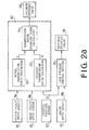
- An electronic control system for the clutch 3 and the belt-drive transmission 10 has an engine speed sensor 22, and rotating speed sensors 24 and 25 for respectively sensing rotating speeds of drive pulley 12 and the driven pulley 14.
- a selector lever connected to the selector mechanism 9 is provided with a select position sensor 20 for sensing the driving position (D), neutral position (N) and the reverse position (R).
- An accelerator pedal switch 21 is provided for sensing the depression of an accelerator pedal, and a throttle position sensor 29 is provided.
- a clutch plate position sensor 26 is further provided adjacent the DC motor 8 for sensing an actual position of the clutch plate 6.
- Output signals of the sensors and pulses of the switches are applied to an electronic control unit 27 which produces a control signal to the motor 8 and a control signal for controlling the transmission ratio (i) and a line pressure control signal to the control circuit.
- the transmission changing speed control section 30 further has a desired transmission ratio calculator 33 where a desired transmission ratio id is calculated in accordance with a desired drive pulley speed Npd, which is derived from a table, and the driven pulley speed N S .
- the desired transmission ratio id is fed to a transmission ratio changing speed calculator 34 which produces a desired transmission ratio changing speed di/dt.
- the speed di/dt is the amount of change of the desired transmission ratio id during a predetermined time interval.
- a duty ratio signal dependent on the desired transmission ratio changing speed di/dt is applied to a solenoid operated valve 35.
- the valve 35 is provided in the hydraulic circuits, for shifting a spool of the transmission ratio control valve TR to control the transmission ratio.
- a line pressure control section 31 is applied with an engine speed signal Ne from the sensor 22 and throttle opening degree ⁇ from the sensor 23 to obtain an engine torque T.
- a desired line pressure P LD is obtained in accordance with the engine torque T and the actual transmission ratio i.
- a duty ratio signal corresponding to the desired line pressure P LD is applied to a solenoid operated valve 36.
- the valve 36 is provided in the hydraulic circuit, for shifting a spool of the line pressure control valve LC to control the line pressure.
- the control unit comprises an actual clutch plate position detecting section 40 applied with a signal from the clutch plate position sensor 26 for obtaining an actual clutch plate position S, a clutch disengagement deciding section 41, a clutch partial engagement deciding section 42 and a clutch engagement deciding section 43.
- the driven pulley rotational speed N S is applied to the deciding sections 41 and 43 and signals from the select position sensor 20 and the accelerator pedal switch 21 are applied to the deciding sections 41 to 43.
- the deciding sections 41 to 43 are provided to decide a condition in which the clutch 3 is desired to be in accordance with an intention of the driver whether to start the vehicle or not.
- the disengagement of the clutch 3 is decided when a parking range (P-range) or a neutral range (N-range) is selected, or when the vehicle is driven while the accelerator pedal is released at the D-range or the R-range and when the driven pulley rotational speed N S becomes lower than a predetermined reference value N S1 .
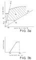
- the clutch disengagement range during the deceleration of the vehicle is designated by a solid wide line D1 in Fig. 3a showing a transmission operation pattern. Namely the line D1 is on an idle speed line N I , a largest transmission ratio line i L and on minimum transmission ratio changing line l L below the driven pulley speed N S1 .
- a clutch partial engagement zone D2 is a zone where the transmission ratio is larger than the largest transmission ratio line i L above the clutch disengagement line D1 as shown in Fig. 3a.
- an engagement zone D3 is shown in Fig. 3a between the smallest and largest transmission ratio lines i L and I OD′ above the minimum transmission ratio changing line l L.
- An output signal of the clutch disengagement deciding section 41 is applied to a desired clutch position deciding section 44 where a desired clutch plate position S D1 in the disengagement state of the clutch is set to a position at which the clutch plate 6 is slightly apart from the flywheel 4, determined in dependence on a characteristic of the clutch 3 shown in Fig. 3b.
- the desired clutch plate position S D1 and the actual clutch position S is applied to a comparator 45, an output signal of which is applied to a motor rotational direction setting section 46 and a motor rotational speed setting section 47.
- the rotational speed setting section 47 determines shifting speed of the release lever 7 and duty ratio D of the motor drive pulses dependent on the shifting speed.
- the duty ratio D is proportional to the speed of the clutch plate 6 as shown in Fig. 3c.
- a duty ratio signal corresponding to the duty ratio D and a direction signal is fed to a DC motor through a driver 48. Therefore when the release lever 7 is positioned so that the clutch plate 6 is not close enough to the flywheel 4 than the desired position S D1 (S ⁇ S D1 ), the motor rotational direction deciding section 46 produces a clutch engaging direction signal and the rotational speed deciding section 47 produces a predetermined duty ratio signal D S . Thus, the clutch plate 6 is shifted to the desired position S D1 close to the flywheel 4 at the speed dependent on the duty ratio D S . To the contrary, when the actual position of the clutch plate is closer to the flywheel 4 than the desired position (S >S D1 ), a disengaging direction signal and the duty ratio signal D S are produced. If the actual position coincides with the desired position, a zero duty ratio signal D0 is produced so that the motor is not driven.
- the partial engagement state is divided into three zones I, II and III as shown in Fig. 3d.
- a clutch plate position S D2 is a desired position.
- the clutch plate In the zone I, the clutch plate approaches the desired partial engagement position, and in the zone II, the clutch plate is held at the desired partial engagement position. In the zone III, the clutch plate approaches an entire engagement position S D3 .
- a desired clutch plate position deciding section 50 for partial engagement is supplied with the throttle opening degree ⁇ to set desired clutch plate position S D2 for the partial engagement state.
- the desired clutch plate position S D2 is set as an increasing function of the throttle opening degree ⁇ at the start of the vehicle as shown in Fig. 3e.
- the desired position S D2 and the actual position S are applied to first zone I deciding section 51, second zone II deciding section 52 and third zone III deciding section 53.
- the deciding section 53 is further fed with the desired transmission ratio id from the calculator 33. It is determined at the deciding section 51 that the clutch is in the first zone I when the actual clutch plate position S of the lever 7 is behind the desired position S D2 .
- the second zone II is determined at the deciding section 52 when the actual position S is at the desired position S D2
- a third zone III is determined at the deciding section 53 when the actual clutch plate position S exceeds the desired position S D2 .
- the first zone I is a zone where engagement rate of the clutch 3 is increased by shifting the clutch plate 6 from the position S D1 to S D2 at the highest speed, the second zone II where the clutch plate is kept at the position S D2 , the third zone III where the engagement rate of the clutch is further increased so as to lock up the clutch at the same time as the transmission ratio starts to change, that is when the desired transmission ratio id becomes smaller than the largest transmission ratio i L (id ⁇ i L ).
- Output signals of the deciding sections 51 to 53 are applied to the rotational direction setting section 46 where the rotational direction signal is produced, and the rotational speed setting section 47 where an appropriate duty ratio depending on the zones is produced.
- the setting section 47 produces the maximum duty ratio signal D M for the zone I, the zero duty ratio signal D O for the zone II and the predetermined duty ratio signal D S for the third zone III to actuate the DC motor 8.
- the desired clutch plate position S D3 is set at an entire engagement position at a desired clutch plate position deciding section 54 for the clutch lock-up state.
- the desired clutch plate position S D3 and actual position S are applied to a comparator 55.
- Output of the comparator 55 is applied to the motor rotational direction setting section 46 and the rotational speed setting section 47.
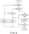
- the disengagement of the clutch 3 is decided at the clutch disengagement deciding section 41.
- the partial engagement state is decided at the partial engagement deciding section 42.
- the clutch is entirely engaged.
- the clutch is disengaged, thereby preventing the engine stall.
- the desired clutch plate position S D1 is set and the actual position S is compared with the desired position. While the vehicle is at a stop, when the actual position S is in a position where the clutch plate 6 and the flywheel 4 are far apart, the DC motor is rotated in the engaging direction at a duty ratio D S so as to reduce the clearance or play in the clutch 3. Thus, the clutch 3 is positioned so as to be able to start engaging at any moment.
- the DC motor 8 is rotated in the opposite direction at the duty ratio D S to position the clutch plate at the desired position.
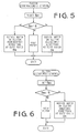
- the engagement state is controlled as shown by the flowchart of Fig. 6.
- the clutch plate position S is compared with desired position S D3 for the engagement of the clutch plate.
- the DC motor 8 is rotated in the engaging direction at the duty ratio D S .
- the duty ratio of drive pulses for motor becomes zero (D O ), and hence the motor 8 is not rotated, thereby keeping the clutch 3 locked up.
- the desired clutch position S D2 is obtained in dependence on the opening degree ⁇ at a step S101. If the disengagement of the clutch was determined at the last program (S102), the program proceeds to a step S103 where a flag 1 is set, thereby selecting the first zone I. The program goes to a step S105 where the actual clutch position S is compared with the desired position S D2 . When the actual position S is behind the desired position S D2 (S ⁇ S D2 ), the program proceeds to a step S114 passing through various steps, where it is confirmed that the flag 1 is set, and then to step S115. The motor 8 is rotated in the clutch engaging direction at he highest speed dependent on the maximum duty ratio D M . Thus, the clutch quickly becomes partial engagement state and the vehicle is started.
- the program goes to a step S106 where the flag 1 is reset and a flag 2 is set so as to select the second zone II.
- the program goes to a step S117.
- the motor 8 is applied with pulses at the zero duty ratio D0so as to keep the clutch position at S D2 .
- the flag 2 is reset and a flag 3 is set at step S109 so as to select the third zone III.
- the program proceeds to a step S111 where the desired position S D3 is set.
- the actual and desired clutch position S and S D3 are compared at a step S112.
- the program goes to a step S119, thereby applying motor drive pulses at the duty ratio D S to rotate the motor 8 in the clutch engaging direction at a step S119.
- the flag 3 is reset at a step S113.
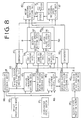
- Fig. 8 shows a modification of the present invention, where the control during the second zone II of the clutch partial engagement is carried out to prevent the engine speed from decreasing too rapidly when the clutch is engaged.
- a desired engine speed setting section 57 to which the throttle opening degree ⁇ is applied is provided.
- a desired engine speed Ned is determined in accordance with the throttle opening degree ⁇ as shown in a graph of Fig. 9. Namely, the desired engine speed Ned is set to be at a low value at a small throttle opening degree and to increase rapidly after exceeding a predetermined degree.
- the control unit is further provided with a clutch plate speed calculator 56 to which an output signal of the second zone II deciding section 52, actual engine speed Ne from the engine speed sensor 22 and the desired engine speed Ned from the desired engine speed setting section 57 are applied.
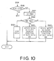
- the program proceeds to a step S121 where the desired engine speed Ned is determined in dependence on the throttle opening degree ⁇ .
- the desired engine speed Ned and the actual engine speed Ne are compared at a step S122.
- the program goes to a step S123, where the DC motor 8 is driven at the duty ratio Dd in the clutch disengagement direction to increase the engine speed.
- the program goes to a step S124 to drive the DC motor 8 at the duty ratio Dd in the clutch engaging direction, thereby decreasing the engine speed Ne.
- the clutch 3 is kept at the same position in accordance with the duty ratio D O at a step S125. Consequently, the clutch plate position S during the second zone II can be changed so as to gradually approach the flywheel 4.
- the engine speed is prevented from rapidly decreasing so as to improve the driveability. Since the desired engine speed is determined in accordance with the engine load, an appropriate clutch plate position dependent on the engine load is obtained.
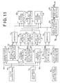
- a second modification of the present invention is provided with a learning control system for compensating dimensional variances of elements of the clutch which occur during manufacturing of the clutch, and deformation due to abrasion with elapse of time.
- the control unit has, in addition to sections of Fig. 2a and 2b, a clutch engagement starting position detecting section 58 to which the actual clutch plate position S and the drive pulley rotational speed N P from the sensor 24 are applied.
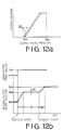
- a clutch position Sm of a clutch engagement starting point P (Fig. 13) at which the drive pulley 12 of the transmission 10 starts to rotate with the partial engagement of the clutch 3 is detected at the detecting section 58.
- the engagement starting point P shifts ahead and the release lever 7 is shifted.
- the abrasions and displacement of the engagement starting point P are detected.
- the clutch plate position Sm representing the point P is fed to a correcting quantity calculator 59 and stored in a memory.
- the clutch characteristic changes to a dotted line.
- the correcting quantity ⁇ S dependent on the change is calculated in the correcting quantity calculator 59 so as to correct the desired clutch position S D1 for the clutch disengagement state and the desired clutch position S D2 for the clutch partial engagement state as shown by a dotted line in Fig. 12b. Since the correcting operation is carried out each time the vehicle is started, the control of the clutch is accurately performed.
- a system for controlling a dry-plate friction clutch where a shock which occurs when the clutch is suddenly locked up is prevented.
- Actual clutch position is applied to the control system so as to carry out a feedback control, thereby accurately operating the clutch to engage and to lock-up.
- the position of the clutch plate is rapidly changed from the disengagement state to the partial engagement state so as to hasten the start of the vehicle.
- the desired clutch position can be varied in dependence on the throttle opening degree at the start of the vehicle so that starting characteristic is improved.
Landscapes
- Engineering & Computer Science (AREA)
- Mechanical Engineering (AREA)
- General Engineering & Computer Science (AREA)
- Chemical & Material Sciences (AREA)
- Combustion & Propulsion (AREA)
- Transportation (AREA)
- Automation & Control Theory (AREA)
- Physics & Mathematics (AREA)
- Fluid Mechanics (AREA)
- Hydraulic Clutches, Magnetic Clutches, Fluid Clutches, And Fluid Joints (AREA)
- Control Of Driving Devices And Active Controlling Of Vehicle (AREA)
Applications Claiming Priority (6)
| Application Number | Priority Date | Filing Date | Title |
|---|---|---|---|
| JP18973/88 | 1988-01-29 | ||
| JP63018972A JPH01195147A (ja) | 1988-01-29 | 1988-01-29 | 無段変速機付車両のクラッチ制御装置 |
| JP18972/88 | 1988-01-29 | ||
| JP1897388A JPH01195142A (ja) | 1988-01-29 | 1988-01-29 | 無段変速機付車両のクラッチ制御装置 |
| JP63018974A JPH01193416A (ja) | 1988-01-29 | 1988-01-29 | 車両用乾式クラッチの制御装置 |
| JP18974/88 | 1988-01-29 |
Publications (2)
| Publication Number | Publication Date |
|---|---|
| EP0326274A2 true EP0326274A2 (de) | 1989-08-02 |
| EP0326274A3 EP0326274A3 (de) | 1991-02-06 |
Family
ID=27282442
Family Applications (1)
| Application Number | Title | Priority Date | Filing Date |
|---|---|---|---|
| EP19890300427 Withdrawn EP0326274A3 (de) | 1988-01-29 | 1989-01-18 | Kupplungssteuerung für ein Kraftfahrzeug |
Country Status (2)
| Country | Link |
|---|---|
| US (1) | US4986396A (de) |
| EP (1) | EP0326274A3 (de) |
Cited By (6)
| Publication number | Priority date | Publication date | Assignee | Title |
|---|---|---|---|---|
| EP0497038A1 (de) * | 1991-01-30 | 1992-08-05 | Borg-Warner Automotive, Inc. | Steuerungsstrategien für ein stufenlos verstellbares Getriebe mit zwei Geschwindigkeitsbereichen |
| WO1993000228A1 (de) * | 1991-06-21 | 1993-01-07 | Dr.Ing. H.C. F. Porsche Aktiengesellschaft | Verfahren zur selbsttätigen steuerung einer drehzahlwandelnden anfahreinrichtung eines kraftfahrzeugs |
| WO1993000227A1 (en) * | 1991-06-28 | 1993-01-07 | Automotive Products Plc | A clutch control system |
| US5417621A (en) * | 1993-12-22 | 1995-05-23 | Ford Motor Company | Driveaway lockup strategy for an infinitely variable tranmission with a hydrokinetic torque converter |
| EP1547850A3 (de) * | 2003-12-22 | 2009-07-01 | Hitachi Ltd. | Automatisches Getriebe, Steuervorrichtung und Steuersystem |
| EP2607670A4 (de) * | 2010-08-20 | 2018-03-28 | Toyota Jidosha Kabushiki Kaisha | Steuervorrichtung für einen fahrzeugmotor |
Families Citing this family (8)
| Publication number | Priority date | Publication date | Assignee | Title |
|---|---|---|---|---|
| US5544469A (en) * | 1988-09-26 | 1996-08-13 | Southpac Trust International, Inc. | Wrapping material having an extension for design indicia for wrapping flower pots and floral arrangements and methods |
| JP3084929B2 (ja) * | 1992-06-01 | 2000-09-04 | 株式会社デンソー | スロットル基準開度検出装置 |
| JP3237419B2 (ja) | 1994-10-21 | 2001-12-10 | トヨタ自動車株式会社 | 車両用クラッチ制御装置 |
| US6071211A (en) * | 1998-11-18 | 2000-06-06 | Eaton Corporation | Idle drive torque control for automated vehicle master clutch |
| JP5573747B2 (ja) | 2011-03-23 | 2014-08-20 | アイシン精機株式会社 | ハイブリッド車両の変速制御装置 |
| EP2689980B1 (de) | 2011-03-25 | 2019-04-24 | Aisin Seiki Kabushiki Kaisha | Getriebesteuerungsvorrichtung für ein hybridfahrzeug |
| CN105452719B (zh) * | 2013-08-09 | 2018-02-13 | 本田技研工业株式会社 | 动力传递切换机构和变速器 |
| US10024427B1 (en) * | 2017-01-19 | 2018-07-17 | GM Global Technology Operations LLC | System and method for ratio control in a vehicle continuously variable transmission |
Family Cites Families (21)
| Publication number | Priority date | Publication date | Assignee | Title |
|---|---|---|---|---|
| GB1514371A (en) * | 1976-03-03 | 1978-06-14 | Nissan Motor | Clutch actuating apparatus |
| US4081065A (en) * | 1976-12-23 | 1978-03-28 | Smyth Robert Ralston | Controlled power clutch |
| DE2927175A1 (de) * | 1978-08-03 | 1981-02-19 | Volkswagenwerk Ag | Einrichtung zur automatischen betaetigung einer kraftfahrzeugkupplung |
| DE2833961A1 (de) * | 1978-08-03 | 1980-02-21 | Volkswagenwerk Ag | Einrichtung zur automatischen betaetigung einer kraftfahrzeugkupplung |
| JPS56128229A (en) * | 1980-02-18 | 1981-10-07 | Automotive Prod Co Ltd | Controller for transmission clutch of automobile |
| US4515041A (en) * | 1980-05-21 | 1985-05-07 | Aisin Seiki Kabushiki Kaisha | Control system and method for a power delivery system having a continuously variable ratio transmission |
| DE3032558C2 (de) * | 1980-08-29 | 1987-01-02 | Zahnradfabrik Friedrichshafen Ag, 7990 Friedrichshafen | Logistische Meßeinrichtung für Kupplungen oder Bremsen |
| US4433594A (en) * | 1981-04-24 | 1984-02-28 | Borg-Warner Corporation | Variable pulley transmission |
| AU1725283A (en) * | 1982-08-11 | 1984-02-16 | Automotive Products Plc | Clutch control system |
| JPS6034525A (ja) * | 1983-08-05 | 1985-02-22 | Fujitsu Ltd | クラツチ制御装置 |
| JPS6078119A (ja) * | 1983-10-03 | 1985-05-02 | Ono Sokki Co Ltd | クラツチ制御方法 |
| US4665773A (en) * | 1984-03-13 | 1987-05-19 | Mitsubishi Jidosha Kogyo Kabushiki Kaisha | Continuously variable transmission apparatus for automobile |
| JPS60176925U (ja) * | 1984-05-07 | 1985-11-25 | 日産自動車株式会社 | 自動クラツチの制御装置 |
| GB2158912A (en) * | 1984-05-14 | 1985-11-20 | Nissan Motor | Automatic clutch control system |
| JPH0711294B2 (ja) * | 1984-07-16 | 1995-02-08 | 本田技研工業株式会社 | 発進クラツチ |
| US4646891A (en) * | 1985-01-31 | 1987-03-03 | Eaton Corporation | Automatic clutch control |
| JPS61196831A (ja) * | 1985-02-26 | 1986-09-01 | Diesel Kiki Co Ltd | 内燃機関車輛用自動発進制御装置 |
| JPS61197824A (ja) * | 1985-02-28 | 1986-09-02 | Isuzu Motors Ltd | クラツチ制御装置 |
| US4648496A (en) * | 1985-04-12 | 1987-03-10 | Borg-Warner Automotive, Inc. | Clutch control system for a continuously variable transmission |
| US4700590A (en) * | 1985-09-30 | 1987-10-20 | Aisin Seiki Kabushiki Kaisha | System for utilizing the negative torque of a power delivery system having a continuously variable ratio transmission for braking |
| JPH061089B2 (ja) * | 1986-09-13 | 1994-01-05 | ダイハツ工業株式会社 | 自動変速機の発進クラツチ制御方法 |
-
1989
- 1989-01-18 EP EP19890300427 patent/EP0326274A3/de not_active Withdrawn
- 1989-01-18 US US07/300,443 patent/US4986396A/en not_active Expired - Fee Related
Cited By (9)
| Publication number | Priority date | Publication date | Assignee | Title |
|---|---|---|---|---|
| EP0497038A1 (de) * | 1991-01-30 | 1992-08-05 | Borg-Warner Automotive, Inc. | Steuerungsstrategien für ein stufenlos verstellbares Getriebe mit zwei Geschwindigkeitsbereichen |
| WO1993000228A1 (de) * | 1991-06-21 | 1993-01-07 | Dr.Ing. H.C. F. Porsche Aktiengesellschaft | Verfahren zur selbsttätigen steuerung einer drehzahlwandelnden anfahreinrichtung eines kraftfahrzeugs |
| US5433677A (en) * | 1991-06-21 | 1995-07-18 | Dr. Ing. H.C.F. Porsche Ag | Method for automatic control of an RPM-changing engaging device of a motor vehicle |
| WO1993000227A1 (en) * | 1991-06-28 | 1993-01-07 | Automotive Products Plc | A clutch control system |
| GB2273141A (en) * | 1991-06-28 | 1994-06-08 | Automotive Products Plc | A clutch control system |
| GB2273141B (en) * | 1991-06-28 | 1995-04-05 | Automotive Products Plc | A clutch control system |
| US5417621A (en) * | 1993-12-22 | 1995-05-23 | Ford Motor Company | Driveaway lockup strategy for an infinitely variable tranmission with a hydrokinetic torque converter |
| EP1547850A3 (de) * | 2003-12-22 | 2009-07-01 | Hitachi Ltd. | Automatisches Getriebe, Steuervorrichtung und Steuersystem |
| EP2607670A4 (de) * | 2010-08-20 | 2018-03-28 | Toyota Jidosha Kabushiki Kaisha | Steuervorrichtung für einen fahrzeugmotor |
Also Published As
| Publication number | Publication date |
|---|---|
| EP0326274A3 (de) | 1991-02-06 |
| US4986396A (en) | 1991-01-22 |
Similar Documents
| Publication | Publication Date | Title |
|---|---|---|
| US5029678A (en) | Automatic clutch control apparatus | |
| US5056637A (en) | System for controlling speed of an engine for a motor vehicle having a continuously variable transmission | |
| EP0231059B1 (de) | Steuervorrichtung für ein stufenlos regelbares Getriebe | |
| EP0242127B1 (de) | Steuersystem für eine Fahrzeugkupplung | |
| EP0240283B1 (de) | Steuersystem für eine Kraftfahrzeugkupplung | |
| US4986396A (en) | Control system for a clutch of a motor vehicle | |
| GB2263519A (en) | System for controlling a continuously-variable transmission for a motor vehicle | |
| US5362287A (en) | Control system for an automatic clutch of a motor vehicle | |
| US5009127A (en) | Transmission ratio control system for a continuously variable transmission | |
| EP0364270A1 (de) | Übersetzungssteuerung für ein kontinuierlich variables Getriebe | |
| US4947971A (en) | Control system for a clutch for a motor vehicle | |
| US4880094A (en) | Control system for a clutch for a vehicle | |
| US5069319A (en) | Control system for a clutch of a motor vehicle | |
| US4923433A (en) | Transmission ratio control system for a continuously variable transmission | |
| US5209332A (en) | Control system for a clutch of a motor vehicle | |
| EP0161085B1 (de) | Steuersystem für ein stufenloses Getriebe | |
| EP0297819A2 (de) | Getriebeübersetzungs-Steuerungssystem für ein stufenloses Getriebe | |
| US4825991A (en) | Control system for a clutch for a vehicle | |
| EP0251571B1 (de) | Fahrzeugkupplungssteuersystem | |
| US4977988A (en) | Control system for a clutch for a vehicle | |
| US6135916A (en) | Process for controlling the pressure of a CVT during a standing start | |
| EP0240284B1 (de) | Steuersystem für eine elektromagnetische Fahrzeugkupplung | |
| JP3453986B2 (ja) | 無段自動変速機の変速制御装置 | |
| EP0243195B1 (de) | Fahrzeugkupplungssteuersystem | |
| EP0240281B1 (de) | Steuersystem für eine elektromagnetische Kraftfahrzeugkupplung |
Legal Events
| Date | Code | Title | Description |
|---|---|---|---|
| PUAI | Public reference made under article 153(3) epc to a published international application that has entered the european phase |
Free format text: ORIGINAL CODE: 0009012 |
|
| 17P | Request for examination filed |
Effective date: 19890130 |
|
| AK | Designated contracting states |
Kind code of ref document: A2 Designated state(s): DE GB IT NL |
|
| PUAL | Search report despatched |
Free format text: ORIGINAL CODE: 0009013 |
|
| AK | Designated contracting states |
Kind code of ref document: A3 Designated state(s): DE GB IT NL |
|
| 17Q | First examination report despatched |
Effective date: 19920804 |
|
| STAA | Information on the status of an ep patent application or granted ep patent |
Free format text: STATUS: THE APPLICATION IS DEEMED TO BE WITHDRAWN |
|
| 18D | Application deemed to be withdrawn |
Effective date: 19921215 |