EP0326275A2 - Système calculateur pouvant fonctionner avec plusieurs modes d'affichage - Google Patents
Système calculateur pouvant fonctionner avec plusieurs modes d'affichage Download PDFInfo
- Publication number
- EP0326275A2 EP0326275A2 EP89300429A EP89300429A EP0326275A2 EP 0326275 A2 EP0326275 A2 EP 0326275A2 EP 89300429 A EP89300429 A EP 89300429A EP 89300429 A EP89300429 A EP 89300429A EP 0326275 A2 EP0326275 A2 EP 0326275A2
- Authority
- EP
- European Patent Office
- Prior art keywords
- display controller
- built
- optional
- computer system
- control means
- Prior art date
- Legal status (The legal status is an assumption and is not a legal conclusion. Google has not performed a legal analysis and makes no representation as to the accuracy of the status listed.)
- Withdrawn
Links
Images
Classifications
-
- G—PHYSICS
- G06—COMPUTING OR CALCULATING; COUNTING
- G06F—ELECTRIC DIGITAL DATA PROCESSING
- G06F3/00—Input arrangements for transferring data to be processed into a form capable of being handled by the computer; Output arrangements for transferring data from processing unit to output unit, e.g. interface arrangements
- G06F3/14—Digital output to display device ; Cooperation and interconnection of the display device with other functional units
-
- G—PHYSICS
- G06—COMPUTING OR CALCULATING; COUNTING
- G06F—ELECTRIC DIGITAL DATA PROCESSING
- G06F3/00—Input arrangements for transferring data to be processed into a form capable of being handled by the computer; Output arrangements for transferring data from processing unit to output unit, e.g. interface arrangements
- G06F3/14—Digital output to display device ; Cooperation and interconnection of the display device with other functional units
- G06F3/153—Digital output to display device ; Cooperation and interconnection of the display device with other functional units using cathode-ray tubes
-
- G—PHYSICS
- G09—EDUCATION; CRYPTOGRAPHY; DISPLAY; ADVERTISING; SEALS
- G09G—ARRANGEMENTS OR CIRCUITS FOR CONTROL OF INDICATING DEVICES USING STATIC MEANS TO PRESENT VARIABLE INFORMATION
- G09G2360/00—Aspects of the architecture of display systems
- G09G2360/02—Graphics controller able to handle multiple formats, e.g. input or output formats
-
- G—PHYSICS
- G09—EDUCATION; CRYPTOGRAPHY; DISPLAY; ADVERTISING; SEALS
- G09G—ARRANGEMENTS OR CIRCUITS FOR CONTROL OF INDICATING DEVICES USING STATIC MEANS TO PRESENT VARIABLE INFORMATION
- G09G2360/00—Aspects of the architecture of display systems
- G09G2360/04—Display device controller operating with a plurality of display units
Definitions
- the present invention relate to a computer system to which display controllers of a plurality of types, such as those which may use a CGA (colour graphics adapter) mode, an EGA (enhanced graphics adapter) mode, and a VGA (video graphics array) mode, are connectable.
- CGA colour graphics adapter
- EGA enhanced graphics adapter
- VGA video graphics array
- Display controllers using CGA, EGA, and VGA have the characteristics identified in Table 1 below. TABLE 1 Mode Resolution Color Specification CGA 640*200 dots 4 colors EGA 640*350 dots 16 colors can be displayed simultaneously out of 64 colors VGA 640*480 dots 256 colors can be displayed simultaneously out of 260,000 colors
- the display controllers have operated by use of both chips achieving the above specifications and also basic input/output system (BIOS) programs supporting them.
- BIOS basic input/output system
- the display controller which the user wants to use is selected from among available display controllers by operating a switch. Alternatively, it is designated through an input device (e.g.,a keyboard) by executing a setup program or the like after the system is turned on. If the display controller to be used is of a different type from that of the display controlled used last, the user has to determine all the display setup conditions or designate a setup program to be executed.
- Some of the conventional computer systems permit an optional display controller to be connected thereto, in addition to a built-up display controller, in such a manner that the optional display adapter is located either inside or outside of the main body of the computer systems. Even if the optional display controller is connected, however, it is usual that the built-up display controller is automatically selected prior to the optional display controller. Therefore, the user is not allowed to freely select the display controller which he or she wants to use.
- the present invention has been developed in consideration of the above circumstances, and is intended to provide a computer system which permits the user to freely select either a built-in display controller or an optionally provided display controller, automatically performs a setup operation in accordance with the operating condition of the system, and is actuated with a display controller desired by the user.
- the computer system of the present invention comprises: a built-in display controller including a ROM for storing a BIOS including an identification (ID) of the type of display controller which is built-in; an optional display controller adapted to be connected to the computer system; a memory for storing setup information regarding the system; and a ROM for storing a system BIOS, which includes means for: 1) reading the ID of the built-in display controller when the system is turned on, and actuating system, with the built-in display controller selected in accordance with operating conditions of the system and the user selection, and 2) discriminating the type of the optional display controller, executing a setup program in accordance with the discriminated type, and actuating the system, with the display controller selected in accordance with the user selection.
- a built-in display controller including a ROM for storing a BIOS including an identification (ID) of the type of display controller which is built-in
- an optional display controller adapted to be connected to the computer system
- a memory for storing setup information regarding the system
- the built-in display controller, the optional display controller, the memory, and the ROM (system BIOS) are connected to a CPU through a system bus.
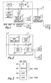
- FIGURE 1 illustrates the construction of a computer system according to one embodiment of the present invention.
- CPU 1, ROM 2, manual switch 4, RAM 6, and optional display controller 5 are connected to system bus 11.
- Built-in display controller 3, having a conventional, well-known, structure, is connected to system bus 11 through manual switch 4.
- CPU 1 constitutes the essential part of the controller of the system.
- ROM 2 stores a system BIOS program with which to control inputs and outputs of the system.
- BIOS is an abbreviation of "Basic Input Output System” and indicates input/ output control programs for enabling operation of input and output devices connected to a system.
- Most of the input/output control programs (including a CGA BIOS) are stored in ROM 2 as a part of system BIOS.
- the input/output programs of built-in display controller 3, when expanded to function in an EGA mode, a VGA mode, etc., are stored in ROM 31 (See FIGURE 2) of display controller 3 as an optional BIOS.
- Switch 4 is a manual switch to be operated by the user. When this switch is on, the ID in the EGA BIOS stored in ROM 31 of built-in display adapter 3 can be read. When the switch is off, the ID cannot be read.
- ROM 31 which stores an EGA BIOS
- video RAM 32 which stores display data
- EGA chip 33 which generates display signals suitable to plasma display (PDP) 9 and CRT 10
- EGA gate array 34 which controls the display functions of plasma display 9 and CRT 10 are connected to bus 35 of built-in display controller 3.
- EGA BIOS program data is displayed on either PDP 9 or CRT 10 under the control of CPU 1.
- the EGA BIOS includes: ID data 311 provided only for an EGA display controller; control program 312 for the EGA; FONT data 313 for the EGA; and FONT data 314 for a CGA.
- Display controller "EGA” covers the "CGA” function as well.
- the CGA is controlled on the basis of system BIOS stored in ROM 2.
- controller 3 is capable of the EGA mode, but is not limited thereto.
- controller 3 can be made to operate in a VGA mode by incorporating a VGA chip, VGA gate array and a VGA BIOS.
- Optional display controller 5 may be located either inside or outside of the main body of the system.
- the internal structure of optional display controller 5 is similar to that of built-in display controller 3.
- the user can freely determine the type of display controller from among the CGA mode, EGA mode, VGA mode, etc.
- CRT 10 is connected to optional display 5.
- the setup information for the system is written in RAM 6. Battery 8 for backup use is connected to RAM 6.
- Either built-in display controller 3 (hereafter "DC") or optional DC 5 is selected beforehand by the user by means of switch 4.
- the computer system determines whether or not the ID in built-in DC 3 is readable.
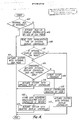
- CPU 1 receives a system actuation command and executes the following operation, on the basis of the system BIOS.
- the ID written in the BIOS of built-in DC 3 is read at step 402, so as to determine which DC, built-in DC 3 or optional DC 5, has been selected by the user. This ID is included in the EGA BIOS only. If the ID can be read, built-in DC 3 is regarded as having been selected. Accordingly, the system is actuated with built-in DC 3 at step 404.
- optional DC 5 is regarded as having been selected.
- built-in DC 3 is temporarily actuated at step 406, using the CGA mode. Since, therefore, the display device of the computer system can be used, an error message or the like can be displayed.
- the CGA mode is actuated by use of the system BIOS.
- step 408 it is checked whether or not optional DC 5 is a CGA mode at step 408. If it is found at step 410 that the optional DC 5 is a CGA mode, the system is actuated at step 412 with optional DC 5.
- optional DC 5 is not a CGA
- information representing the type of optional DC 5 is read, on the basis of the memory capacity of the video RAM of optional DC 5. That is, the address space in which a video RAM in optional DC 5 is located is determined. For example, if the address space extends from B8000 H to BFFFF H (16K bytes), this is appropriate for CGA and if the address space extends from A0000 H to BFFFF H (32K bytes), this is appropriate for EGA. Since, in this way, the capacity of the video RAM differs upon the type of display controller, it can be used for discriminating the type of the display controller.
- the information thus read is compared with the setup information stored in system RAM 6 at step 414.
- the DC to be used is considered to be of the same type as the DC used last. In this case, the display of the system is actuated, using the same optional DC used last at step 416. If coincidence is not detected in the comparison at step 414, the DC to be used is considered to have been replaced with another or removed from the system. Since, in this case, a setup operation must be performed, execution of the setup program is commanded at step 418. There, the user selects at step 420 the type of the DC from among the EGA mode, VGA mode, etc., using the information indicated on the screen. In response to the section, information regarding the DC newly selected by the user is written in RAM 6 at step 422, and the display of the system is actuated at step 424, with the newly selected DC.
Landscapes
- Engineering & Computer Science (AREA)
- Theoretical Computer Science (AREA)
- Human Computer Interaction (AREA)
- Physics & Mathematics (AREA)
- General Engineering & Computer Science (AREA)
- General Physics & Mathematics (AREA)
- Controls And Circuits For Display Device (AREA)
- Stored Programmes (AREA)
- Control Of Indicators Other Than Cathode Ray Tubes (AREA)
- Digital Computer Display Output (AREA)
- Input From Keyboards Or The Like (AREA)
Applications Claiming Priority (2)
| Application Number | Priority Date | Filing Date | Title |
|---|---|---|---|
| JP63014634A JPH01191914A (ja) | 1988-01-27 | 1988-01-27 | コンピュータシステム |
| JP14634/88 | 1988-01-27 |
Publications (2)
| Publication Number | Publication Date |
|---|---|
| EP0326275A2 true EP0326275A2 (fr) | 1989-08-02 |
| EP0326275A3 EP0326275A3 (fr) | 1992-02-26 |
Family
ID=11866629
Family Applications (1)
| Application Number | Title | Priority Date | Filing Date |
|---|---|---|---|
| EP19890300429 Withdrawn EP0326275A3 (fr) | 1988-01-27 | 1989-01-18 | Système calculateur pouvant fonctionner avec plusieurs modes d'affichage |
Country Status (4)
| Country | Link |
|---|---|
| US (1) | US5072411A (fr) |
| EP (1) | EP0326275A3 (fr) |
| JP (1) | JPH01191914A (fr) |
| KR (1) | KR920009162B1 (fr) |
Cited By (11)
| Publication number | Priority date | Publication date | Assignee | Title |
|---|---|---|---|---|
| EP0419904A3 (en) * | 1989-09-29 | 1992-03-11 | Kabushiki Kaisha Toshiba | Method and system for controlling cpu wait time in computer capable of connecting externally provided input/output controller |
| EP0419910A3 (en) * | 1989-09-29 | 1992-05-27 | Kabushiki Kaisha Toshiba | Display control system |
| EP0456410A3 (en) * | 1990-05-10 | 1993-06-02 | International Business Machines Corporation | Adapter card |
| US5351064A (en) * | 1987-06-19 | 1994-09-27 | Kabushiki Kaisha Toshiba | CRT/flat panel display control system |
| US5430457A (en) * | 1987-06-19 | 1995-07-04 | Kabushiki Kaisha Toshiba | CRT/flat panel display control system |
| US5475402A (en) * | 1992-06-04 | 1995-12-12 | Kabushiki Kaisha Toshiba | Display control apparatus and method |
| US5508714A (en) * | 1988-09-13 | 1996-04-16 | Kabushiki Kaisha Toshiba | Display control apparatus for converting CRT resolution into PDP resolution by hardware |
| WO2001097006A1 (fr) * | 2000-06-14 | 2001-12-20 | Intel Corporation | Concentrateur de controleur de memoire |
| DE4025295C2 (de) * | 1989-08-10 | 2003-06-18 | Apple Computer | Computer zur Wiedergabe von Videodaten auf einem Monitor |
| US6859208B1 (en) | 2000-09-29 | 2005-02-22 | Intel Corporation | Shared translation address caching |
| US7116331B1 (en) | 2000-08-23 | 2006-10-03 | Intel Corporation | Memory controller hub interface |
Families Citing this family (26)
| Publication number | Priority date | Publication date | Assignee | Title |
|---|---|---|---|---|
| JPH0218594A (ja) * | 1988-07-07 | 1990-01-22 | Canon Inc | 表示制御装置 |
| JPH03154341A (ja) * | 1989-11-10 | 1991-07-02 | Toshiba Corp | 半導体装置 |
| JPH03160494A (ja) * | 1989-11-10 | 1991-07-10 | Internatl Business Mach Corp <Ibm> | データ処理装置 |
| JPH0455890A (ja) * | 1990-06-25 | 1992-02-24 | Canon Inc | 画像データ制御装置及び表示システム |
| EP0520454B1 (fr) * | 1991-06-26 | 1998-10-14 | Kabushiki Kaisha Toshiba | Système de commande d'affichage pour déterminer la connexion d'un dispositif d'affichage optionnel en utilisant une palette |
| JPH0573016A (ja) * | 1991-09-17 | 1993-03-26 | Toshiba Corp | 表示制御装置 |
| US5379052A (en) * | 1992-03-26 | 1995-01-03 | Unisys Corporation | VGA and EGA video controller apparatus using shared common video memory |
| US5603011A (en) * | 1992-12-11 | 1997-02-11 | International Business Machines Corporation | Selective shadowing and paging in computer memory systems |
| US5581788A (en) * | 1992-12-14 | 1996-12-03 | At&T Global Information Solutions Company | System for testing the functionality of video cord and monitor by using program to enable user to view list of modes and select compatible mode |
| JP3334211B2 (ja) * | 1993-02-10 | 2002-10-15 | 株式会社日立製作所 | ディスプレイ |
| US5418962A (en) * | 1993-03-31 | 1995-05-23 | International Business Machines Corporation | Video display adapter control system |
| US5751270A (en) * | 1993-08-06 | 1998-05-12 | Intel Corporation | Method and apparatus for displaying an image using direct memory access |
| US5572232A (en) * | 1993-08-06 | 1996-11-05 | Intel Corporation | Method and apparatus for displaying an image using subsystem interrogation |
| US5546103A (en) * | 1993-08-06 | 1996-08-13 | Intel Corporation | Method and apparatus for displaying an image in a windowed environment |
| US5652601A (en) * | 1993-08-06 | 1997-07-29 | Intel Corporation | Method and apparatus for displaying a color converted image |
| EP0663659A3 (fr) * | 1993-12-30 | 1995-11-22 | Ibm | Affichage de caractères dans un système de traitement de données. |
| US5495263A (en) * | 1994-01-28 | 1996-02-27 | Compaq Computer Corp. | Identification of liquid crystal display panels |
| JPH07271629A (ja) * | 1994-03-29 | 1995-10-20 | Mitsubishi Electric Corp | マイクロコンピュータ |
| US5799204A (en) * | 1995-05-01 | 1998-08-25 | Intergraph Corporation | System utilizing BIOS-compatible high performance video controller being default controller at boot-up and capable of switching to another graphics controller after boot-up |
| US5977933A (en) * | 1996-01-11 | 1999-11-02 | S3, Incorporated | Dual image computer display controller |
| US5938772A (en) * | 1997-06-11 | 1999-08-17 | Compaq Computer Corporation | Responsive backlit hardwire button array providing illumination and user feedback in a computer |
| US6094690A (en) * | 1997-11-13 | 2000-07-25 | Samsung Electronics Co., Ltd. | Computer system with dynamic enabling and disabling function of the internal VGA module |
| US6304244B1 (en) * | 1998-04-24 | 2001-10-16 | International Business Machines Corporation | Method and system for dynamically selecting video controllers present within a computer system |
| US6624816B1 (en) | 1999-09-10 | 2003-09-23 | Intel Corporation | Method and apparatus for scalable image processing |
| US7042459B2 (en) * | 2001-01-23 | 2006-05-09 | Dell Products L.P. | System for providing a video signal to a display device in a scalable platform |
| US7072274B2 (en) * | 2002-05-31 | 2006-07-04 | Lenovo (Singapore) Pte, Ltd. | Adaptive mounting system for data storage devices |
Family Cites Families (4)
| Publication number | Priority date | Publication date | Assignee | Title |
|---|---|---|---|---|
| JPS58205214A (ja) * | 1982-05-26 | 1983-11-30 | Omron Tateisi Electronics Co | プログラマブル・コントロ−ラのモニタ表示方式 |
| US4639721A (en) * | 1982-10-09 | 1987-01-27 | Sharp Kabushiki Kaisha | Data selection circuit for the screen display of data from a personal computer |
| US4646077A (en) * | 1984-01-16 | 1987-02-24 | Texas Instruments Incorporated | Video display controller system with attribute latch |
| DE3852148T2 (de) * | 1987-06-19 | 1995-04-06 | Toshiba Kawasaki Kk | Anzeigemodusumschaltsystem für ein Plasmaanzeigegerät. |
-
1988
- 1988-01-27 JP JP63014634A patent/JPH01191914A/ja active Pending
-
1989
- 1989-01-18 EP EP19890300429 patent/EP0326275A3/fr not_active Withdrawn
- 1989-01-27 KR KR1019890000853A patent/KR920009162B1/ko not_active Expired
- 1989-01-27 US US07/302,263 patent/US5072411A/en not_active Expired - Fee Related
Cited By (16)
| Publication number | Priority date | Publication date | Assignee | Title |
|---|---|---|---|---|
| US5430457A (en) * | 1987-06-19 | 1995-07-04 | Kabushiki Kaisha Toshiba | CRT/flat panel display control system |
| US5351064A (en) * | 1987-06-19 | 1994-09-27 | Kabushiki Kaisha Toshiba | CRT/flat panel display control system |
| US5508714A (en) * | 1988-09-13 | 1996-04-16 | Kabushiki Kaisha Toshiba | Display control apparatus for converting CRT resolution into PDP resolution by hardware |
| DE4025295C2 (de) * | 1989-08-10 | 2003-06-18 | Apple Computer | Computer zur Wiedergabe von Videodaten auf einem Monitor |
| EP0803796A3 (fr) * | 1989-09-29 | 1997-11-12 | Kabushiki Kaisha Toshiba | Système de commande d'affichage avec verrouillage du signal d'attaque pour un affichage CRT optionnel non activé |
| US5629715A (en) * | 1989-09-29 | 1997-05-13 | Kabushiki Kaisha Toshiba | Display control system |
| EP0419904A3 (en) * | 1989-09-29 | 1992-03-11 | Kabushiki Kaisha Toshiba | Method and system for controlling cpu wait time in computer capable of connecting externally provided input/output controller |
| EP0419910A3 (en) * | 1989-09-29 | 1992-05-27 | Kabushiki Kaisha Toshiba | Display control system |
| EP0456410A3 (en) * | 1990-05-10 | 1993-06-02 | International Business Machines Corporation | Adapter card |
| US5475402A (en) * | 1992-06-04 | 1995-12-12 | Kabushiki Kaisha Toshiba | Display control apparatus and method |
| WO2001097006A1 (fr) * | 2000-06-14 | 2001-12-20 | Intel Corporation | Concentrateur de controleur de memoire |
| US6734862B1 (en) | 2000-06-14 | 2004-05-11 | Intel Corporation | Memory controller hub |
| US7116331B1 (en) | 2000-08-23 | 2006-10-03 | Intel Corporation | Memory controller hub interface |
| US7327370B2 (en) | 2000-08-23 | 2008-02-05 | Intel Corporation | Memory controller hub interface |
| US6859208B1 (en) | 2000-09-29 | 2005-02-22 | Intel Corporation | Shared translation address caching |
| US7145568B2 (en) | 2000-09-29 | 2006-12-05 | Intel Corporation | Shared translation address caching |
Also Published As
| Publication number | Publication date |
|---|---|
| KR890012218A (ko) | 1989-08-25 |
| JPH01191914A (ja) | 1989-08-02 |
| EP0326275A3 (fr) | 1992-02-26 |
| US5072411A (en) | 1991-12-10 |
| KR920009162B1 (ko) | 1992-10-14 |
Similar Documents
| Publication | Publication Date | Title |
|---|---|---|
| US5072411A (en) | Computer system which can operate in a plurality of display modes | |
| EP0786736B2 (fr) | Imprimante et méthode de contrôle associée | |
| US4990904A (en) | Display mode switching system for flat panel display apparatus | |
| US5568397A (en) | Logic circuit diagram editor system | |
| EP0416257A2 (fr) | Ordinateur personnel permettant d'utiliser sélectivement un clavier intégré ou un clavier externe, au moyen d'un sélecteur | |
| US4804948A (en) | Video display control system | |
| EP0556059B1 (fr) | Procédé et appareil de sortie | |
| US4734857A (en) | Fixed amount or fixed rate discount/premium calculation in an electronic cash register | |
| US5495560A (en) | Output apparatus which temporarily stores pattern data for output | |
| US5347265A (en) | Information processing apparatus providing a connection state | |
| US5522062A (en) | Personal computer for accessing two types of extended memories having different memory capacities | |
| US5377358A (en) | Character processing device adapted to perform document-editing processing and typewriting processing | |
| US5745107A (en) | Window display control system for computers and method therefor | |
| EP0827080A2 (fr) | Micro-ordinateur avec unité d'autodiagnostic | |
| US5577257A (en) | Information processing apparatus | |
| US5239485A (en) | System and method for determining the revision history of printed circuit boards | |
| US5427459A (en) | Printer with command inhibitor | |
| US5566286A (en) | Method and apparatus for verifying dimensional values of a drawing | |
| JP3045400U (ja) | 電子機器の仕向地別初期設定装置 | |
| JPS6113234B2 (fr) | ||
| JP2002259132A (ja) | 情報処理装置 | |
| JPH05181648A (ja) | アプリケーションソフトウエア動作環境最適化方法 | |
| JP2899438B2 (ja) | ジャンパ・リフト装置 | |
| JPH06103238A (ja) | 情報処理装置 | |
| KR100217376B1 (ko) | 금전등록기의 프로그램영역 크기 확장제어방법 |
Legal Events
| Date | Code | Title | Description |
|---|---|---|---|
| PUAI | Public reference made under article 153(3) epc to a published international application that has entered the european phase |
Free format text: ORIGINAL CODE: 0009012 |
|
| 17P | Request for examination filed |
Effective date: 19890130 |
|
| AK | Designated contracting states |
Kind code of ref document: A2 Designated state(s): DE FR GB |
|
| PUAL | Search report despatched |
Free format text: ORIGINAL CODE: 0009013 |
|
| AK | Designated contracting states |
Kind code of ref document: A3 Designated state(s): DE FR GB |
|
| 17Q | First examination report despatched |
Effective date: 19930913 |
|
| STAA | Information on the status of an ep patent application or granted ep patent |
Free format text: STATUS: THE APPLICATION IS DEEMED TO BE WITHDRAWN |
|
| 18D | Application deemed to be withdrawn |
Effective date: 19950801 |