EP0326513A2 - Hörgerät - Google Patents
Hörgerät Download PDFInfo
- Publication number
- EP0326513A2 EP0326513A2 EP19890810014 EP89810014A EP0326513A2 EP 0326513 A2 EP0326513 A2 EP 0326513A2 EP 19890810014 EP19890810014 EP 19890810014 EP 89810014 A EP89810014 A EP 89810014A EP 0326513 A2 EP0326513 A2 EP 0326513A2
- Authority
- EP
- European Patent Office
- Prior art keywords
- hearing aid
- bracket
- aid according
- ear
- base plate
- Prior art date
- Legal status (The legal status is an assumption and is not a legal conclusion. Google has not performed a legal analysis and makes no representation as to the accuracy of the status listed.)
- Granted
Links
Images

Classifications
-
- H—ELECTRICITY
- H04—ELECTRIC COMMUNICATION TECHNIQUE
- H04R—LOUDSPEAKERS, MICROPHONES, GRAMOPHONE PICK-UPS OR LIKE ACOUSTIC ELECTROMECHANICAL TRANSDUCERS; ELECTRIC HEARING AIDS; PUBLIC ADDRESS SYSTEMS
- H04R25/00—Electric hearing aids
- H04R25/65—Housing parts, e.g. shells, tips or moulds, or their manufacture
- H04R25/652—Ear tips; Ear moulds
- H04R25/654—Ear wax retarders
Definitions
- the invention relates to a hearing aid that can be inserted into an ear cup with a plastic ear cup part and a peg-shaped ear plug part that can be inserted into the ear canal and that has at least one sound outlet opening at the end, and with electrical components built into the hearing device, namely the microphone, an amplifier, and a receiver , a battery and a volume control.
- a generic hearing aid is described in DE-36 13 165 C1.
- the sound tube of the listener opens into the area of a sound outlet opening provided at the end of the ear canal part, which is unprotected, so that it can become clogged with cerumen over time when the device is worn.
- the hearing aid wearer is trying to manipulate this opening again, this being difficult because of the small size of this sound outlet opening, on the other hand the actual hearing aid and the electrical components in the hearing aid are damaged.
- DE-PS 12 59 951 proposes a hearing aid in which a cover part is clipped onto the sound exit opening in the area of the sound exit, this cover part having at least one sound exit opening.
- this arrangement cannot avoid the disadvantages that previously existed, since the small size of an in-the-ear hearing device means that the cover plate can only have openings that are so small that they clog with cerumen very quickly. Here too, replacement is difficult.
- the remaining gap between the protective plate and the ear canal part is also very small. This promotes cerumen grain formation and leads to rapid constipation.
- the invention has for its object to provide a protective device for the sound outlet opening of an in-the-ear hearing device, which is firmly connected to the hearing aid, so does not have to be replaced, but which on the other hand also gives a layperson and an elderly person the opportunity Remove any adhering cerumen soiling quickly to ensure that the performance of the hearing aid is not restricted by cerumen soiling.
- the end part of the auditory canal part ends relatively bluntly and a pipe section protrudes beyond this end side of the auditory canal part, which is held firmly in the auditory canal part.
- This pipe section forms the sound outlet opening and this pipe section is overlapped by a bracket, the bracket opposite the sound outlet opening of the pipe section may have a small hole which serves as a sound hole. It has been found that with such an arrangement cerumen now collects on the end side of the ear canal part, but that cerumen hardly tends to form grain and can also be easily removed with a small brush, the actual sound outlet opening remaining free in the tube section , because this pipe section protrudes over the end side of the ear canal part. Cleaning the hole provided in the bracket, for example with the aid of a needle or a brush, cannot damage the electrical components of the hearing aid which are accommodated in the part of the auditory canal.
- 1 denotes a hearing aid, which essentially consists of an ear cup part 2 and an auditory canal part 3.
- the end of the auditory canal part 3 ends in an end side 5 which is essentially flat and in which a through-hole is made.
- the sound outlet opening is formed by a tube section 6, for example a plastic hose, which leads as a sound channel in the direction of the eardrum and which projects upwards over the end side 5, so that the through-hole does not at all coincide with the cleaning of the end side 5, for example with a brush the brush comes into contact.
- a tube section 6 for example a plastic hose, which leads as a sound channel in the direction of the eardrum and which projects upwards over the end side 5, so that the through-hole does not at all coincide with the cleaning of the end side 5, for example with a brush the brush comes into contact.
- the tube section 6 is overlapped by a bracket 7, which is rounded and thus anatomically correct and which in this embodiment is formed from the wall of the ear canal part in the same material.
- This bracket 7 has at its apex opposite the sound outlet opening 4 of the pipe section 6 a bore 8 which serves as a sound hole.
- the auricle and auditory canal parts have to be individually tailored to the respective patient.
- the bracket 7 is made in one piece from the same material from which the ear canal part is made.
- Such a production is relatively complex, however, and the hearing aids are not labeled. Occasionally, this can lead to confusion between the sides of the hearing aid wearer.
- FIG. 2 the ear canal part 3, which is individually adapted to the user, is initially manufactured and the end is then ground flat. This results in an open, flat end side 5.
- At least the through hole 4 can be drilled in the base plate 11 beforehand.
- the hole 8 can be made in the bracket.
- the parts protruding from the end side 5 only need to be sanded.
- the base plates 11 with bracket 7 can be cast as standard or injection molded from a physiologically harmless plastic.
- the plastic can be colored in the two audiometric colors, so that the hearing aids for left and right are individualized differently. While this solution brings significant manufacturing advantages and cost savings, it still has minor problems.
- each base plate 11 with bracket 7 must be cast or sprayed individually.
- the entire element 10 is colored in its entirety, which makes visual inspection with regard to contamination more difficult and, finally, two differently colored elements 10 must be kept in stock.
- FIGS. 4-7 avoids these disadvantages.
- the ear canal part 3 is again ground flat to form an end side 5. Now not an entire element is glued to it, but only a colored base plate 11 '. Then a bracket 7 'made of colorless, transparent plastic is glued to the base plate 11.
- This variant eliminates the disadvantages mentioned above and is particularly suitable for large-scale production.
- the individual elements are briefly described here again.
- the hearing aid technician thus provides the end face 5 with a quick adhesive, takes the strip 12 at hand and presses the outermost base plate 11 'onto the end face 5. After a few seconds, he breaks off the remaining stiffener along the adjacent predetermined breaking point 13. Now he can easily make the through hole 4 at the marked point 14 and insert the pipe section 6.
- the carrier material 16 between each two adjacent and laterally remaining carrier material serves as a predetermined breaking area.
- the bracket support surfaces 17, which serve as adhesive surfaces, are excessive.
- bracket support surfaces 17 are next coated with quick-acting adhesive and pressed onto the base plate 11 ′ which has already been glued on. After a few seconds, the adhesive force is so great that the remaining part of the strip 15 can be broken off. Finally, only the protruding parts of the base plate and the bracket 7 'have to be ground down, for example along the dashed lines 10 (FIG. 7).
- a hearing aid made in this way has all of the above advantages. It can be produced inexpensively as standard and the base plates can be made in the desired audiometric colors red for the right and blue for the left.
- the clear width of the bracket that is, the size of the curvature, the following dimensions preferably apply: width approx. 3.8 mm-5 mm, height minimum 1.5 mm. This mass results from the conditions of the ear canal, as well as from the experience of grain formation in the cerume.
Landscapes
- Engineering & Computer Science (AREA)
- Manufacturing & Machinery (AREA)
- Health & Medical Sciences (AREA)
- General Health & Medical Sciences (AREA)
- Neurosurgery (AREA)
- Otolaryngology (AREA)
- Physics & Mathematics (AREA)
- Acoustics & Sound (AREA)
- Signal Processing (AREA)
- Headphones And Earphones (AREA)
- Acyclic And Carbocyclic Compounds In Medicinal Compositions (AREA)
- Connector Housings Or Holding Contact Members (AREA)
Abstract
Description
- Die Erfindung bezieht sich auf ein in eine Ohrmuschel einsetzbares Hörgerät mit einem aus Kunststoff bestehenden Ohrmuschelteil und einem in den Gehörgang einschiebbaren, zapfenförmigen, endseitig wenigstens eine Schallaustrittöffnung aufweisenden Gehörgangteil sowie mit in dem Hörgerät eingebauten elektrischen Bauteilen, nämlich dem Mikrophon, einem Verstärker, einem Hörer, einer Batterie und einem Lautstärkenregler.
- Ein gattungsbildendes Hörgerät wird in der DE-36 13 165 C1 beschrieben. Hierbei mündet das Schallrohr des Hörers im Bereich einer endseitig des Gehörgangteiles vorgesehenen Schallaustrittsöffnung, die ungeschützt ist, so dass sie sich beim Tragen des Gerätes im Laufe der Zeit mit Cerumen zusetzen kann. Der Hörgerätträger ist versucht, durch Manipulation diese Oeffnung wieder freizumachen, wobei einmal wegen der geringen Grösse dieser Schallaustritts öffnung dies recht schwierig ist, zum andern werden dabei das eingentliche Hörgerät und die elektrischen Bauteile im Hörgerät beschädigt.
- Man hat diese Nachteile bereits erkannt und in dem DE-GM 19 79 669 wird vorgeschlagen, in den zum Gehörgang offenen Endabschnitt des Schallkanals ein eingepasstes und auswechselbares Röhrchen einzuschieben. Ist dieses Röhrchen verschmutzt und hat sich die Oeffnung des Röhrchens zugesetzt, kann das verschmutzte Röhrchen aus dem Endabschnitt des Schallkanals herausgezogen werden und durch ein neues Röhrchen ersetzt werden. Diese Anordnung reizt immer noch den Hörgerätebenutzer, diese Arbeiten selbst durchzuführen und dabei das Gerät zu beschädigen oder aber es zwingt den Hörgerätebenutzer dazu, eine Wartungswerkstatt aufzusuchen, was als lästig empfunden wird.
- In der DE-PS 12 59 951 wird ein Hörgerät vorgeschlagen, bei welchem im Bereich des Tonaustrittes ein Deckelteil auf die Schallaustrittöffnung aufgeclipt wird, wobei dieses Deckelteil mindestens eine Tonaustrittöffnung besitzt. In der Praxis hat sich herausgestellt, dass durch diese Anordnung die bisher bestehenden Nachteile nicht vermieden werden können, da bei der geringen Baugrösse eines Im-Ohr-Hörgerätes die Deckelplatte nur so kleine Offnungen aufweisen kann, dass diese sich sehr schnell mit Cerumen zusetzen. Auch hier ist ein Auswechseln nur schwierig möglich.
- In der Parxis ist daher vorgeschlagen worden, eine Cerumen-Schutzplatte einzusetzen, die in ihrem Grundaufbau ähnlich aufgebaut ist wie die Einrichtung gemäss der DE-PS 12 59 951, die aber so gestaltet ist, dass in Verbindung mit einem besonderen Gerät ein Lösen der Cerumen-Schutzplatte vom Hörgerät möglich ist und dass dann durch einfaches Aufdrücken eine neue Cerumen-Schutzplatte auf das Gerät aufgesetzt werden kann. Diese bekannte Einrichtung hat den Nachteil, dass sie sich, da sie leicht lösbar am äusseren Endbereich des Gehörgangteiles angeordnet ist, sich auch im Ohr lösen kann, beispielsweise bei Herausnahme des Hörgerätes, besonders dann, wenn ein sehr enger Hörkanal im Ohr vorliegt. Das Entfernen der dann im Ohr befindlichen Cerumen-Schutzplatte erfordert das Aufsuchen eines Arztes.
- Auch ist der verbleibende Spalt zwischen der Schutzplatte und dem Gehörgangteil sehr klein. Dies fördert die Cerumenkornbildung und führt zu einer schnellen Verstopfung. Der Erfindung liegt die Aufgabe zugrunde, eine Schutzvorrichtung für die Schallaustrittsöffnung eines Im-Ohr-Hör gerätes zu schaffen, die fest mit dem Hörgerät verbunden ist, also nicht ausgewechselt werden muss, die andererseits aber auch einem Laien und einer älteren Person die Möglichkeit gibt, eventuell anhaftende Cerumen-Verschmutzungen schnell zu entfernen, damit sicherzustellen, dass die Leistungsfähigkeit des Hörgerätes nicht durch Cerumen-Verschmutzung eingeschränkt wird.
- Diese der Erfindung zugrundeliegende Aufgabe wird durch die Lehre des Hauptanspruches gelöst.
- Vorteilhafte Ausgestaltungen sind in den Unteransprüchen erläutert.
- Mit anderen Worten ausgedrückt, wird gemäss der Erfindung vorgeschlagen, dass das Endteil des Gehörgangteiles relativ stumpf endet und über diese Endseite des Gehörgangteiles ein Rohrabschnitt vorsteht, der fest im Gehörgangteil gehalten ist.
- Dieser Rohrabschnitt bildet die Schallaustrittsöffnung und dieser Rohrabschnitt wird von einem Bügel übergriffen, wobei der Schallaustrittsöffnung des Rohrabschnittes gegenüberliegend der Bügel eine kleine Bohrung aufweisen kann, die als Schallbohrung dient. Es hat sich herausgestellt, dass nunmehr bei einer solchen Anordnung sich Cerumen zwar auf der Endseite des Gehörgangteiles sammelt, dass dieses Cerumen aber kaum zur Kornbildung neigt und zudem leicht mit einem kleinen Bürstchen entfernt werden kann, wobei eben die eigentliche Schallaustrittsöffnung in dem Rohrabschnitt frei bleibt, da dieser Rohrabschnitt über die Endseite des Gehörgangteiles vorsteht. Ein Reinigen der im Bügel vorgesehenen Bohrung, beispielsweise unter Zuhilfenahme einer Nadel oder eines Bürstchens, kann nicht zu einer Beschädigung der elektrischen Bauteile des Hörgerätes, die im Gehörgangteil untergebracht sind, führen.
- In der Zeichnung sind Ausführungsbeispiele der Erfindung dargestellt und nachfolgend erläutert: Es zeigt:
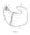
- Figur 1: ein Hörgerät in perspektivischer Darstellung unter Weglassung der elektrischen Bauteile, bei welchem der erfindungsgemässe Bügel einstückig mit dem Gehörgangteil gefertigt ist;
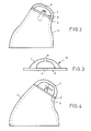
- Figur 2: ein Hörgerät in Seitenansicht bei dem im Bügel mit Grundplatte aufgeklebt und angepasst ist;
- Figur 3: eine Seitenansicht eines Bügels mit Grundplatte in unbearbeiteter Form;
- Figur 4: eine weitere Ausführung eines Hörgerätes bei dem der Bügel und die Grundplatte getrennt angebracht werden;
- Figur 5: mehrere Grundplatten in Streifenform gefertigt und
- Figur 6: mehrere Bügel die zusammenhängend in Stabform gegossen sind;
- Figur 7: einen Schnitt durch einen Bügel gemäss Figur 6 entlang der Linie X-X.
- In den Zeichnungen ist mit 1 ein Hörgerät bezeichnet, das im wesentlichen aus einem Ohrmuschelteil 2 und einem Gehörgangteil 3 besteht. Das Gehörgangteil 3 endet endseitig in einer Endseite 5, die im wesentlichen flach ausgebildet ist und in der eine Durchführungsbohrung angebracht ist.
- Die Schallaustrittsöffnung wird durch einen Rohrabschnitt 6, beispielsweise einem Plastikschlauch gebildet, der als Schallkanal in Richtung zum Trommelfell führt und der über die Endseite 5 nach oben hin vorsteht, so dass die Durchführungsbohrung beim Reinigen der Endseite 5, beispielsweise mit einer Bürste, überhaupt nicht mit der Bürste in Berührung kommt.
- Der Rohrabschnitt 6 wird von einem Bügel 7 übergriffen, der abgerundet und damit anatomisch korrekt gestaltet ist und der in dieser Ausführungen materialeinheitlich aus der Wandung des Gehörgangteiles ausgeformt ist. Dieser Bügel 7 weist in seinem Scheitelpunkt gegenüberliegend der Schallaustrittsöffnung 4 des Rohrabschnittes 6 eine Bohrung 8 auf, die als Schallbohrung dient.
- Es ist erkennbar, dass es mit der neuen Einrichtung möglich ist, ein leichtes Entfernen des sich im Bereich der Endseite 5 ansetzenden Cerumens zu berwirken. Weiterhin ist ein Lösen von Bauteilen bei Entnahme des Hörgerätes aus dem Ohr nicht möglich.
- Eine komplizierte Handhabung irgendwelcher entnehmbarer Bauteile wird vermieden, so dass das Hörgerät auch von älteren Personen problemlos instandgehalten werden kann. Ueber diese Vorteile hinaus wird erreicht, dass ein dif fuser Schallaustritt gewährleistet wird, der dem normalen Schallempfinden des Menschen besser entspricht als ein gerichteter Schallaustritt, wie er in vielen Hörgeräten noch üblich ist.
- In den technischen Labors für Hörgeräte müssen die Ohrmuschel- und Gehörgangteile in Einzelanfertigung dem jeweiligen Patienten angepasst werden. In der besprochenen Ausführung nach Figur 1 ist der Bügel 7 einteilig aus demselben Material hergestellt aus dem der Gehörgangteil besteht. Eine solche Fertigung ist jedoch relativ aufwendig zudem fehlt eine Kennzeichnung der Hörgeräte. Dies kann gelegentlich zu Seitenverwechslungen durch die Hörgerätträger führen. Es ist daher vorteilhaft eine Ausführung gemäss der Figur 2 zu verwenden. Bei dieser Variante wird vorerst das individuell an den Benützer angepasste Gehörgangteil 3 gefertigt und danach das Ende flach abgeschliffen. Dies ergibt eine offene, ebene Endseite 5. Hierauf wird nun ein seriengefertigtes Element 10, welches aus einem Grundplättchen 11 mit Bügel 7 besteht (Fig. 3) aufgeklebt. Vorgängig kann zumindest die Durchführungsbohrung 4 im Grundplättchen 11 gebohrt werden. Schliesslich kann auch die Bohrung 8 im Bügel angebracht werden. Die über die Endseite 5 vorstehenden Teile müssen nur noch abgeschliffen werden. Die Grundplättchen 11 mit Bügel 7 lassen sich serienmässig giessen oder spritzen aus einem physiologisch unbedenklichen Kunststoff. Dabei lässt sich der Kunststoff in den beiden audiometrischen Farben einfärben, so dass dadurch die Hörgeräte für links und rechts unterschiedlich individualisiert sind. Diese Lösung bringt zwar erhebliche fertigungstechnische Vorteile und Kosteneinsparungen, hat aber immer noch geringfügige Probleme. Zum einen muss jedes Grundplättchen 11 mit Bügel 7 einzeln gegossen beziehungsweise gespritzt werden. Ferner ist das ganze Element 10 gesamthaft eingefärbt, wodurch die Sichtkontrolle bezüglich einer Verschmutzung erschwert ist und schliesslich müssen zwei verschiedenfarbige Element 10 an Lager gehalten werden.
- Diese Nachteile vermeidet die Ausführung gemäss den Figuren 4-7. Gleich wie bei der Ausführung gemäss Figur 2 wird wiederum der Gehörgangteil 3 flach abgeschliffen um eine Endseite 5 zu bilden. Hierauf wird nun nicht ein ganzes Element, sondern lediglich ein farbiges Grundplättchen 11' geklebt. Auf das Grundplättchen 11 klebt' man anschliessend einen Bügel 7' aus farblosem, transparentem Kunststoff. Diese Variante behebt die vorgenannten Nachteile und ist besonders für die Fertigung in Gross-Serien geeignet. Hierzu seien die einzelnen Elemente nochmals kurz beschrieben.
- Die farbigen Grundplättchen 11' werden zu Streifen 12 mit Sollbruchstellen 13 unterteilt, gestanzt. Gleichzeitig wird jedes Plättchen 11' mit einer ebenfalls eingestanzten Mittemarkierung 14 für die Durchführungsbohrung 4 versehen. Der Hörgerätetechniker versieht somit die Endseite 5 mit einem Schnellkleber, nimmt den Streifen 12 zur Hand und drückt das äusserste Grundplättchen 11' auf die Endseite 5. Nach wenigen Sekunden bricht er den verbleibenden Steifen entlang der angrenzenden Sollbruchstelle 13 ab. Nun kann er bequem an der markierten Stelle 14 die Durchführungsbohrung 4 anbringen und den Rohrabschnitt 6 einführen. Auch die Bügel 7' sind beispielsweise in Form von Streifen von 10 Stück zusammenhängend gefertigt. Auf diese Weise kann mit einer Einfachform ein Streifen von 10 Bügel pro Spritz- oder Giessvorgang gefertigt werden. In Figur 6 ist ein solcher Streifen 15 dargestellt, wobei die Bügel 7' mit der konkaven Wölbung nach oben sichtbar sind.
- Der zwischen je zwei benachbarten, sowie seitlich verbleibende Trägermaterial 16 dient als Sollbruchbereich. Ueberhöht vorstehend sind die Bügelabstützflächen 17, die als Klebflächen dienen.
- Aehnlich wie zuvor beschrieben werden als nächstes die Bügelabstützflächen 17 mit Schnellkleber bestrichen und auf das bereits aufgeklebte Grundplättchen 11'gedrückt. Nach wenigen Sekunden ist die Haftkraft so gross, dass der verbleibende Teil des Streifens 15 abgebrochen werden kann. Schliesslich müssen nur noch die vorstehenden Teile der Grundplättchen und der Bügel 7', beispielsweise etwa entlang den gestrichelten Linien 10 (Figur 7) abgeschliffen werden.
- Ein derart gefertigtes Hörgerät hat alle vorgenannten Vorteile. Es lässt scih serienmässig preiswert fertigen und die Grundplättchen können in den gewünschten audiometrischen Farben rot für rechts und blau für links herstellen. Bezüglich der lichten Weite des Bügels, das heisst, die Grösse der Wölbung gelten vorzugsweise folgende Masse: Breite ca. 3,8mm - 5,Omm, Höhe minimal 1,5mm. Diese Masse ergeben sich aus den Bedingungen des Gehörganges, sowie aus der Erfahrung der Kornbildung der Cerume.
Claims (10)
Priority Applications (1)
| Application Number | Priority Date | Filing Date | Title |
|---|---|---|---|
| AT89810014T ATE99104T1 (de) | 1988-01-27 | 1989-01-10 | Hoergeraet. |
Applications Claiming Priority (2)
| Application Number | Priority Date | Filing Date | Title |
|---|---|---|---|
| DE3802250A DE3802250C1 (de) | 1988-01-27 | 1988-01-27 | |
| DE3802250 | 1988-01-27 |
Publications (3)
| Publication Number | Publication Date |
|---|---|
| EP0326513A2 true EP0326513A2 (de) | 1989-08-02 |
| EP0326513A3 EP0326513A3 (de) | 1991-05-29 |
| EP0326513B1 EP0326513B1 (de) | 1993-12-22 |
Family
ID=6346020
Family Applications (1)
| Application Number | Title | Priority Date | Filing Date |
|---|---|---|---|
| EP89810014A Expired - Lifetime EP0326513B1 (de) | 1988-01-27 | 1989-01-10 | Hörgerät |
Country Status (5)
| Country | Link |
|---|---|
| US (1) | US4945569A (de) |
| EP (1) | EP0326513B1 (de) |
| AT (1) | ATE99104T1 (de) |
| CA (1) | CA1318857C (de) |
| DE (2) | DE3802250C1 (de) |
Cited By (3)
| Publication number | Priority date | Publication date | Assignee | Title |
|---|---|---|---|---|
| DE4140850C1 (en) * | 1991-12-11 | 1993-06-24 | Siemens Audiologische Technik Gmbh, 8520 Erlangen, De | Cerumen protection for in-ear hearing aid - uses hoop secured to housing of hearing aid via cooperating screw threads to protect sound exit opening |
| DE19843389C2 (de) * | 1998-09-22 | 2002-07-11 | Fariborz-Hassan Dirinpur | Perforierte Otoplastik für Hörgeräte |
| DE102020205439A1 (de) | 2020-04-29 | 2021-11-04 | Sivantos Pte. Ltd. | Hörvorrichtung |
Families Citing this family (16)
| Publication number | Priority date | Publication date | Assignee | Title |
|---|---|---|---|---|
| USD338530S (en) | 1991-09-20 | 1993-08-17 | Audio Science, Inc. | Hearing aid |
| US5327500A (en) * | 1992-12-21 | 1994-07-05 | Campbell Donald E K | Cerumen barrier for custom in the ear type hearing intruments |
| USD355702S (en) | 1992-12-28 | 1995-02-21 | Johnson Ronald D | Filter for attachment to an in-ear hearing aid to prevent the migration of ear wax into the hearing aid |
| USD375556S (en) | 1994-06-27 | 1996-11-12 | Rion Kabushiki Kaisha | Hearing aid |
| US5572594A (en) * | 1994-09-27 | 1996-11-05 | Devoe; Lambert | Ear canal device holder |
| US5982908A (en) * | 1997-12-22 | 1999-11-09 | Bauman; Natan | Ear wax collection device for a hearing aid |
| US6134333A (en) * | 1998-03-17 | 2000-10-17 | Sonic Innovations, Inc. | Disposable oleophobic and hydrophobic barrier for a hearing aid |
| US6105713A (en) * | 1998-09-17 | 2000-08-22 | Sonic Innovations, Inc. | Cover movable by rotation forming a cerumen barrier in a hearing aid |
| US20040105562A1 (en) * | 2001-03-16 | 2004-06-03 | Jaromir Kulman | Housing for a hearing aid |
| US7471800B2 (en) | 2004-03-29 | 2008-12-30 | In'tech Industries, Inc. | Wax barrier system |
| DE102006008044B3 (de) * | 2006-02-21 | 2007-05-10 | Siemens Audiologische Technik Gmbh | Im Ohr tragbares Hörhilfegerät mit einem Belüftungskanal |
| DE102008038213B8 (de) | 2008-08-18 | 2010-02-11 | Siemens Medical Instruments Pte. Ltd. | Hörhilfegerät mit einer Wandlerschutzeinrichtung |
| US8761424B2 (en) | 2009-06-22 | 2014-06-24 | Shure Acquisition Holdings, Inc. | Earphone sleeve assembly having integral barrier |
| JP6286934B2 (ja) * | 2013-08-22 | 2018-03-07 | 株式会社ジェイテクト | フレキシブル生産システム |
| USD735169S1 (en) * | 2014-06-23 | 2015-07-28 | Martie Shieh | Housing of an in-ear earphone |
| EP3570561A1 (de) * | 2018-05-17 | 2019-11-20 | Oticon A/s | Cerumenfilter für einen lautsprecher eines hörgeräts |
Family Cites Families (5)
| Publication number | Priority date | Publication date | Assignee | Title |
|---|---|---|---|---|
| US3209382A (en) * | 1963-04-17 | 1965-10-05 | Richard L Scott | Life-preserver combination |
| DE1979669U (de) * | 1967-10-03 | 1968-02-29 | Bosch Elektronik Photokino | Im ohr zu tragendes schwerhoerigengeraet. |
| CH528198A (de) * | 1971-12-30 | 1972-09-15 | Elektroakustik Ag F | Hörgerät |
| FR2596644A1 (fr) * | 1986-04-08 | 1987-10-09 | Philips Massiot Mat Medic | Appareil de prothese auditive logeable dans un conduit auditif |
| DE8610634U1 (de) * | 1986-04-18 | 1986-07-17 | Borowsky, Hans-Dieter, 4400 Münster | Hörgerät |
-
1988
- 1988-01-27 DE DE3802250A patent/DE3802250C1/de not_active Expired
-
1989
- 1989-01-10 EP EP89810014A patent/EP0326513B1/de not_active Expired - Lifetime
- 1989-01-10 DE DE89810014T patent/DE58906462D1/de not_active Expired - Fee Related
- 1989-01-10 AT AT89810014T patent/ATE99104T1/de not_active IP Right Cessation
- 1989-01-26 US US07/302,418 patent/US4945569A/en not_active Expired - Fee Related
- 1989-01-26 CA CA000589282A patent/CA1318857C/en not_active Expired - Fee Related
Cited By (4)
| Publication number | Priority date | Publication date | Assignee | Title |
|---|---|---|---|---|
| DE4140850C1 (en) * | 1991-12-11 | 1993-06-24 | Siemens Audiologische Technik Gmbh, 8520 Erlangen, De | Cerumen protection for in-ear hearing aid - uses hoop secured to housing of hearing aid via cooperating screw threads to protect sound exit opening |
| DE19843389C2 (de) * | 1998-09-22 | 2002-07-11 | Fariborz-Hassan Dirinpur | Perforierte Otoplastik für Hörgeräte |
| DE102020205439A1 (de) | 2020-04-29 | 2021-11-04 | Sivantos Pte. Ltd. | Hörvorrichtung |
| US11729558B2 (en) | 2020-04-29 | 2023-08-15 | Sivantos Pte. Ltd. | Hearing device |
Also Published As
| Publication number | Publication date |
|---|---|
| DE3802250C1 (de) | 1988-10-27 |
| DE58906462D1 (de) | 1994-02-03 |
| US4945569A (en) | 1990-07-31 |
| EP0326513B1 (de) | 1993-12-22 |
| ATE99104T1 (de) | 1994-01-15 |
| CA1318857C (en) | 1993-06-08 |
| EP0326513A3 (de) | 1991-05-29 |
Similar Documents
| Publication | Publication Date | Title |
|---|---|---|
| EP0326513B1 (de) | Hörgerät | |
| DE3851292T2 (de) | Ausgabegerät für Hörgerätwachsfilterelemente. | |
| DE69324571T2 (de) | Cerumensperre für hörgeräte | |
| DE3413067C1 (de) | Gehoergangseitiges Hoergeraete-Otoplastik-Endstueck und Hoergeraete-Otoplastik | |
| DE8323464U1 (de) | Am Ohr zu tragendes Hörgerät | |
| DE29918139U1 (de) | Otoplastik für Hinter-dem-Ohr (HdO)-Hörgeräte | |
| DE2452093A1 (de) | Auswechselbare schutzmanschette fuer ohrenschutzmuscheln | |
| EP0433348A1 (de) | Cerumenfänger für schwerhörigengeräte. | |
| EP0186748A2 (de) | Hörgerät zum Tragen im Ohr oder im Ohrkanal | |
| EP0639932B1 (de) | Hinter dem Ohr zu tragendes Hörhilfegerät | |
| EP0288822A1 (de) | Hinter-dem-Ohr-Hörgerät | |
| EP1865749A2 (de) | Abdeckvorrichtung für Hörgerät-Gehäuseanordnung | |
| EP0244671A1 (de) | Verfahren und Vorrichtung zur Durchführung einer akustischen Vergleichsmessung | |
| WO2002015829A1 (de) | Gehörschutzstöpsel | |
| WO2002071969A1 (de) | Zahnprothese mit saughalter | |
| DE4230308C1 (en) | Hearing aid carried behind ear - has stirrup formed on housing frame carrying electrical and electromechanical components | |
| DE1287137B (de) | Im Ohr zu tragendes Schwerhoerigengeraet | |
| DE3301927C1 (de) | Hörhilfsgerät für Schwerhörige und Hörbehinderte | |
| DE2802602C2 (de) | ||
| DE3936062A1 (de) | Verfahren zum herstellen einer otoplastik fuer ein modulares, im ohr zu tragendes hoergeraet | |
| DE10138613B4 (de) | Belüftungssystem für Otoplastiken | |
| DE60203540T2 (de) | Hörgerätanordnung | |
| EP0245742B1 (de) | Verfahren und Vorrichtung zur Herstellung einer Otoplastik | |
| DE102014221590B4 (de) | Ohrstöpselset und Ohrstöpsel | |
| EP0512354A2 (de) | Hörhilfegerät in Form eines Ohrschmuckes |
Legal Events
| Date | Code | Title | Description |
|---|---|---|---|
| PUAI | Public reference made under article 153(3) epc to a published international application that has entered the european phase |
Free format text: ORIGINAL CODE: 0009012 |
|
| AK | Designated contracting states |
Kind code of ref document: A2 Designated state(s): AT CH DE ES FR GB IT LI NL SE |
|
| PUAL | Search report despatched |
Free format text: ORIGINAL CODE: 0009013 |
|
| AK | Designated contracting states |
Kind code of ref document: A3 Designated state(s): AT CH DE ES FR GB IT LI NL SE |
|
| 17P | Request for examination filed |
Effective date: 19910430 |
|
| RAP3 | Party data changed (applicant data changed or rights of an application transferred) |
Owner name: KULMAN, JAROMIR |
|
| 17Q | First examination report despatched |
Effective date: 19930401 |
|
| GRAA | (expected) grant |
Free format text: ORIGINAL CODE: 0009210 |
|
| AK | Designated contracting states |
Kind code of ref document: B1 Designated state(s): AT CH DE ES FR GB IT LI NL SE |
|
| PG25 | Lapsed in a contracting state [announced via postgrant information from national office to epo] |
Ref country code: IT Free format text: LAPSE BECAUSE OF FAILURE TO SUBMIT A TRANSLATION OF THE DESCRIPTION OR TO PAY THE FEE WITHIN THE PRE;WARNING: LAPSES OF ITALIAN PATENTS WITH EFFECTIVE DATE BEFORE 2007 MAY HAVE OCCURRED AT ANY TIME BEFORE 2007. THE CORRECT EFFECTIVE DATE MAY BE DIFFERENT FROM THE ONE RECORDED.SCRIBED TIME-LIMIT Effective date: 19931222 Ref country code: GB Effective date: 19931222 Ref country code: NL Effective date: 19931222 Ref country code: ES Free format text: THE PATENT HAS BEEN ANNULLED BY A DECISION OF A NATIONAL AUTHORITY Effective date: 19931222 Ref country code: SE Effective date: 19931222 |
|
| REF | Corresponds to: |
Ref document number: 99104 Country of ref document: AT Date of ref document: 19940115 Kind code of ref document: T |
|
| ET | Fr: translation filed | ||
| REF | Corresponds to: |
Ref document number: 58906462 Country of ref document: DE Date of ref document: 19940203 |
|
| NLV1 | Nl: lapsed or annulled due to failure to fulfill the requirements of art. 29p and 29m of the patents act | ||
| GBV | Gb: ep patent (uk) treated as always having been void in accordance with gb section 77(7)/1977 [no translation filed] |
Effective date: 19931222 |
|
| PLBE | No opposition filed within time limit |
Free format text: ORIGINAL CODE: 0009261 |
|
| STAA | Information on the status of an ep patent application or granted ep patent |
Free format text: STATUS: NO OPPOSITION FILED WITHIN TIME LIMIT |
|
| 26N | No opposition filed | ||
| PGFP | Annual fee paid to national office [announced via postgrant information from national office to epo] |
Ref country code: FR Payment date: 19941229 Year of fee payment: 7 |
|
| PG25 | Lapsed in a contracting state [announced via postgrant information from national office to epo] |
Ref country code: FR Effective date: 19960930 |
|
| REG | Reference to a national code |
Ref country code: FR Ref legal event code: ST |
|
| PGFP | Annual fee paid to national office [announced via postgrant information from national office to epo] |
Ref country code: AT Payment date: 19970130 Year of fee payment: 9 |
|
| PGFP | Annual fee paid to national office [announced via postgrant information from national office to epo] |
Ref country code: DE Payment date: 19970204 Year of fee payment: 9 |
|
| PGFP | Annual fee paid to national office [announced via postgrant information from national office to epo] |
Ref country code: CH Payment date: 19970430 Year of fee payment: 9 |
|
| PG25 | Lapsed in a contracting state [announced via postgrant information from national office to epo] |
Ref country code: AT Free format text: LAPSE BECAUSE OF NON-PAYMENT OF DUE FEES Effective date: 19980110 |
|
| PG25 | Lapsed in a contracting state [announced via postgrant information from national office to epo] |
Ref country code: LI Free format text: LAPSE BECAUSE OF NON-PAYMENT OF DUE FEES Effective date: 19980131 Ref country code: CH Free format text: LAPSE BECAUSE OF NON-PAYMENT OF DUE FEES Effective date: 19980131 |
|
| REG | Reference to a national code |
Ref country code: CH Ref legal event code: PL |
|
| PG25 | Lapsed in a contracting state [announced via postgrant information from national office to epo] |
Ref country code: DE Free format text: LAPSE BECAUSE OF NON-PAYMENT OF DUE FEES Effective date: 19981001 |