EP0326988A2 - Verfahren zum Bestimmen der Strahlungsverluste von Faserverbindungen - Google Patents
Verfahren zum Bestimmen der Strahlungsverluste von Faserverbindungen Download PDFInfo
- Publication number
- EP0326988A2 EP0326988A2 EP89101538A EP89101538A EP0326988A2 EP 0326988 A2 EP0326988 A2 EP 0326988A2 EP 89101538 A EP89101538 A EP 89101538A EP 89101538 A EP89101538 A EP 89101538A EP 0326988 A2 EP0326988 A2 EP 0326988A2
- Authority
- EP
- European Patent Office
- Prior art keywords
- optical fibers
- amount
- splice loss
- splice
- fusion
- Prior art date
- Legal status (The legal status is an assumption and is not a legal conclusion. Google has not performed a legal analysis and makes no representation as to the accuracy of the status listed.)
- Granted
Links
Images




Classifications
-
- G—PHYSICS
- G02—OPTICS
- G02B—OPTICAL ELEMENTS, SYSTEMS OR APPARATUS
- G02B6/00—Light guides; Structural details of arrangements comprising light guides and other optical elements, e.g. couplings
- G02B6/24—Coupling light guides
- G02B6/255—Splicing of light guides, e.g. by fusion or bonding
- G02B6/2555—Alignment or adjustment devices for aligning prior to splicing
-
- G—PHYSICS
- G01—MEASURING; TESTING
- G01B—MEASURING LENGTH, THICKNESS OR SIMILAR LINEAR DIMENSIONS; MEASURING ANGLES; MEASURING AREAS; MEASURING IRREGULARITIES OF SURFACES OR CONTOURS
- G01B11/00—Measuring arrangements characterised by the use of optical techniques
- G01B11/26—Measuring arrangements characterised by the use of optical techniques for measuring angles or tapers; for testing the alignment of axes
- G01B11/27—Measuring arrangements characterised by the use of optical techniques for measuring angles or tapers; for testing the alignment of axes for testing the alignment of axes
- G01B11/272—Measuring arrangements characterised by the use of optical techniques for measuring angles or tapers; for testing the alignment of axes for testing the alignment of axes using photoelectric detection means
-
- G—PHYSICS
- G01—MEASURING; TESTING
- G01M—TESTING STATIC OR DYNAMIC BALANCE OF MACHINES OR STRUCTURES; TESTING OF STRUCTURES OR APPARATUS, NOT OTHERWISE PROVIDED FOR
- G01M11/00—Testing of optical apparatus; Testing structures by optical methods not otherwise provided for
- G01M11/30—Testing of optical devices, constituted by fibre optics or optical waveguides
- G01M11/37—Testing of optical devices, constituted by fibre optics or optical waveguides in which light is projected perpendicularly to the axis of the fibre or waveguide for monitoring a section thereof
-
- G—PHYSICS
- G02—OPTICS
- G02B—OPTICAL ELEMENTS, SYSTEMS OR APPARATUS
- G02B6/00—Light guides; Structural details of arrangements comprising light guides and other optical elements, e.g. couplings
- G02B6/24—Coupling light guides
- G02B6/255—Splicing of light guides, e.g. by fusion or bonding
- G02B6/2551—Splicing of light guides, e.g. by fusion or bonding using thermal methods, e.g. fusion welding by arc discharge, laser beam, plasma torch
Definitions
- the present invention relates to a method for estimating a splice loss of a spliced section of a fusion-spliced optical fiber.
- the splice loss of a spliced section of an optical fiber is measured by a power monitor method. According to this method, light is permitted to pass through the optical fiber via the spliced section and the splice loss of the spliced section is measured from the amount of light received.
- a method for estimating a splice loss of a spliced portion of an optical fiber formed by fusion-splicing a pair of optical fibers through heat treatment comprises the step of: detecting an amount of axial deviation attained prior to or immediately after heating a pair of optical fibers and an amount of axial deviation attained upon completion of heat treatment on the optical fibers to provide a difference between the axial deviations; and measuring a splice loss originated from an opposite-phase core distortion based on the difference between the axial distortions.
- the term "immediately after heating a pair of optical fibers” indicates the time period from a point when the heat treatment has started to a point when, even if glass melts by the heat treatment, the surface tension of the melted glass has not yet worked sufficiently; the period is about 2 sec or less from the point when the heat treatment has started in the ordinary case involving spark heating.
- the term “prior to heating " means the time before the heat treatment has started or the time at which heat treatment has not started yet.
- a method for measuring a splice loss of a spliced portion of an optical fiber formed by fusion-splicing a pair of optical fibers through heat treatment comprises the step of: acquiring a splice loss from an amount of axial deviation upon completion of heat treatment on a pair of optical fibers, a splice loss from an amount of angular deviation upon completion of heat treatment on the optical fibers, and a splice loss originated from opposite-phase core distortion from a difference between an amount of axial deviation attained prior to and an amount of axial deviation attained upon completion of heat treatment on the optical fibers; and measuring an entire splice loss by adding the splice losses obtained in the splice-loss acquiring step.
- the axial deviation means a deviation of axes of fibers 11 and 12, i.e. a deviation of outer configurations of fibers 11 and 12, which is caused by fusion-splicing optical fibers 11 and 12 with their axes deviating from each other, as shown in Fig. 1A.
- Such an axial deviation occurs if the axes of the optical fibers 11 and 12, when butted against each other, are not aligned and heating is not sufficient.
- the angular deviation is caused by misalignment of ends of the optical fibers 11 and 12 and an excess amount of mutual pressing of these optical fibers, as shown in Fig. 1B.
- ⁇ is a deviation angle
- n2 is a refractive index of fiber core 21 and fiber core 22
- ⁇ is the wavelength of light
- W is the spot size
- the opposite-phase core distortion is a bending of the cores 21 and 22 in the opposite direction at the spliced portion as shown in Fig. 1C, and it is caused if the axes of the optical fibers 11 and 12 when butted are misaligned and sufficient heat is applied to the fibers under this condition. More specifically, when the optical fibers 11 and 12 having their axes misaligned, are heated in this state to a certain degree, a step would be formed at the exterior of the spliced portion as shown in Fig. 2A. If heat is further applied, the step portion would disappear due to the surface tension. At this time, the cores 21 and 22 are bent at the spliced portion as shown in Fig. 2B.
- the in-phase core distortion is the bending of the cores 21 and 22 in the same direction at the spliced portion as shown in Fig. 1D.
- This distortion is caused by misalignment of the cleaved angles of fiber ends to be spliced and an insufficient amount of the optical fibers pressed.
- the misalignment of the cleaved angles of the fiber ends is significant or the amount of the fibers pressed is insuff icient to thereby form a neck portion or a small-diameter portion at the spliced portion, the fibers melt when heated and flow in the neck portion, thus bending the cores 21 and 22.
- the opposite-phase core distortion occurs in the process as shown in Figs. 2A and 2B.
- the amount of deviation is measured before or immediately after the heat treatment, and the amount of deviation is again measured upon completion of the heat treatment, and the difference Y between these deviation amounts is then acquired.
- This difference Y is the amount of core distortion.
- the amount Y can be considered to be index for measuring the splice loss.
- the acquired data includes the entire splice loss originated from axial deviation, opposite-phase core distortion and in-phase core distortion. Since the in-phase core distortion significantly increases the splice loss, however, measuring the entire splice loss including the one caused by this deviation should undesirably reduce the measuring accuracy. In this respect, therefore, data acquired from the spliced section at which the in-phase deviation occurred was eliminated.
- the entire splice loss in this case is the sum of the splice losses caused by the axial deviation, angular deviation and opposite-phase core distortion, and the measured splice loss data represents the splice loss including these three types of splice losses.
- splice loss caused by the opposite-phase core distortion can be attained by subtracting these two splice losses from the actually acquired data.
- a pair of ribbon type optical fibers each having four single-mode optical fibers were used.
- the core fibers of this pair of optical fibers were fusion-spliced together and the splice losses were measured using the power monitor method. From the acquired data, the total splice loss was measured based on the measuring method according to this invention.
- an apparatus for monitoring the spliced portion of the optical fiber from two directions was used to observe the external deviation amount of the spliced portion from two directions (X and Y directions) normal to the axes (i.e., Z axes) of the optical fibers.
- the amount of the axial deviation was measured immediately after heat was applied for fusion-splicing the fibers and was again measured after the heat treatment was completed, the difference Y between these two deviation amounts was attained, and the splice loss was measured from this difference Y.
- the above measurement was executed for both of the case where fibers having their ends cleaved by the proper cutter were fusion-spliced and the case where fibers having their ends cleaved by an intentionally unadjusted cutter.
- the reason for using those fibers with their ends cleaved by the unadjusted cutter is to generate many defective spliced portions and to effectively evaluate the measuring function of this invention.
- Fig. 5 is a histogram of the splice losses (measured by the power monitor method) of the spliced portions formed by fusion-splicing those optical fibers having their ends cleaved by the proper cutter.
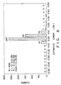
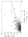
- Fig. 6 is a histogram of the errors (estimated errors) of the estimated losses (total) with respect to the splice losses. The relation between the splice losses and the estimated losses is illustrated in Fig. 7. From these, good results were attained with the average of the estimated error being -0.002 dB and the standard deviation being 0.04 dB.
- Fig. 8 is a histogram of the splice losses of the spliced portions formed by fusion-splicing those optical fibers having their ends cleaved by the unadjusted cutter.
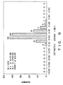
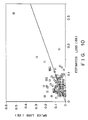
- Fig. 9 is a histogram of the estimated errors of this case, and Fig. 10 illustrates the relation between the splice losses and the estimated losses.
- the average of the estimated error was 0.013 dB and the standard deviation was 0.04 dB, about the same values as those obtained in the former case involving the optical fibers with their ends cleaved by the proper cutter.
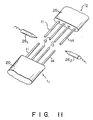
- ribbon type optical fibers 11 and 12 each have a tape-like shape, and each comprise four parallel single-mode optical fibers 11 to 14. Protection jackets 2 are removed from those ends of the parallel fibers 11-l4 of the optical fibers 11 and 12, which are to be fusion-spliced.
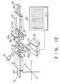
- Adapter 21 is accommodated in a guide groove (not shown) formed in the body (not shown) of the apparatus.
- Optical fibers 11-l4 of each of optical fibers 11 and 12 are set in V-grooves (not shown) of V-groove block 22 mounted on the apparatus body, so that the end faces of optical fibers 11-14 of one optical fiber 11 are opposed to the end faces of optical fibers 11-l4 of the other optical fiber 12.
- Adapters 21 are then moved in Z direction (Fig.
- the optical fibers 11-14 of the optical fibers 11 and 12 are moved toward.
- the amount of the axial deviation Dx1 beween the optical fibers 11-14 of one optical fibers 11 and the optical fibers 11-l4 of the other optical fibers 12 are measured, by monitoring the X images of the optical fibers 11-14 using microscope 23, TV camera 24, and TV monitor 25.
- adapters 21 are further moved toward in Z direction and abutted against each other, so that the optical fibers 11-14 are completely fusion-spliced.
- the amount of the axial deviation Dx2 between the optical fibers 11-14 of one optical fibers 11 and the optical fibers 11-14 of the other optical fibers 12 is measured, by monitoring the X images of the optical fibers 11-14 using microscope 23, TV camera 24, and TV monitor 25.
- deviations Dy1 and Dy2 in Y images corresponding to deviations Dx1 and Dx2 are measured.
- ⁇ Dx12 + Dy12 deviation D1 which is immediatly after heat is applied can be obtained.
- ⁇ Dx22 + Dy22 deviation D2 which is after the fibers are completely spliced can be obtained. Thereafter, the difference between deviations D1 and D2 are calculated to provide a core distortion of the fibers.
- Deviations Dx1 and Dy1 may be measured prior to applying an arc to the fibers.
- illuminating lights l1 and l2 are emitted from light source 27 (Fig. 12).
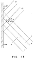
- Lights l1 and l2 are directed in a direction shifted by 45° from the normal direction of a plane which is formed by the optical fibers 11-14.
- Illuminating light l1 is reflected by reflecting mirror 28 and then passed through optical fibers 11-14.
- Illuminating light l2 is passed through optical fibers 11-14 and then reflected by reflecting mirror 28.
- the reflected light l1 is picked up by TV camera 24 through microscope 23 and transferred to TV monitor 25 to display images X of the optical fibers 11-12 on the monitor screen.
- microscope 23 and TV camera 24 are slightly moved.
- the reflected light l2 is picked up by TV camera 24 through microscope 23 and transferred to TV monitor 25 to display images Y of the optical fibers 11-12 on the monitor screen.
- Fig. 14 single type optical fibers 101 and 102 are shown, together with a fusion splicing apparatus. Protection jackets are removed for fusion-splice.
- Optical fibers 11 and 12 are supported in V-grooves of V-groove members 321 and 322 to oppose each other in the Z direction (Fig. 14). Thereafter, an abutment rod or a stopper (not shown) is located between optical fibers 11 and 12, and optical portions 11 and 12 are moved closed to each other in the Z direction until fiber portions 11 and 12 are brought into contact with the stopper, thereby setting an initial distance between fiber portions 11 and 12. Thereafter, stopper is removed.
- heat of an arc discharge is applied via discharge electrodes 261 and 262 to the ends of the optical fibers 11 and 12 to round the fiber ends so that the fiber ends may be strongly fusion-spliced at the following spliced step.
- heat of an arc discharge is applied via discharge electrode 261 and 262 to the ends of the optical fibers 11 and 12, while the optical fibers are moved toward.
- the amount of the axial deviation Dx1 between the optical fibers 11 and 12 is measured, by monitoring the X image of the optical fibers 11 and 12 using microscope 23, TV camera 24, and TV monitor 25.
- the optical fibers 11 and 12 After, while further applying an arc to the ends of the optical fibers 11 and 12, the optical fibers are further moved toward in the Z direction and abutted against each other, so that optical fibers are completely fusion-spliced. After the optical fibers 11 and 12 are completely fusion-spliced, that is, the heat treatment is completed, the amount of the axial deviation Dx2 between the optical fibers 11 and 12 is measured, by monitoring the X image of the optical fibers 11 and 12 using microscope 23, TV camera 24, and TV monitor 25.
- Deviations Dx1 and Dy1 may be measured prior to applying an arc to the fibers.
- two light sources 32 and 34 are used to emit X-direction light Lxx and Y-direction light Lxy, respectively.
- Light Lxx is passed through the fiber ends in X-direction and picked up through microscope 23 by TV camera 24.
- Light Lxy is first passed through the fiber ends in Y-direction, then reflected by reflecting mirror 28, and finally picked up through microscope 23 by TV camera 24.
- TV monitor 25 displays the X and Y images of the fiber ends on the monitor screen based on the picked up lights by TV camera 24.
- the estimated losses originated from the opposite-phase core distortion were attained from the difference between the amounts of axial deviation immediately after the fusion-splicing and upon completion of the heat treatment. With a slight error allowed, however, it is possible to measure the amount of axial deviation before the heat application and use this value. In other words, although the amount of the axes of the fibers deviated by the pressing force applied thereto at the time of fusion-splicing becomes an error in this case, it is possible to eliminate the measurement immediately after the heat application.
- the splice loss originated from the opposite-phase core distortion and the total splice loss can be measured with a high accuracy by observing the outline of the spliced section.
- This method can ensure easy detection of defective spliced portions, and is therefore suitable for field works where the fibers are installed.
- the use of this method in fusion-splicing ribbon type optical fibers together can further improve the efficiency of the splicing works.
Landscapes
- Physics & Mathematics (AREA)
- General Physics & Mathematics (AREA)
- Engineering & Computer Science (AREA)
- Plasma & Fusion (AREA)
- Optics & Photonics (AREA)
- Chemical & Material Sciences (AREA)
- Analytical Chemistry (AREA)
- Mechanical Coupling Of Light Guides (AREA)
- Testing Of Optical Devices Or Fibers (AREA)
Applications Claiming Priority (2)
| Application Number | Priority Date | Filing Date | Title |
|---|---|---|---|
| JP63020022A JPH0675023B2 (ja) | 1988-01-30 | 1988-01-30 | 光ファイバの接続損失推定法 |
| JP20022/88 | 1988-01-30 |
Publications (3)
| Publication Number | Publication Date |
|---|---|
| EP0326988A2 true EP0326988A2 (de) | 1989-08-09 |
| EP0326988A3 EP0326988A3 (en) | 1990-02-14 |
| EP0326988B1 EP0326988B1 (de) | 1992-08-05 |
Family
ID=12015464
Family Applications (1)
| Application Number | Title | Priority Date | Filing Date |
|---|---|---|---|
| EP89101538A Expired EP0326988B1 (de) | 1988-01-30 | 1989-01-30 | Verfahren zum Bestimmen der Strahlungsverluste von Faserverbindungen |
Country Status (5)
| Country | Link |
|---|---|
| US (1) | US4978201A (de) |
| EP (1) | EP0326988B1 (de) |
| JP (1) | JPH0675023B2 (de) |
| CA (1) | CA1309773C (de) |
| DE (1) | DE68902321T2 (de) |
Cited By (5)
| Publication number | Priority date | Publication date | Assignee | Title |
|---|---|---|---|---|
| EP1014070A3 (de) * | 1998-12-18 | 2000-07-05 | TELEFONAKTIEBOLAGET L M ERICSSON (publ) | Bewertung der Spleissverluste mittels Bildverarbeitung |
| DE19940775A1 (de) * | 1999-08-27 | 2001-03-01 | Siemens Ag | Verfahren und Vorrichtung zur Bestimmung der Qualität einer Verbindung zwischen Lichtwellenleitern |
| WO2002082137A1 (en) * | 2001-04-06 | 2002-10-17 | Telefonaktiebolaget L M Ericsson | Automatic optimization of a splice loss estimator for optical fiber splicers |
| EP1385029A1 (de) * | 2001-03-23 | 2004-01-28 | Sumitomo Electric Industries, Ltd. | Verfahren zum thermischen Spleissen optischer Fasern |
| WO2007077419A1 (en) * | 2006-01-05 | 2007-07-12 | University Of Southampton | Optical fibre with angled core |
Families Citing this family (20)
| Publication number | Priority date | Publication date | Assignee | Title |
|---|---|---|---|---|
| US5222172A (en) * | 1990-12-18 | 1993-06-22 | Fujikura, Ltd. | Multi-core single mode type optical fiber cable and method therefor |
| US5161207A (en) * | 1991-03-18 | 1992-11-03 | Hughes Aircraft Company | Optical fiber circumferentialy symmetric fusion splicing and progressive fire polishing |
| GB9117761D0 (en) * | 1991-08-16 | 1991-10-02 | Bicc Plc | Optical fibre splicing |
| US5299274A (en) * | 1992-06-25 | 1994-03-29 | Hughes Aircraft Company | Optical fiber laser fusion splicer |
| JP3049697B2 (ja) * | 1992-07-29 | 2000-06-05 | 住友電気工業株式会社 | モードフィールド径変換ファイバ |
| DE59309338D1 (de) * | 1992-08-07 | 1999-03-11 | Siemens Ag | Verfahren zur Ermittlung der Lage von Lichtwellenleitern und Einrichtung zur Durchführung des Verfahrens |
| JP3500850B2 (ja) * | 1996-04-23 | 2004-02-23 | 住友電気工業株式会社 | リボン型光ファイバの突き合せ部を観察する方法及び観察装置 |
| SE516153C2 (sv) * | 1997-02-14 | 2001-11-26 | Ericsson Telefon Ab L M | Förfarande och anordning vid hopsvetsning av optiska fibrer |
| DE19927583A1 (de) * | 1999-06-16 | 2000-12-21 | Siemens Ag | Verfahren zur Bestimmung der Dämpfung eines zwei optische Wellenleiter verbindenden Spleißes |
| US20040062495A1 (en) * | 2002-09-26 | 2004-04-01 | Sumitomo Electric Industries, Ltd. | Optical fiber product and method of fabricating thereof, Raman amplifier and method of fabricating thereof, method of fabricating of optical coupler, and optical transmission line |
| US7004640B2 (en) * | 2003-03-24 | 2006-02-28 | Aurora Instruments, Inc. | Low profile local injection and detection system for optical fiber waveguides |
| US7070342B2 (en) * | 2003-03-24 | 2006-07-04 | Aurora Instruments, Inc. | Low profile system for joining optical fiber waveguides |
| US7090414B2 (en) * | 2003-03-25 | 2006-08-15 | Aurora Instruments, Inc. | Automatic apparatus for cleaving optical fiber waveguides |
| US6984077B2 (en) * | 2003-03-25 | 2006-01-10 | Aurora Instruments, Inc. | System for joining polarization-maintaining optical fiber waveguides |
| US20120050523A1 (en) * | 2010-08-31 | 2012-03-01 | Cook Ian D | Method of inspecting an optical fiber junction |
| CN108369315B (zh) * | 2015-09-24 | 2020-08-04 | 恩耐公司 | 用于控制光束参数积的装置和方法 |
| CN107655507B (zh) * | 2017-09-27 | 2019-10-22 | 北京空间机电研究所 | 一种焦平面弧形拼接方法 |
| KR102774396B1 (ko) * | 2022-08-16 | 2025-02-27 | (주)파이버폭스 | 인공 지능을 활용한 광 선로 작업 검증 장치 및 방법 |
| WO2026141397A1 (ja) * | 2024-12-26 | 2026-07-02 | 住友電気工業株式会社 | 融着接続方法および融着接続機 |
| CN122171169B (zh) * | 2026-05-11 | 2026-08-04 | 浙江融汇通信设备有限公司 | 光缆分纤箱内光纤熔接损耗控制检测方法与系统 |
Family Cites Families (10)
| Publication number | Priority date | Publication date | Assignee | Title |
|---|---|---|---|---|
| US4179186A (en) * | 1978-03-31 | 1979-12-18 | Bell Telephone Laboratories, Incorporated | Apparatus and method of splicing optical fibers |
| US4274707A (en) * | 1979-06-14 | 1981-06-23 | Northern Telecom Limited | Apparatus for fusion splicing of optical fibers |
| US4557556A (en) * | 1983-10-28 | 1985-12-10 | At&T Bell Laboratories | Method of fabricating an optical attenuator by fusion splicing of optical fibers |
| US4557557A (en) * | 1983-10-28 | 1985-12-10 | At&T Bell Laboratories | Method of making an optical fiber attenuator using a lossy fusion splice |
| US4636033A (en) * | 1984-05-14 | 1987-01-13 | At&T Bell Laboratories | Optical fiber splice and methods of making |
| CA1262304A (en) * | 1985-06-28 | 1989-10-17 | John Charles Goodwin | Laser-fiber positioner |
| US4659217A (en) * | 1985-07-15 | 1987-04-21 | Raychem Corp. | Determining splice attenuation |
| GB8523157D0 (en) * | 1985-09-19 | 1985-10-23 | Bicc Plc | Optical fibre splicing |
| CA1264568A (en) * | 1986-04-23 | 1990-01-23 | Bell Canada | Method of determining optical fiber splice loss |
| US4812010A (en) * | 1987-02-06 | 1989-03-14 | Sumitomo Electric Industries, Ltd. | Apparatus for arranging a plurality of coated optical fibers and collective fusion splicing method using the apparatus |
-
1988
- 1988-01-30 JP JP63020022A patent/JPH0675023B2/ja not_active Expired - Lifetime
-
1989
- 1989-01-26 US US07/302,617 patent/US4978201A/en not_active Expired - Lifetime
- 1989-01-27 CA CA000589450A patent/CA1309773C/en not_active Expired - Lifetime
- 1989-01-30 EP EP89101538A patent/EP0326988B1/de not_active Expired
- 1989-01-30 DE DE8989101538T patent/DE68902321T2/de not_active Expired - Lifetime
Cited By (6)
| Publication number | Priority date | Publication date | Assignee | Title |
|---|---|---|---|---|
| EP1014070A3 (de) * | 1998-12-18 | 2000-07-05 | TELEFONAKTIEBOLAGET L M ERICSSON (publ) | Bewertung der Spleissverluste mittels Bildverarbeitung |
| DE19940775A1 (de) * | 1999-08-27 | 2001-03-01 | Siemens Ag | Verfahren und Vorrichtung zur Bestimmung der Qualität einer Verbindung zwischen Lichtwellenleitern |
| EP1385029A1 (de) * | 2001-03-23 | 2004-01-28 | Sumitomo Electric Industries, Ltd. | Verfahren zum thermischen Spleissen optischer Fasern |
| US6835005B2 (en) | 2001-03-23 | 2004-12-28 | Sumitomo Electric Industries, Ltd. | Method for fusion splicing optical fibers |
| WO2002082137A1 (en) * | 2001-04-06 | 2002-10-17 | Telefonaktiebolaget L M Ericsson | Automatic optimization of a splice loss estimator for optical fiber splicers |
| WO2007077419A1 (en) * | 2006-01-05 | 2007-07-12 | University Of Southampton | Optical fibre with angled core |
Also Published As
| Publication number | Publication date |
|---|---|
| DE68902321T2 (de) | 1993-01-14 |
| CA1309773C (en) | 1992-11-03 |
| US4978201A (en) | 1990-12-18 |
| JPH01196531A (ja) | 1989-08-08 |
| EP0326988A3 (en) | 1990-02-14 |
| DE68902321D1 (de) | 1992-09-10 |
| JPH0675023B2 (ja) | 1994-09-21 |
| EP0326988B1 (de) | 1992-08-05 |
Similar Documents
| Publication | Publication Date | Title |
|---|---|---|
| EP0326988B1 (de) | Verfahren zum Bestimmen der Strahlungsverluste von Faserverbindungen | |
| US6215555B1 (en) | Method and apparatus for measuring endface surface topography of multi-fiber fiberoptic connectors | |
| US9086538B2 (en) | Method for fusion splicing optical fibers | |
| US4544234A (en) | Low loss optical fiber splicing | |
| US6034718A (en) | Method and apparatus for observing tip portion of optical fibers butting each other | |
| US4945776A (en) | Method of testing spliced portion of optical fibers | |
| EP0320978B1 (de) | Verfahren zum Messen von an optische Fasern zugeführten Wärmemengen | |
| US20220352980A1 (en) | Communication apparatus identification device, optical fiber connection system, communication apparatus identification method, and optical fiber connection method | |
| US6718099B2 (en) | Pin insertion tool and method for measuring endface surface topography of multi-fiber fiberoptic connectors | |
| US4636033A (en) | Optical fiber splice and methods of making | |
| EP0740171A1 (de) | Fiberoptisches Dämpfungsglied | |
| EP0139171A2 (de) | Vorrichtung zum Ausrichten optischer Fibern | |
| JP2005284150A (ja) | コア拡大光ファイバの製造方法、光ファイバ、及び光コネクタ | |
| US20230296840A1 (en) | Splicing optical fibers to photonic integrated circuits | |
| JPS6049307A (ja) | フアイバ接続装置 | |
| Arrowsmith | Board-Level Optronics Assembly and Packaging | |
| JPH0526167B2 (de) | ||
| KR102824039B1 (ko) | 하이브리드 광섬유 융착 접속기 | |
| EP1130429A1 (de) | Methode und Apparat zum Ausrichten und Spleissen von optischen Fibern | |
| JPH0233107A (ja) | 光ファイバの融着接続装置 | |
| CN121115203A (zh) | 光纤、光纤连接器和电子设备 | |
| KR20240149048A (ko) | 광 패치 코드 제조방법 및 그 제조장치 | |
| GB2179145A (en) | Optical fibre end-face assessment | |
| JP2842627B2 (ja) | 光ファイバの多心一括融着接続方法 | |
| JPH095207A (ja) | 異径コア光ファイバの融着接続部の評価方法 |
Legal Events
| Date | Code | Title | Description |
|---|---|---|---|
| PUAI | Public reference made under article 153(3) epc to a published international application that has entered the european phase |
Free format text: ORIGINAL CODE: 0009012 |
|
| 17P | Request for examination filed |
Effective date: 19890130 |
|
| AK | Designated contracting states |
Kind code of ref document: A2 Designated state(s): DE FR GB IT SE |
|
| PUAL | Search report despatched |
Free format text: ORIGINAL CODE: 0009013 |
|
| AK | Designated contracting states |
Kind code of ref document: A3 Designated state(s): DE FR GB IT SE |
|
| 17Q | First examination report despatched |
Effective date: 19910503 |
|
| GRAA | (expected) grant |
Free format text: ORIGINAL CODE: 0009210 |
|
| AK | Designated contracting states |
Kind code of ref document: B1 Designated state(s): DE FR GB IT SE |
|
| ET | Fr: translation filed | ||
| ITF | It: translation for a ep patent filed | ||
| REF | Corresponds to: |
Ref document number: 68902321 Country of ref document: DE Date of ref document: 19920910 |
|
| PLBE | No opposition filed within time limit |
Free format text: ORIGINAL CODE: 0009261 |
|
| STAA | Information on the status of an ep patent application or granted ep patent |
Free format text: STATUS: NO OPPOSITION FILED WITHIN TIME LIMIT |
|
| 26N | No opposition filed | ||
| EAL | Se: european patent in force in sweden |
Ref document number: 89101538.0 |
|
| REG | Reference to a national code |
Ref country code: GB Ref legal event code: IF02 |
|
| PGFP | Annual fee paid to national office [announced via postgrant information from national office to epo] |
Ref country code: FR Payment date: 20071212 Year of fee payment: 20 |
|
| PGFP | Annual fee paid to national office [announced via postgrant information from national office to epo] |
Ref country code: SE Payment date: 20080117 Year of fee payment: 20 Ref country code: GB Payment date: 20080130 Year of fee payment: 20 Ref country code: DE Payment date: 20080123 Year of fee payment: 20 |
|
| PGFP | Annual fee paid to national office [announced via postgrant information from national office to epo] |
Ref country code: IT Payment date: 20080130 Year of fee payment: 19 |
|
| REG | Reference to a national code |
Ref country code: GB Ref legal event code: PE20 Expiry date: 20090129 |
|
| EUG | Se: european patent has lapsed | ||
| PG25 | Lapsed in a contracting state [announced via postgrant information from national office to epo] |
Ref country code: GB Free format text: LAPSE BECAUSE OF EXPIRATION OF PROTECTION Effective date: 20090129 |
|
| PG25 | Lapsed in a contracting state [announced via postgrant information from national office to epo] |
Ref country code: IT Free format text: LAPSE BECAUSE OF NON-PAYMENT OF DUE FEES Effective date: 20080130 |