EP0327671A2 - Dispositif d'affichage ou de mesure d'écoulement - Google Patents
Dispositif d'affichage ou de mesure d'écoulement Download PDFInfo
- Publication number
- EP0327671A2 EP0327671A2 EP88114321A EP88114321A EP0327671A2 EP 0327671 A2 EP0327671 A2 EP 0327671A2 EP 88114321 A EP88114321 A EP 88114321A EP 88114321 A EP88114321 A EP 88114321A EP 0327671 A2 EP0327671 A2 EP 0327671A2
- Authority
- EP
- European Patent Office
- Prior art keywords
- housing
- flow
- impeller
- inlet channel
- bore
- Prior art date
- Legal status (The legal status is an assumption and is not a legal conclusion. Google has not performed a legal analysis and makes no representation as to the accuracy of the status listed.)
- Withdrawn
Links
Images

Classifications
-
- G—PHYSICS
- G01—MEASURING; TESTING
- G01P—MEASURING LINEAR OR ANGULAR SPEED, ACCELERATION, DECELERATION, OR SHOCK; INDICATING PRESENCE, ABSENCE, OR DIRECTION, OF MOVEMENT
- G01P13/00—Indicating or recording presence, absence, or direction, of movement
- G01P13/008—Indicating or recording presence, absence, or direction, of movement by using a window mounted in the fluid carrying tube
-
- G—PHYSICS
- G01—MEASURING; TESTING
- G01F—MEASURING VOLUME, VOLUME FLOW, MASS FLOW OR LIQUID LEVEL; METERING BY VOLUME
- G01F1/00—Measuring the volume flow or mass flow of fluid or fluent solid material wherein the fluid passes through a meter in a continuous flow
- G01F1/05—Measuring the volume flow or mass flow of fluid or fluent solid material wherein the fluid passes through a meter in a continuous flow by using mechanical effects
- G01F1/06—Measuring the volume flow or mass flow of fluid or fluent solid material wherein the fluid passes through a meter in a continuous flow by using mechanical effects using rotating vanes with tangential admission
-
- G—PHYSICS
- G01—MEASURING; TESTING
- G01F—MEASURING VOLUME, VOLUME FLOW, MASS FLOW OR LIQUID LEVEL; METERING BY VOLUME
- G01F1/00—Measuring the volume flow or mass flow of fluid or fluent solid material wherein the fluid passes through a meter in a continuous flow
- G01F1/05—Measuring the volume flow or mass flow of fluid or fluent solid material wherein the fluid passes through a meter in a continuous flow by using mechanical effects
- G01F1/06—Measuring the volume flow or mass flow of fluid or fluent solid material wherein the fluid passes through a meter in a continuous flow by using mechanical effects using rotating vanes with tangential admission
- G01F1/075—Measuring the volume flow or mass flow of fluid or fluent solid material wherein the fluid passes through a meter in a continuous flow by using mechanical effects using rotating vanes with tangential admission with magnetic or electromagnetic coupling to the indicating device
-
- G—PHYSICS
- G01—MEASURING; TESTING
- G01F—MEASURING VOLUME, VOLUME FLOW, MASS FLOW OR LIQUID LEVEL; METERING BY VOLUME
- G01F15/00—Details of, or accessories for, apparatus of groups G01F1/00 - G01F13/00 insofar as such details or appliances are not adapted to particular types of such apparatus
- G01F15/14—Casings, e.g. of special material
-
- G—PHYSICS
- G01—MEASURING; TESTING
- G01P—MEASURING LINEAR OR ANGULAR SPEED, ACCELERATION, DECELERATION, OR SHOCK; INDICATING PRESENCE, ABSENCE, OR DIRECTION, OF MOVEMENT
- G01P13/00—Indicating or recording presence, absence, or direction, of movement
- G01P13/0006—Indicating or recording presence, absence, or direction, of movement of fluids or of granulous or powder-like substances
- G01P13/004—Indicating or recording presence, absence, or direction, of movement of fluids or of granulous or powder-like substances by using the rotation of vanes
-
- G—PHYSICS
- G01—MEASURING; TESTING
- G01P—MEASURING LINEAR OR ANGULAR SPEED, ACCELERATION, DECELERATION, OR SHOCK; INDICATING PRESENCE, ABSENCE, OR DIRECTION, OF MOVEMENT
- G01P5/00—Measuring speed of fluids, e.g. of air stream; Measuring speed of bodies relative to fluids, e.g. of ship, of aircraft
- G01P5/02—Measuring speed of fluids, e.g. of air stream; Measuring speed of bodies relative to fluids, e.g. of ship, of aircraft by measuring forces exerted by the fluid on solid bodies, e.g. anemometer
- G01P5/06—Measuring speed of fluids, e.g. of air stream; Measuring speed of bodies relative to fluids, e.g. of ship, of aircraft by measuring forces exerted by the fluid on solid bodies, e.g. anemometer using rotation of vanes
- G01P5/07—Measuring speed of fluids, e.g. of air stream; Measuring speed of bodies relative to fluids, e.g. of ship, of aircraft by measuring forces exerted by the fluid on solid bodies, e.g. anemometer using rotation of vanes with electrical coupling to the indicating device
Definitions
- the invention relates to a flow display or measuring device with an impeller which is rotatably mounted in an essentially circular-cylindrical flow chamber of a flow housing and has an inlet channel and an outlet channel.
- Such flow indicators or measuring devices are known per se. They either provide an immediate flow indication by the fact that the rotating impeller is visible from the outside, or they serve as a flow measuring, counting or metering device in that the impeller is equipped at the ends of the blades with alternately polarized magnets, which are in a Fixed pickup coil trigger voltage pulses. These electrical impulses can be amplified and counted in an electronic circuit, from which the flow rate or the flow rate can be determined and displayed on a display board in liters or liters / minute by means of LEDs.
- Such impeller flow indicators or measuring devices have, for example, the advantage of a virtually viscosity-independent display or measurement result compared to some variable area flowmeters.
- the centers of the inlet opening of the inlet channel of the flow chamber and outlet opening of the outlet channel of the flow chamber are preferably at a circumferential distance of only about 180 ° or less, preferably at a circumferential distance between 180 ° and 160 °.
- the inlet duct and outlet duct are preferably in flow connection with housing openings lying on opposite end faces of the flow housing.
- the outlet channel can also lead away from the lateral surface of the flow chamber at an angle to the radial direction, preferably at an angle between 10 ° and 80 ° to the radial direction.
- a high measuring accuracy for a wide measuring range can be achieved if, according to a further feature of the invention, a nozzle disk can be inserted, for example screwed, into the inlet channel and / or the outlet channel, which has a nozzle bore of a predetermined cross-section.
- the nozzle disk is thus easily exchangeable for another nozzle disk with a different cross section of the bore.
- the flow direction determined by the central longitudinal axis of the nozzle bore preferably leads in the direction used, e.g. screwed position of the nozzle disc regardless of the direction of the inlet channel obliquely to the radial direction, preferably at an angle between 10 ° and 80 ° to the radial direction, in the (imaginary) lateral surface of the flow chamber, so that a start of the impeller is always guaranteed guaranteed.
- the vanes of the impeller can be perforated radially within the radially outer end sections of the vanes, as a result of which the mass of the impeller and the resistance when rotating within the filled flow chamber are reduced.
- the radially outer end sections of the vanes of the impeller have the smallest possible distance of at least less than one millimeter, preferably less than 0.5 mm, from the outer surface of the flow chamber, so that they almost seal. As a result, the counting or measuring accuracy is increased due to low leakage.
- the impeller has a number of magnets, ferrite cores or the like arranged at a circumferential distance from one another.
- the pulses are according to the invention giving elements preferably in the vicinity of the axis of the impeller. This significantly reduces the moment of inertia of the impeller. The bearings are thus less stressed.
- the magnets are not provided in the wings or even the ends thereof, so that despite the odd number of wings, an even number of magnets with alternating polarity are provided for interaction with a stationary Hall sensor or of ferrite cores for interaction with a stationary coil can be.
- the pulse-generating elements are preferably combined in a sector disk, with a pulse-generating element being arranged in each sector.
- the sector disk can be part of the hub of the impeller or connected to it in a rotationally fixed manner.
- the pulse-generating elements are arranged adjacent to a flat side wall of the flow housing, namely adjacent to the side wall behind which the Hall sensor, the coil or a proximity sensor is provided for generating the electrical pulses. In this way, relatively large electrical impulses are obtained.
- the impeller can be arranged on a rotationally fixed axis. However, sufficient lubrication is required for this. It is more advantageous if, according to the invention, the impeller is rotatably received on a shaft which is rotatably mounted in the two opposite flat side walls of the flow housing.
- the bearing for the shaft is provided by one axially fixed in one side wall and one in the other side wall, preferably by formed outside, axially adjustable bearing element. In this way, a quick and safe assembly of the impeller with long-term functionality is guaranteed.
- the simple assembly also serves if at least one of the flat side walls of the flow housing is at least partially formed by a detachably fastened housing cover, as is known per se.
- At least one of the flat side walls, which are parallel to the impeller and preferably accommodate the bearing elements for the impeller, or at least one of the housing covers, which have the same position and function, is made of transparent material, so that the rotating in the presence of a malfunction Impeller is visible from the outside and thus a flow indicator is given without electronic circuit. If both side walls or the housing cover are transparent, it can be optically determined from both sides whether there is a flow in the line into which the flow housing is switched on or not.
- a reliable sealing of the flow housing can be obtained with simple assembly if the housing covers protrude into a recess in the side walls and are radially sealed there by means of a sealing ring.
- connection sleeves for the inlet channel or the outlet channel can have connection sleeves for the inlet channel or the outlet channel, which either allow a pipe connection via thread or via flange.
- connection sleeves for the inlet channel or the outlet channel In order to allow easy installation of a pipe connection via thread, they are inserted at their outer end, for example with an internal thread, connecting sleeves with a sleeve section by means of a sealing ring into a threadless bore of the inlet channel or outlet channel, and the sleeve section has a recess with a round groove base, which is opposite a corresponding recess formed by a section of at least one externally accessible housing bore of the unthreaded bore.
- a locking pin for example a threaded pin, is then inserted into the respective housing bore.
- connection sleeves are held axially immovable, but rotatably, on the flow housing, as a result of which a screw connection to the connection line can be produced in a simple manner. Even during operation of the device, the connection sleeves can be moved relative to the flow housing without the tightness of the connection sleeves being impaired. A further constructive and functional advantage is hereby achieved.
- the flow housing is fitted into a recess in a device housing which is intended to accommodate the electronic circuit.
- the outer shape of the flow housing is preferably essentially cuboid and in the position of the flow housing inserted into the device housing the exposed outer surfaces of the flow housing are preferably flush with the adjacent outer surfaces of the device housing. This creates a compact overall device with merging outer surfaces. If only a flow indicator is to be used, the flow housing with impeller and connecting sleeves can be used independently. However, if the device is also to serve as a flow measuring device, it is thus integrated into the device housing of the overall housing. This integration is also possible retrospectively if, from a purely visual display of a flow, the flow rate or the flow is measured by means of the magnets, ferrites or the like. Impulse-generating elements and an electronic circuit and a display via light-emitting diodes and / or digital signals is to take place .
- the outer surface of the one side wall of the flow housing is flush with the front outer surface of the device housing.
- the relevant side wall of the flow housing or the housing cover forming it are preferably made of transparent material, so that the device can be used not only for flow rate measurement or flow measurement, but also for mere visual flow display.
- the flow housing is thermally insulated from the device housing in the position inserted into the device housing, for example by interposing thermally insulating plates.
- the front outer surface of the device housing can be equipped with an exchangeable scale field plate.
- the device housing is designed as a section of an extruded hollow profile.
- the outer surfaces of the device housing can be profiled, for example designed with ribs or grooves which run in the longitudinal direction of the extruded profile, so that the individual device housings can simply be cut off from the continuous hollow profile strand.
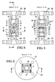
- FIG. 1-3 illustrate a flow display device according to the invention, consisting of a flow housing 4 with an essentially circular cylindrical flow chamber 3, in which an impeller 5 is rotatably mounted.
- the flow chamber 3 is equipped with an inlet channel 1 and an outlet channel 2.
- the centers of the inlet opening 7 of the inlet channel 1 of the flow chamber 3 and the outlet opening 8 of the outlet channel 2 of the flow chamber 3 are at a circumferential distance from one another which is less than 180 °.
- Inlet duct 1 and outlet duct 2 are in flow connection with housing openings 9, 10 lying on opposite end faces 12, 13 of the flow housing 4.
- the housing openings 9, 10 for inlet duct 1 and outlet duct 2 are located centrally in the opposite end faces 12, 13 of the flow housing 4. From the housing opening 9, the inlet duct 1 leads obliquely to the radial direction by means of the inlet opening 7 into the lateral surface 11 of the flow duct 3.
- the outlet channel 2 leads obliquely to the radial direction away from the outlet opening 8 from the lateral surface 11 of the flow chamber 3.
- a nozzle disk 14 equipped with an external thread is screwed, which has a nozzle bore 15 of a predetermined cross section.
- the nozzle disk 14 has two engagement openings on the outside for a turning tool.
- the central longitudinal axis 16 of the nozzle bore 15, like that of the inlet channel 1 is directed towards the radially outer end sections 17 of the vanes 6 of the impeller 5 passing the inlet opening 7.
- the blades 6 of the impeller 5 can, as indicated in Fig. 1, also be broken.
- the radially outer end sections 17 of the blades 6 of the impeller 5 keep the smallest possible distance from the lateral surface 11 of the flow chamber 3, so that the smallest possible fluid leakage takes place on the lateral surface 11.
- the impeller 5 is rotatably received on a shaft 23 which is rotatably supported in the two opposite flat side walls 22, 24 of the flow housing 4.
- the bearing for the shaft 23 is formed by a bearing element 25, 26 which is axially fixed in one side wall 22 and which is axially adjustable in the other side wall 24 from the outside.
- Both flat side walls 22, 24 of the flow housing 4 are each formed by a housing cover 17, 28 which is removably fastened by means of screws 55.
- the housing cover 27, 28 can consist of transparent material.
- the housing covers 27, 28 protrude into a recess in the side walls 22, 24 with an extension 51, 52 which receive the bearing elements 25, 26 for the shaft 23 of the impeller 5.
- There the lugs 51, 52 are radially sealed against the flow housing 4 by means of a sealing ring 53, 54.
- Inlet duct 1 and outlet duct 2 are provided with connecting sleeves 29, 30.
- the connecting sleeves 29, 30 are sealingly inserted with a sleeve section 31, 32 by means of a sealing ring 33 into a non-threaded bore of the inlet channel 1 or outlet channel 2.
- the respective sleeve section 31, 32 has a recess 34 with a round groove base, the two corresponding recesses 36, each formed by a section of two externally accessible housing bores 35, opposite the threadless bore of the inlet channel 1 and the outlet channel 2.
- a locking pin 37 designed as a threaded pin is inserted into the housing bores 35. In this way, the connecting sleeves 29, 30 are fixed axially, but rotatable relative to the flow housing 4.
- the flow display device according to FIGS. 4-6 differs from that in FIGS. 1-3 essentially only in that the connecting sleeves 29 ', 30' for inlet channel 1 and outlet channel 2 do not have an internal thread 56 for a pipe screw connection, but a flange 57, 58 for a flange connection.
- the connecting sleeves 29 ', 30' are welded to the flow housing 4 in this case.
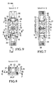
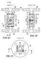
- the embodiment of the device according to FIGS. 7-9 is similar to that from FIGS. 1-3.
- the device is equipped as a flow meter, which does not only provide an optical flow indicator due to the transparent material of the one housing cover 27 offers (a housing cover 28 is missing here), but also an electrical measurement display for the flow rate or the flow.
- the impeller 5 has a number of magnets, ferrite cores or the like arranged in the circumferential distance from one another.
- the sector disk 20 forms part of the hub 21 of the impeller 5.
- the pulse-generating elements 18 are arranged directly adjacent to the flat side wall 22 of the flow housing 4, on the outside of which there is a Hall generator (not shown), a coil (not shown) or a proximity switching element (not shown) for the generation of an electrical voltage or current signal is arranged.
- a Hall generator not shown
- a coil not shown
- a proximity switching element not shown
- connection sleeves 29, 30 provided for a threaded connection are replaced by connection sleeves 29 'and 30' with flanges which with the flow housing 4 are welded, similar to the embodiment of FIGS. 4-6. Otherwise, the structure is identical.
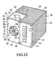
- Fig. 13 shows an oblique view of an overall device with flow housing 4, which is fitted into the recess 38 of the device housing 39 and integrated with it to form a compact overall shape.
- the connecting sleeves 29, 30 and 29 ', 30' are not shown.
- the housing cover 27 is made of transparent material, so that the device can be used both as a flow indicator and as a flow meter using the electronic circuit that is housed in the device housing 39.
- the recess 38 of the device housing 39 is cuboid-shaped in accordance with the outer shape of the flow housing 4 such that the exposed outer surfaces 40-43 of the flow housing 4 are aligned with the adjacent outer surfaces 44-47 of the device housing 39.
- the side wall 22 of the flow housing 4 is in particular flush with the frontal outer surface 44 of the device housing 39.
- the flow housing 4 is also thermally insulated from the device housing 39 in that heat-insulating plates are placed between the flow housing 4 and the device housing 39.
- the frontal outer surface 44 of the device housing 39 is equipped with an exchangeable scale field plate 50, from which the analog or digital display of the flow rate or the flow takes place, for example by means of light-emitting diodes.
- additional functions such as reaching or exceeding a predetermined limit value, the operating state (on / off) of the device, the signal range (in mA) and actuators for setting the measuring range and the like can also be displayed.
- a predetermined limit value the operating state (on / off) of the device
- the device housing 39 is designed as a section of an extruded hollow profile and its outer surfaces 40-49 are profiled, for example with ribs or grooves which run in the longitudinal direction of the extruded profile.
Landscapes
- Physics & Mathematics (AREA)
- General Physics & Mathematics (AREA)
- Fluid Mechanics (AREA)
- Electromagnetism (AREA)
- Engineering & Computer Science (AREA)
- Aviation & Aerospace Engineering (AREA)
- Measuring Volume Flow (AREA)
Applications Claiming Priority (2)
| Application Number | Priority Date | Filing Date | Title |
|---|---|---|---|
| DE19873733862 DE3733862A1 (de) | 1987-10-07 | 1987-10-07 | Stroemungsanzeige- bzw. -messgeraet |
| DE3733862 | 1987-10-07 |
Publications (2)
| Publication Number | Publication Date |
|---|---|
| EP0327671A2 true EP0327671A2 (fr) | 1989-08-16 |
| EP0327671A3 EP0327671A3 (fr) | 1991-02-27 |
Family
ID=6337786
Family Applications (1)
| Application Number | Title | Priority Date | Filing Date |
|---|---|---|---|
| EP19880114321 Withdrawn EP0327671A3 (fr) | 1987-10-07 | 1988-09-02 | Dispositif d'affichage ou de mesure d'écoulement |
Country Status (5)
| Country | Link |
|---|---|
| US (1) | US5099699A (fr) |
| EP (1) | EP0327671A3 (fr) |
| CA (1) | CA1332519C (fr) |
| DE (1) | DE3733862A1 (fr) |
| FI (1) | FI884552L (fr) |
Families Citing this family (32)
| Publication number | Priority date | Publication date | Assignee | Title |
|---|---|---|---|---|
| DE3918925A1 (de) * | 1989-06-09 | 1990-12-13 | Joseph Voegele Ag | Vorrichtung zum zuteilen von schmierstoff |
| EP0447811B1 (fr) * | 1990-03-12 | 1998-08-26 | Klaus Kobold | Dispositif d'affichage et de la mesure de débit |
| DE4028780C2 (de) * | 1990-03-12 | 1996-02-22 | Klaus Dipl Ing Kobold | Strömungsanzeige- oder Strömungsmeßgerät |
| AU2688692A (en) * | 1991-09-23 | 1993-04-27 | Futureflo System, Incorporated | Liquid flow meter |
| DE4311398C2 (de) * | 1993-04-07 | 2000-12-28 | Kobold Klaus | Flügelrad für Durchflußmesser |
| ES2180560T3 (es) * | 1994-12-20 | 2003-02-16 | Schlumberger Ind S R L | Contador de turbina para liquidos, del tipo de chorro unico con sensibilidad mejorada y efecto de regulacion. |
| TW264536B (en) * | 1995-01-13 | 1995-12-01 | Ziba Design Inc | Readily serviceable ancillary fluid filtration system having visual flow rate indicator and quick-release fluid hose fitting |
| US5876610A (en) * | 1997-03-19 | 1999-03-02 | Clack Corporation | Method and apparatus for monitoring liquid flow through an enclosed stream |
| US6149801A (en) * | 1997-08-08 | 2000-11-21 | Water Pik, Inc,. | Water treatment device with volumetric monitoring features |
| US5935426A (en) | 1997-08-08 | 1999-08-10 | Teledyne Industries, Inc., A California Corporation | Water treatment device with volumetric and time monitoring features |
| US7287398B2 (en) * | 2001-09-25 | 2007-10-30 | Alsius Corporation | Heating/cooling system for indwelling heat exchange catheter |
| DE19958640A1 (de) * | 1999-12-06 | 2001-06-07 | Brita Gmbh | Vorrichtung zur Messung von Wasserdurchflußmengen |
| EP1116938A1 (fr) * | 2000-01-11 | 2001-07-18 | Aqua S.r.l. | Filtre multifonctionel avec capteurs de pression et de débit pour circuits hydrauliques |
| USD533622S1 (en) | 2003-10-01 | 2006-12-12 | Water Pik, Inc. | End-of-faucet filter |
| US7326334B2 (en) | 2003-10-01 | 2008-02-05 | Instapure Brands, Inc. | End-of-faucet filter |
| KR100505035B1 (ko) * | 2003-11-17 | 2005-07-29 | 삼성전자주식회사 | 기판을 지지하기 위한 정전척 |
| US7305893B2 (en) * | 2005-08-11 | 2007-12-11 | The Boeing Company | Oscillating vane actuator apparatus and method for active flow control |
| US7246529B1 (en) | 2006-08-03 | 2007-07-24 | The Boeing Company | Oscillating vane actuator apparatus and method for active flow control |
| US7104143B1 (en) * | 2005-08-11 | 2006-09-12 | The Boeing Company | Oscillating vane actuator apparatus and method for active flow control |
| DE102006010374A1 (de) * | 2006-03-03 | 2007-09-06 | Mann + Hummel Gmbh | Anordnung eines Luftmassenmessers an einem Strömungskanal |
| US8069719B2 (en) * | 2009-02-11 | 2011-12-06 | Ecolab Usa Inc. | Gear flow meter with optical sensor |
| US8166828B2 (en) | 2010-08-06 | 2012-05-01 | Ecolab USA, Inc. | Fluid flow meter |
| BR112012026858A2 (pt) * | 2010-08-25 | 2018-06-05 | Carlos Jorge Gonzalez Bernal | indicador visual de fluxo de névoas formado por um corpo trapezoidal |
| RU2484246C1 (ru) * | 2011-09-30 | 2013-06-10 | Открытое акционерное общество "Российская инновационная топливно-энергетическая компания (ОАО "РИТЭК") | Способ определения дебитов и плотности пластового флюида нефтяных пластов и слоев пониженной, низкой и ультранизкой продуктивности |
| BR112014033079B1 (pt) * | 2012-07-02 | 2020-09-24 | Digmesa Ag | Fluxímetro |
| WO2015048652A1 (fr) * | 2013-09-30 | 2015-04-02 | Lincoln Industrial Corporation | Dispositif de mesure d'écoulement pour systèmes de lubrification |
| CN107036663A (zh) * | 2017-05-04 | 2017-08-11 | 安徽省锐凌计量器制造有限公司 | 一种软体叶轮流量计 |
| US10564014B2 (en) | 2017-05-30 | 2020-02-18 | Nelson Manufacturing Company | Water consumption meter |
| CN111350835A (zh) * | 2018-12-24 | 2020-06-30 | 浙江润诚智控科技有限公司 | 流量调节组件 |
| US11384958B1 (en) * | 2021-02-04 | 2022-07-12 | Tankless Technologies, Inc. | Tankless water heater with a high-accuracy response-curve flowmeter |
| CN115788919A (zh) | 2021-09-09 | 2023-03-14 | 创科无线普通合伙 | 潜水泵 |
| DE102024118263A1 (de) * | 2024-06-27 | 2025-12-31 | Endress+Hauser Flowtec Ag | Feldgerät der Prozessautomatisierung |
Family Cites Families (17)
| Publication number | Priority date | Publication date | Assignee | Title |
|---|---|---|---|---|
| DE512357C (de) * | 1930-11-21 | Siemens & Halske Akt Ges | Fluessigkeitsmesser mit einseitig beaufschlagtem Fluegelrad | |
| DE806735C (de) * | 1950-03-07 | 1951-06-18 | Helmut Janshen | Fluegelrad-Gasmengenmesser |
| DE1027892B (de) * | 1955-05-25 | 1958-04-10 | Bopp & Reuther Gmbh | Turbinenzaehler |
| US3185128A (en) * | 1963-06-06 | 1965-05-25 | Dover Corp | Sight-glass indicator or the like |
| DE1548987A1 (de) * | 1966-09-08 | 1970-08-20 | Hueckstaedt Heinz Juergen | Fluegelradzaehler |
| DE2229530B1 (de) * | 1972-06-16 | 1973-12-06 | Hydrometer Gmbh, 8800 Ansbach | Stroemungsmittelzaehler |
| CH583410A5 (fr) * | 1974-07-24 | 1976-12-31 | Aquametro Ag | |
| DE2506218B2 (de) * | 1975-02-14 | 1979-08-23 | Georg 7520 Leonberg Aigner | Einstrahl-Durchflußzähler für Flüssigkeiten |
| DE7619867U1 (de) * | 1976-06-23 | 1977-05-26 | Bopp & Reuther Gmbh, 6800 Mannheim | Durchflussmesser fuer kleine durchflussmengen |
| JPS53123965A (en) * | 1977-04-05 | 1978-10-28 | Aigner Georg | Flow meter for liquids |
| US4260637A (en) * | 1979-04-02 | 1981-04-07 | General Foods Corporation | Self-sticking bread crumb composition and process |
| DE2943184A1 (de) * | 1979-10-25 | 1981-05-07 | AOA Apparatebau Gauting GmbH, 8035 Gauting | Durchflussmesszelle |
| US4379411A (en) * | 1981-02-13 | 1983-04-12 | Interactive Design Inc. | Flow transducer |
| EP0100393B1 (fr) * | 1982-08-11 | 1988-07-27 | Kimmon Manufacturing Co., Ltd. | Débitmètre |
| FR2536852B1 (fr) * | 1982-11-26 | 1986-05-02 | Air Liquide | Compteur de gaz a alimentation tangentielle a large gamme de debit |
| US4543095A (en) * | 1983-10-14 | 1985-09-24 | E. R. Squibb & Sons, Inc. | Visual flow indicator |
| DE3608298A1 (de) * | 1986-03-13 | 1986-10-30 | Studzinski, Georg, 4040 Neuss | Durchflussmessgeraet fuer fluessigkeiten, insbesondere getraenke |
-
1987
- 1987-10-07 DE DE19873733862 patent/DE3733862A1/de not_active Withdrawn
-
1988
- 1988-09-02 EP EP19880114321 patent/EP0327671A3/fr not_active Withdrawn
- 1988-10-04 FI FI884552A patent/FI884552L/fi not_active Application Discontinuation
- 1988-10-06 CA CA000579439A patent/CA1332519C/fr not_active Expired - Fee Related
-
1990
- 1990-03-12 US US07/492,327 patent/US5099699A/en not_active Expired - Lifetime
Also Published As
| Publication number | Publication date |
|---|---|
| CA1332519C (fr) | 1994-10-18 |
| DE3733862A1 (de) | 1989-04-27 |
| FI884552A7 (fi) | 1989-04-08 |
| EP0327671A3 (fr) | 1991-02-27 |
| US5099699A (en) | 1992-03-31 |
| FI884552A0 (fi) | 1988-10-04 |
| FI884552L (fi) | 1989-04-08 |
Similar Documents
| Publication | Publication Date | Title |
|---|---|---|
| EP0327671A2 (fr) | Dispositif d'affichage ou de mesure d'écoulement | |
| DE69108935T2 (de) | Flüssigkeitsmesser mit automatischer Stromerzeugung. | |
| EP0982562B1 (fr) | Appareil de mesure de distances à câble avec matériau profilé pour boitier et tambour | |
| EP0047342B1 (fr) | Tête de mesure pour débitmètres électromagnétiques | |
| EP0671008B1 (fr) | Dispositif pour mesurer des mouvements rotatifs | |
| EP2850397B1 (fr) | Compteur sans batterie pour milieux en écoulement | |
| DE3605914A1 (de) | Magnetkupplung mit ueberwachung der drehbewegung | |
| AT508805B1 (de) | Durchflussmesseinrichtung | |
| EP1456935B1 (fr) | Moteur electrique depourvu de balais et instrument destine a un dispositif medical comprenant un moteur de ce type | |
| DE202021106468U1 (de) | Fluidvorrichtung | |
| DE102014205307A1 (de) | Stabförmiger Magnetfeldsensor | |
| EP0053575B1 (fr) | Débitmètre volumétrique à la manière d'un moteur à engrenage | |
| EP0447811A1 (fr) | Dispositif d'affichage et de la mesure de débit | |
| DE3147208A1 (de) | Volumenstromsensor nach art eines zahnradmotors | |
| EP0329040A2 (fr) | Appareil pour mesurer le volume ou le débit d'un écoulement | |
| DE9017793U1 (de) | Strömungsanzeige- bzw. -meßgerät | |
| DE2502599A1 (de) | Durchflussmesser mit einem rotor | |
| DE1623801B2 (de) | Magnetische triebkupplung fuer messgeraete, wie stroemungsmesser u.dgl. | |
| DE8715088U1 (de) | Strömungsanzeige- bzw. -meßgerät | |
| EP0009597B1 (fr) | Détecteur de contrôle du mouvement uniforme d'objets en rotation | |
| DE2759176C3 (de) | Durchflußzähler für Flüssigkeiten | |
| DE2704396C2 (de) | Vorrichtung zur Feinpositionierung einer Trägerstange für eine Sonde o.dgl. | |
| DE2508927A1 (de) | Durchflussmessgeraet | |
| EP1170575A2 (fr) | Débitmètre pour liquide,comme compteur de l' eau,et compteur de chaleur | |
| DE8103132U1 (de) | Durchflussmesser |
Legal Events
| Date | Code | Title | Description |
|---|---|---|---|
| PUAI | Public reference made under article 153(3) epc to a published international application that has entered the european phase |
Free format text: ORIGINAL CODE: 0009012 |
|
| AK | Designated contracting states |
Kind code of ref document: A2 Designated state(s): AT BE CH DE ES FR GB IT LI NL SE |
|
| PUAL | Search report despatched |
Free format text: ORIGINAL CODE: 0009013 |
|
| AK | Designated contracting states |
Kind code of ref document: A3 Designated state(s): AT BE CH DE ES FR GB IT LI NL SE |
|
| 17P | Request for examination filed |
Effective date: 19910813 |
|
| 17Q | First examination report despatched |
Effective date: 19921102 |
|
| STAA | Information on the status of an ep patent application or granted ep patent |
Free format text: STATUS: THE APPLICATION HAS BEEN WITHDRAWN |
|
| 18W | Application withdrawn |
Withdrawal date: 19930315 |