EP0327931A2 - Procédé pour l'emmagasinage et pour la transmission de données images comme fichier de données images pouvant servir à une recherche d'images - Google Patents
Procédé pour l'emmagasinage et pour la transmission de données images comme fichier de données images pouvant servir à une recherche d'images Download PDFInfo
- Publication number
- EP0327931A2 EP0327931A2 EP89101643A EP89101643A EP0327931A2 EP 0327931 A2 EP0327931 A2 EP 0327931A2 EP 89101643 A EP89101643 A EP 89101643A EP 89101643 A EP89101643 A EP 89101643A EP 0327931 A2 EP0327931 A2 EP 0327931A2
- Authority
- EP
- European Patent Office
- Prior art keywords
- image
- image data
- data
- reduced
- accordance
- Prior art date
- Legal status (The legal status is an assumption and is not a legal conclusion. Google has not performed a legal analysis and makes no representation as to the accuracy of the status listed.)
- Granted
Links
Images






Classifications
-
- G—PHYSICS
- G06—COMPUTING OR CALCULATING; COUNTING
- G06T—IMAGE DATA PROCESSING OR GENERATION, IN GENERAL
- G06T9/00—Image coding
-
- G—PHYSICS
- G06—COMPUTING OR CALCULATING; COUNTING
- G06F—ELECTRIC DIGITAL DATA PROCESSING
- G06F16/00—Information retrieval; Database structures therefor; File system structures therefor
- G06F16/50—Information retrieval; Database structures therefor; File system structures therefor of still image data
- G06F16/51—Indexing; Data structures therefor; Storage structures
Definitions
- the present invention related to a method of storing and transmitting an image data, and more particularly to an image data format suitable for image search using an image display.
- an original image data obtained by reading an original is stored or transmitted in the form of an image file in which the original image data follows a file header.
- An example of such an image file IF M is illustrated in Fig. 1 and the file header includes information for identifying the filed image.
- the original image data is often compressed through a data compression technique and then filed in the form of an image file IF N shown in Fig. 2, in order to reduce memory capacity required for storing the original image data.
- Image data requiring the data compression are classified into two types, one of which is that expressing an original image of large size and the other is that having a fine pixel pitch. For example, about 245 megabytes are required for storing a color image of A2 size under pixel pitch of 160 pixels/cm, as a total capacity for color components of yellow (Y), magenta (M), cyan (C) and black (K).
- Y yellow
- M magenta
- C cyan
- K black
- the present invention is intended for a method of storing an image file in a memory means which is provided in an image processing system having an image display usable for image search.
- the method comprises the steps of: (1) preparing a first image data expressing an original image, (2) generating a second image data expressing a reduced image of said original image, size of said reduced image being equal to or smaller than display size of said image display, (3) producing a file header including an identification data for identifying said image file, and (4) storing a combination said file header, said first image data and said second image data in said memory means as said image file.
- the reduced image is displayed on the image display for the image search. Since the size of the reduced image is equal to or smaller than the display size of the image display, the whole of the reduced image can be displayed on the image display. Consequently, the image search is easily attained as compared with the case where the original image itself is displayed.
- the storage capacity of a display buffer memory may be small, because the data amount of the reduced image is less than that of the original image. Furthermore, time and cost required for the image search is decreased, so that efficiency in the image search is improved.
- the second image data is a reduced and compressed image data obtained by compressing a reduced image data expressing the reduced image for each pixel.
- the data compression may be conducted in serial order of bit planes.
- a run-length coding rule is applied to the data compression.
- the first image data may be prepared by compressing an original image data expressing the original image for each pixel.
- the present invention may be also applied to a method of transmitting the image data.
- the image file including the combination of the file header, the first image data and the second image data is transmitted to another image processing system having an image display.
- the second image data expressing the reduced image is transmitted prior to the first image data expressing the original image.
- An operator or user can observe the reduced image on the image display in order to find whether the transmitted image file is a desired one or not.
- the second image data is that expressing the reduced image in serial order of bit planes, the gradation of the reduced image being displayed becomes fine step by step. If the operator finds that the displayed image is not a desired image, the operator inputs a cancellation command in order to stop or cancel the data transmission of the remaining part of the image file. Apparatus useful for the present method is also provided in the preferred embodiment.
- an object of the present invention is to provide a method of storing or transmitting an image file in the form suitable for image search.
- Another object of the present invention is to save a storage capacity of a display buffer memory.
- Another object of the present invention is to save time and cost required for image search or image retrieval.
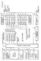
- Fig. 3 is a block diagram showing an image communication system 100 according to a preferred embodiment of the present invention.
- the system 100 comprises an image bank IB for filing an original image data therein, and an image terminal TM to which the original image data and other data are transmitted from the image bank IB through an image transmission path 40.
- the data transmitted through the path 40 are encoded data and the image terminal TM decodes the encoded data.
- a plurality of image terminals may be coupled to the image bank IM through the image transmission path 40.
- the image bank IB is placed in a data production room, while the image terminal TM is placed at a user's side.
- the image transmission path 40 may be a public telephone line, a dedicated digital communication line, an optical signal line or the like.
- the image bank IB has an image memory 4 for storing the original image data in the form of an image file, which may be a magnetic disc.
- a ROM 2 and a RAM 3 are provided in the image bank IB for storing an operation program for CPU 1 and other data.
- the image bank IB has two buffer memories 5 and 7.
- the buffer memory 5 is provided for buffering color component data of Y, M, C and K in an image filing process.
- the other buffer memory 7 is coupled to a monitor display 9 through a display controller 8, and is operable to buffer an image to be displayed.
- the monitor display 9 may be a color CRT having an arbitrary size.
- a keyboard 6 is connected to the CPU 1 for manually inputting commands and various data.
- the image terminal TM has similar structure to the image bank IB, and comprises a CPU 21, a ROM 22, a RAM 23 and an image memory 24.
- a buffer memory 25 for color components of Y, M, C and K and another buffer memory 27 for a monitor display 29 are also provided in the image terminal TM.
- the monitor display 29 may be a color CRT having an arbitrary size, and is controlled by a display controller 28.
- the function of the CPU 21 is different from that of the CPU 1 provided in the image bank IB, as will be understood later.
- the image communication system 100 operates as follows: First, an original image data expressing an original image for each scanning line is inputted to the image bank IB. An identification data for identifying an image file ot be produced is also inputted to the image bank IB. The image bank IB transforms the original image data into a reduced image of the original image. The reduced image data is subjected to data compression, whereby a reduced and compressed image data is obtained. The identification data is combined with a value expressing the size of the reduced image and another value indicating the toral amount of the reduced and compressed image data, whereby a file header FH shown in Fig. 4A and Fig. 4B is produced.
- the original image data is subjected to another data compression, to become a compressed original image data.
- the file header, the reduced and compressed image data, and the compressed original image data are stored in the image memory 4 in the form of an image file IF1 shown in Fig. 4A.
- the image file IF1 can be transmitted to the image terminal TM through the transmission path 40 to be stored in the image memory24. Search for a desired original image is also attained by displaying the reduced image on the monitor display 29.
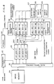
- Fig. 5 is a block diagram showing a part of the image bank IB as a combination of function blocks. Means 11 - 18 are embodied with the function of the CPU 1. Similarly, a part of the image terminal TM is illustrated in Fig. 6, where means 32 - 36 are embodied with the function of the other CPU 21.
- the original image data expressing the original image for each color component (Y, M, C and K) is inputted to the image bank IB through input means (not shown) such as a color image scanner.
- the original image data is stored in the image memory 4.
- an operator inputs the identification data through the keyboard 6, where the identification data may include an image file name, a file number, the size of the original image, a filing date, and other information useful for identifying the image file to be produced.
- a file header generating means 11 receives the identification data and then arranges the identification data to thereby generate the file header FH shown in Fig. 5B.
- the file header FH is stored in the image memory 4, where the "size of the reduced image" and the "total amount of compressed image data" shown in Fig. 5B have not been specified in the file header FH yet.
- an image reduciton means 12 determines a reduction ratio as follows; First, the respective minimum integers I X and I Y satisfying the conditions; I X ⁇ M X ⁇ L X (1) I Y ⁇ M Y ⁇ L Y (2) are calculated, where, as shown in Fig. 7A, M X , M Y : the size of the display plane 70 of the monitor display 9 or 29 in the main scanning direction X and the subscanning direction Y, the directions X and Y being defined according to image scanning for display, and L X , L Y : the size of the original image 50 in the directions X and Y.
- I M MAX [ I X , I Y ] (3)
- the integer I M is the minimum integer satisfying both of the conditions; I M ⁇ M X ⁇ L X (4) I M ⁇ M Y ⁇ L Y (5)
- the inverse of the integer I M is employed as the reduction ratio, whereby whole of the reduced image 51 (Fig. 7B) can be displayed on the side of the display plane 70 without a wide margin.
- the size of the reduced image 51 is equal to or slightly smaller than that of the display plane 70.
- the reduction ratio may be determined according to only one of the integers I X and I Y . If respective shapes of the original image 50 and the display plane 70 are squares, the reduciton ratio according to one of I X and I Y is the same with that determined through expressions (1)-(6). Even if the integers I X and I Y are different from each other, the reduciton ratio according to one of I X and I Y can be employed. This is because the reduced image is mainly used for finding a desired image within a plurality of filed images, and the reduced image may be displayed with its minor part being out of the display plane 70 in one of the directions X and Y.
- the original image data is read-out from the image memory 4 while being skipped every R pixels by a read/write control means 12 (Fig. 5) in both of the main scanning direction X and the subscanning direction Y.
- a pixel array corresponding to the original image 50 has the structure shown Fig. 8A and the reduction ration 1/R is "1/10"
- the pixels other than the pixels 61 indicated with slanted lines are skipped and the reduced image data expressing the reduced image is generated.
- Fig. 8B shows a pixel array expressing the reduced image 51, where the pixels indicated with slanted lines in Fig. 8B correspond to those illustrated in Fig. 8A.
- the reduction ratio 1/R is "1/8"
- the pixels other than the pixels 62 indicated with dots are skipped, whereby the reduced image 51 shown in Fig. 8C is generated.
- each pixel on the reduced image 51 may be obtained by taking an average of the original image data for each cluster having R2 (i.e., two or more) pixels.
- the average may be a weighted average. If the weight for the weighted average is "1" for every R-th pixels along the X(Y) direction and is "0" for other pixels, the weighted average is just the pixel skipping described above.
- the original image data is a gradation data such as the present case, the less significant bits may be deleted in the reduced image in order to further decrease the amount of data.
- the reduced image data for Y, M, C and K colors thus obtained are delivered to buffer memories 5Y-5K (Fig. 5) to be temporarily stored therein, respectively.
- the reduced image data consists of color components of Y, M, C and K, each of color components being expressed by 8 bits for each pixel.
- Fig. 9A is a schematic diagram showing a bit hierarchy of the Y-component in the reduced image, where 8 bit data B Y1 -B Y8 for each pixel are illustrated as cubic cells stacked up in the vertical direction. The cubic cells are also arrayed in the horizontal direction according to the pixel array in the reduced image.
- the lowest plane BP Y1 consisting of the most significant bits (MSB) B Y1 for respective pixels is "a first bit plane”
- the plane BP YJ consisting of J-th significant bits B YJ for respective pixels is "an J-th bit plane”.
- 9B shows the first bit plane extracted from the bit hierarchy. Since the most significant bit B Y1 through the least significant bit Y Y8 are stacked in that order, a rough level in image gradation is expressed by a lower bit plane, while a fine level is expressed by a higher bit plane in the bit hierarchy.
- the bit hierarchy formed by the bit planes can be defined also for each of other color components M, C and K.
- the most significant bits Y Y1 for respective pixels belonging to a first main scanning line L1 are read-out from the buffer memory 5Y along the pixel alignment.
- the most significant bits B Y1 are delivered in series to an encoder means 14Y, which is included in a data compression means 14 together with other encoder means 14M-14K.
- the encoder means 14Y is operable to encode the sequence of the most significant bits B Y1 into a set of run-length codes, to thereby compress the data amount of the most significant bits B Y1 in the first scanning line L1.
- the reduced and compressed image data D Y1-1 thus obtained is transmitted to the image memory 4 and is stored in an address next to the file header FH, as shown in Fig. 10, under the control with a filing control means 16.
- the similar process steps are repeated also for M, C and K colours, whereby the reduced and compressed image data D M1-1 , D C1-1 and D K1-1 for the first scanning line L1 are generated on the basis of the bit values provided in the first bit planes of respective colors.
- the reduced and compressed image data D Y1-1 through D K1-1 are stored in the image memory 4 as a part of the image file IF1 as shown in Fig. 10.
- the reduced and compressed image data thus obtained are stored in the image memory 4 as a part of the image file IF1.
- the run-length data obtained from a same bit plane are gathered to form a sub-sequence, and respective sub-sequences for the bit planes are arranged according to the bit hierarchy or in serial order of the bit planes.
- the respective run-length data for the scanning lines are aligned according to the order of the scanning lines.
- the sub-sequence for the second bit plane is located at the storage area next to that for the first bit plane
- the run-length data for the second scanning line L2 (Fig. 9B) are located in the area next to that for the first scanning line L1 in the image file IF1.
- End codes for designating the respective ends of the scanning lines and those of the sub-sequences are provided at their respective end positions in the image file IF1.
- the file header FH may consist of 512 bytes, for example.
- the original image of data of 8 bits for Y-component on the first scanning line are read-out from the image memory 4 to be delivered to the buffer memory 5Y without skipping of the pixels.
- the original image data are then transmitted to an encoder means 17Y, and compressed therein through a predictive coding rule for each scanning line. That is, an expected value of the original image data for a pixel is estimated from that of the preceding pixel, and then the deviation from the expected value is calculated to be coded into an compressed original image data D Y1 for each pixel, where the data length of the data D Y1 is variable according to the result of the data compression.
- a set of the compressed original image data D Y1 thus obtained for the first scanning line are delivered to the image memory 4, to be stored at the area next to the reduced and compressed image data in the image file IF1 (Fig. 10).
- the image file IF1 consists of the file header FH, the reduced and compressed image data, and the compressed original image data.
- Other image files for other original images can be produced through a similar process, and the image files thereof are also stored in the image memory 4.
- a user When it tis desired that on image file stored in the image memory 4 is transmitted to the image terminal TM, a user inputs the identification data for the desired image file with a keyboard 26 (Fig. 3).
- the identification data is transmitted to the image bank IB through the transmission path 40 under the control by the CPU 21.
- the CPU 1 in the image bank IB compares the transmitted identification data with those of the image files stored in the image memory 4, to thereby find an image file having the same identification data with that transmitted from the image terminal TM.
- the image file thus found is read-out from the image memory 4, and then, the file header FH, the reduced and compressed image data and the compressed original image data included therein are transmitted to the image terminal TM through the transmission path 40 in series.
- the order of the data transmission is the same with the image filing described above, and therefore, the data included in the image file are transmitted in the order shown in Fig. 10.
- the present image communication system 100 it is also possible to transmit the image file without a previous image filing. That is, when the original image data designated by the received designation data has not been arranged in the form of an image file yet, the CPU 1 starts to produce the reduced and compressed image data and the compressed original image data, and then, the produced image data are transmitted to the image terminal TM without being stored in the image memory 4.
- the transmitted image file is stored in the image memory 24 through a data receiver means (not shown), as a received image file.
- a data receiver means not shown
- the file header FH is stored in the image memory 24, while the reduced and compressed image data and the compressed original image data are stored in buffer memories 25Y-25K for each color component.
- the file header FH is read-out from the image memory 24 through a read/write control means 32.
- the respective data indicating the original image size, the reduced image size and the toral amount of the reduced and compressed image data are extracted from the file header FH, to be stored in a register (not shown).
- the read/write control means 32 read-out the YMCK components D Y1-1 - D K1-1 of the reduced and compressed image data from the image memory 24, where the components D Y1-1 - D K1-1 are those for the first scanning line in the first bit plane.
- the respective ends of the components D Y1-1 - D K1-1 can be recognized by detecting the respective end codes following them.
- the components D Y1-1 - D K1-1 are stored in the buffer memoried 25Y-25K, respectively.
- a image data reproduction means 34 comprises a set of decoding means 34Y-34K for YMCK colors, which are cyclically selected and enabled by the data reproduciton control means 33.
- the decoding means 34Y receives the data D Y1-1 for Y-component, and reproduces the reduced image data on the first scanning line in the first bit plane by decoding the run-length codes included in the data D Y1-1 .
- a reduced image data reproduced for the j-th scanning line in the i-th bit plane will be referred to as "d Fi-j ", where the index F is Y, M, C and K.
- the reduced image data first reproduced is "d Y1-1 " having one bit per pixel.
- the data d Y1-1 is delivered to the buffer memory 27, to be stored therein.
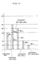
- Y color densities indicated above are schematically shown in Fig. 11 as bars indicated with the symbol "BP Y1 ".
- the process of displaying the line image on the first bit plane is repeated in series also for other colors M, C and K. More particularly, the decoder means 34M (34C, 34K) read out the data D M1-1 (D C1-1 , D K1-1 ) from the buffer memory 25M (25C, 25K) and decodes the run-length codes included therein, whereby image data d M1-1 (d C1-1 , d K1-1 ) on the first scanning line in the first bit plane are reproduced as those having one bit for each pixel.
- the data are stored in the buffer memory 27.
- the data d M1-1 (d C1-1 , d k1-1 ) are then read out with the display controller 28, and the reduced linear image for M (C, K) color is displayed on the first scanning line of the monitor display 29 together with other color component(s) being already displayed. Therefore, when all of the color components for the first scanning line in the first bit plane are reproduced, a linear full color image having a rough color gradation is obtained on the first scanning line of the monitor display 29.
- Fig. 12A is an example of the currently displayed image, which is an image having a rough color gradation as compared with the color image of 8 bits shown in Fig. 12E since only respective most significant bits for pixels are used for the display.
- the respective color densities of pixels in the composite image are expressed by the composite bars of BPY1 and BPY2 shown in Fig. 11. Since each of the composite gradation levels is expressed by the combination of the most significant bit and the second significant bit, the currently displayed image shown in Fig. 12B has a color gradation whose fineness is superior to that of the image shown in Fig. 12A.
- the above-indicated process is repeated also for the third through eighth bit planes, and the reduced image displayed on the monitor display 29 is increased step by step in its fineness of gradation, since the number of bits used for the display increases one by one from the most significant bit to the least significant bit.
- the gradation levels including the most significant bit through the third significant bit i.e., the first through third bit planes, are expressed the composite bars of BP Y1 , BP Y2 and BP Y3 as shown in Fig. 11, and the fineness are further increased as compared with the image expressed only by BP Y1 and BP Y2 .
- the user inputs a cancellation command from the keyboard 26 to cancel the request for display.
- the sequence for the decoding and the display is stopped, and no further process is conducted for the current image.
- the user inputs another identification data from the keyboard 26 in order to further try to retrieve the desired image file from the image bank IB.
- the new identification data is transmitted to the image bank IB, and the image file designated by the identification data is transmitted to the image terminal TM, and the process of decoding the run-length codes for displaying the reduced image is again carried out with respect to the transmitted new image file.
- the user finds at the display step of Fig. 12C, for example, that the reduced image being displayed is just the desired image, the user inputs a confirmation command from the keyboard 26.
- the decoding process and the display process are stopped since the displayed image is already confirmed and no further display is required for image search. If neither the cancellation command nor the confirmation command is inputted, the decoding process and the display process continue until the reduced image in the full gradation appears on the monitor display 29.
- the file header FH is accessed in order to find the information respecting the original image such as the size thereof. Then, the compressed original image data are read out in series from the image memory 24 for each scanning line and each color component, under the control by the read/write control means 32.
- the Y, M, C and K - components included in the compressed original image data are stored in the buffer memories 25Y-25K, respectively.
- a decoder means 36Y which is included in a data reproduciton means 36 together with other decorder means 36M-36K, reads out the compressed original image data D Y-1 (Fig. 10) for the first scanning line from the buffer memory 25Y, in order to decode the predictive codes included in the data D Y-1 .
- the other decorder means 36M-36K are then enabled in series, to decode the respective predictive codes of the data D M-1 , D C-1 and D K-1 , respectively, whereby reproduced original image data d M1 d C1 and d K1 for the first scanning line are obtained in time series.
- the reproduced original image data or color components d Y1 -d K1 are stored in the image memory 24 in the form where the data d Y1 -d K1 are correlated with the file header FH.
- the above-indicated process is repeated in series also for the second through last scanning lines under the control by a data reproduction control means 35, whereby a sequence of the reproduced original image data: d Y1 -d K1 , d Y2 -d K2 , ..., d YN -d KN are serially obtained and are so stored in the image memory 24 as to be correlated with the file header FH.
- the sequence of the reproduced original image data are stored at the addresses next to that for the file header FH.
- the combination of the file header FH and the reproducted original image data can be used for an arbitrary image processing such as image recoding, edition and the like. It is to be noted that the reproduced original image is not displayed on the monitor display 29 for image search, since it has been already found through the reduced image whether the image file transmitted from the image bank IB is the desired one or not.
- the desired original image is retrieved by observing the reduced image on the monitor display 29. Since the reduced image is decreased in data amount as compared with the original image, the memory capacity of the display buffer memory 27 may be relatively small. Furthermore, the whole of the reduced image can be displayed on the monitor display 29 simultaneously, and therefore, it is easily found whether the displayed image is the desired one or not.
- the reduced image can be expressed by relatively little amount of data, which is about 1.6 percents of that for the original image, for example, and the transmission thereof does not require long time. Consequently, the time and the task required for image search is decreased. Since the reduced image is dedicated to the image search, the reduciton in image quality causes no problem.
- the compression of the reduced image data being in series of the bit planes is preferred for rapid image search. Before the full gradation of the reduced image is displayed, the user can judge whether the image file being accessed is a desired one or not.
- the data compression for each scanning line is preferred for original image data expressing large original image such as that for printing process. This is because such a large original image requires a buffer memory having large storage capacity, e.g., several hundred megabytes, when it is compressed for each bit plane.
- the required capacity of the buffer memory is several hundred kilobytes, for example, in the case where the original image data is compressed for each scanning line.
- the original image data may be compressed for each bit plane, since only about one megabyte is required in the buffer memory.
- the image communication system 100 meets both of the two requirements, one of which is the rapid image search and the other is the decrease of the memory capacity and the data transmission time. Furthermore, when the reduced image is displayed prior to or in parallel with the transmission of the original image data, the transmission of the original image data can be stopped at the time when it is found that the original image is different from the desired one. This is quite effective in an image communication system using a transmission path such as a telephone line whose transmission speed is relatively low, because a relatively long time is required until whole of the original image data is transmitted.
- the image communication system 100 described above can be modified into various modes as follows;
- the reduced image included in the image file may be displayed on the monitor display 9 provided in the image bank IB.
- the program for attaining the functions shown in Fig. 6 is stored in the image bank IB as well as the image terminal TM. If the functions shown in Fig. 5 are given to both of the image terminal TM and the image bank IB, a bidirectional image communication between the image terminal TM and the image bank IB is realized, where an image transmission from the image terminal TM to the image bank IB is carried out in the process similar to that from the image bank IB to the image terminal TM.
- the image terminal TM may decode the encoded image data in parallel with the data transmission from the image bank IB, where the transmitted data are delivered to the decorder means 34Y-34K (36Y-36K) without substantial delay. If the storage capacity of the image memory 24 is relatively large, a plurality of image files may be transmitted from the image bank IB to be stored in the image memory 24. The user searches the image memory 24 for a desired image by displaying the respective reduced images in series.
- the file header, the reduced image data and the original image data may be stored and/or transmitted in a form other than the serial storage and the serial transmission, as long as these data are correlated with each other. For example, these data may be stored and/or transmitted in parallel. The correlation between these data may be indicated by adding a common reference code to each of them.
- the image data may be converted into a run-length data through data compression using Modified Huffman Coding.
- the present invention can be also applied to a monochrome image, RGB color image and other images.
- the reduced image data may be so generated as to have only the more significant bits, e.g., 4-bits, for each pixel.
- the compression of the reduced image data may be carried out for i-th bit plane while incrimenting the integer i within the range 1 ⁇ i ⁇ m, where m is an integer satisfying 1 ⁇ m ⁇ n.
- the reduced and compressed image data only for the first through m-th bit planes are stored or transmitted.
- the reduced image data may be compressed through data compression for each scanning line, e.g., the predictive coding, rather than that for each bit plane.
- data compression for the reduced image data and the original image data is preferred for further saving the memory capacity and the data transmission time, the data compression may be omitted in the image communication system 100.
- An image file IF2 has the most basic structure, and comprises a file header, a reduced image data and an original image data correlated with each other. Since it is not necessary to compress the reduced image data and the original image data, a process of producing and transmitting the image file IF2 is simplified as compared with the image file IF1 shown in Fig. 4A.
- the reduced image data and/or the original image data may be replaced by their respective compressed data in order to reduce the required memory capacity, examples of which are shown in Fig. 14 - Fig. 16 as image files IF3 - IF5.
- the reduced and compressed image data included in the image files IF3 and IF5 may be expressed in serial order of the bit planes, as embodied in image files IF 6A and IF 6B .
- image files IF 7A and IF 7B are obtained, respectively.
- the image file IF1 shown in Fig. 4A is obtained by combining the reduced and compressed image data in the image file IF 6A or IF 6B with the compressed original image data in the image file IF 7A and IF 7B .
Landscapes
- Engineering & Computer Science (AREA)
- Theoretical Computer Science (AREA)
- Physics & Mathematics (AREA)
- General Physics & Mathematics (AREA)
- Data Mining & Analysis (AREA)
- Software Systems (AREA)
- Multimedia (AREA)
- Databases & Information Systems (AREA)
- General Engineering & Computer Science (AREA)
- Storing Facsimile Image Data (AREA)
- Processing Or Creating Images (AREA)
- Editing Of Facsimile Originals (AREA)
- Information Retrieval, Db Structures And Fs Structures Therefor (AREA)
- Controls And Circuits For Display Device (AREA)
Applications Claiming Priority (2)
| Application Number | Priority Date | Filing Date | Title |
|---|---|---|---|
| JP26161/88 | 1988-02-06 | ||
| JP63026161A JPH0636182B2 (ja) | 1988-02-06 | 1988-02-06 | 画像ファイリング・検索方法および装置 |
Publications (3)
| Publication Number | Publication Date |
|---|---|
| EP0327931A2 true EP0327931A2 (fr) | 1989-08-16 |
| EP0327931A3 EP0327931A3 (fr) | 1991-10-16 |
| EP0327931B1 EP0327931B1 (fr) | 1994-10-05 |
Family
ID=12185831
Family Applications (1)
| Application Number | Title | Priority Date | Filing Date |
|---|---|---|---|
| EP89101643A Expired - Lifetime EP0327931B1 (fr) | 1988-02-06 | 1989-01-31 | Procédé pour l'emmagasinage et pour la transmission de données images comme fichier de données images pouvant servir à une recherche d'images |
Country Status (4)
| Country | Link |
|---|---|
| US (1) | US4992887A (fr) |
| EP (1) | EP0327931B1 (fr) |
| JP (1) | JPH0636182B2 (fr) |
| DE (1) | DE68918605T2 (fr) |
Cited By (22)
| Publication number | Priority date | Publication date | Assignee | Title |
|---|---|---|---|---|
| WO1992005504A1 (fr) * | 1990-09-14 | 1992-04-02 | Eastman Kodak Company | Base de donnees d'images comprenant des donnees d'images de repertoire a faible resolution |
| EP0435174A3 (en) * | 1989-12-25 | 1992-04-15 | Kabushiki Kaisha Toshiba | Image forming/storing apparatus which can store image data and can efficiently perform document filing |
| WO1992005652A3 (fr) * | 1990-09-19 | 1992-04-30 | Koninkl Philips Electronics Nv | Mecanisme servant a commander la presentation d'images affichees |
| EP0435169A3 (en) * | 1989-12-26 | 1992-06-10 | Hitachi Naka Seiki, Ltd. | Image display system and method of displaying an image therewith |
| EP0551990A1 (fr) * | 1992-01-14 | 1993-07-21 | International Business Machines Corporation | Procédé et appareil de compression de signaux vidéo numériques |
| WO1993018467A1 (fr) * | 1992-03-04 | 1993-09-16 | Eden Group Limited | Procede et appareil de mise en memoire et de visualisation de documents |
| EP0599466A1 (fr) * | 1992-10-07 | 1994-06-01 | Sony Corporation | Procédé et dispositif pour la gestion de données d'images |
| GB2274224A (en) * | 1993-01-07 | 1994-07-13 | Sony Broadcast & Communication | Image data compression |
| EP0613303A3 (fr) * | 1993-01-18 | 1995-02-22 | Matsushita Electric Industrial Co Ltd | Appareil et méthode de compression de signal d'image. |
| EP0649254A1 (fr) * | 1993-10-14 | 1995-04-19 | Koninklijke Philips Electronics N.V. | Méthode de stockage de données d'images codées |
| BE1007658A3 (nl) * | 1993-10-14 | 1995-09-05 | Philips Electronics Nv | Werkwijze voor het in gecodeerde vorm opslaan van beeldinformatie van bewegende beelden, een diagnostisch systeem waarin de werkwijze wordt toegepast, alsmede een beeldcoderings- en optekeneenheid voor toepassing in een dergelijk systeem. |
| WO1995026108A1 (fr) * | 1994-03-23 | 1995-09-28 | British Telecommunications Public Limited Company | Codage de signaux video |
| EP0684565A1 (fr) * | 1994-05-27 | 1995-11-29 | Eastman Kodak Company | Archivage d'images médicales, images avec et sans pertes d'informations, sur un CD enregistrable |
| EP0698874A1 (fr) * | 1994-07-25 | 1996-02-28 | Texas Instruments Incorporated | Méthode pour réduire l'artefact temporel dans des systèmes vidéo numériques |
| EP0766183A1 (fr) * | 1995-09-29 | 1997-04-02 | Hewlett-Packard Company | Regarder des informations stockées électroniquement |
| EP0502173B1 (fr) * | 1990-09-14 | 1997-04-16 | Eastman Kodak Company | Mecanisme commandant la presentation d'une image affichee |
| WO1998037700A1 (fr) * | 1997-02-19 | 1998-08-27 | Btg International Limited | Codage progressif par bloc pour la compression d'images |
| EP0758178B1 (fr) * | 1995-02-28 | 2002-08-28 | Sony Corporation | Dispositif d'impression de donnees d'image et dispositif permettant de produire des donnees d'image |
| EP1083493A3 (fr) * | 1999-09-09 | 2003-01-22 | Heimann Systems GmbH | Méthode pur la gestion d'images radiographiques |
| EP1026889A3 (fr) * | 1999-01-27 | 2003-08-06 | General Instrument Corporation | Optimisation de largeur de bande passante de DRAM synchrone pour réduire la taille d'affichage d'une image MPEG-2 |
| EP0987637A3 (fr) * | 1998-08-31 | 2004-03-17 | Canon Kabushiki Kaisha | Appareil et méthode pour stocker des images |
| US6825854B1 (en) | 1999-09-09 | 2004-11-30 | Heimann Systems Gmbh | Method for image management of X-ray images |
Families Citing this family (38)
| Publication number | Priority date | Publication date | Assignee | Title |
|---|---|---|---|---|
| JPH02195480A (ja) * | 1989-01-25 | 1990-08-02 | Hitachi Ltd | 画像データの検索方式 |
| JP3265429B2 (ja) * | 1990-09-14 | 2002-03-11 | キヤノン株式会社 | カラーファクシミリ装置 |
| US5488486A (en) * | 1991-03-11 | 1996-01-30 | Ricoh Company, Ltd. | Image processing system |
| JPH0644320A (ja) * | 1991-05-14 | 1994-02-18 | Sony Corp | 情報検索システム |
| US5349348A (en) * | 1991-08-15 | 1994-09-20 | International Business Machines Corporation | Multi-mode data stream generator |
| GB2262365B (en) * | 1991-12-10 | 1995-08-09 | Sony Broadcast & Communication | Apparatus and methods for designing,analyzing or simulating signal processing functions |
| JPH0728689A (ja) | 1993-07-09 | 1995-01-31 | Hitachi Ltd | 情報処理装置 |
| KR0151234B1 (ko) * | 1993-06-03 | 1998-10-15 | 모리시타 요이찌 | 화상재생장치 및 화상복호장치 |
| JP3556265B2 (ja) * | 1994-03-04 | 2004-08-18 | オリンパス株式会社 | 画像取扱装置及びカメラ |
| JPH07245700A (ja) * | 1994-03-04 | 1995-09-19 | Minolta Co Ltd | デジタル複写機 |
| US5506691A (en) * | 1994-03-23 | 1996-04-09 | International Business Machines Corporation | Method and apparatus for image processing at remote sites |
| US6005679A (en) * | 1994-08-22 | 1999-12-21 | Fuji Photo Film Co., Ltd. | Image data filing system for quickly retrieving an area of interest of an image from a reduced amount of image data |
| US5861887A (en) * | 1995-12-05 | 1999-01-19 | Electronic Data Systems Corporation | Graphic image compression and storage system |
| JPH10150523A (ja) * | 1996-11-20 | 1998-06-02 | Fuji Photo Film Co Ltd | デジタルカメラにより撮影された写真画像データの保管活用システム |
| US5973734A (en) | 1997-07-09 | 1999-10-26 | Flashpoint Technology, Inc. | Method and apparatus for correcting aspect ratio in a camera graphical user interface |
| JP3028096B2 (ja) * | 1998-03-09 | 2000-04-04 | 日本電気株式会社 | 画像データ転送システムおよび方法 |
| US6317141B1 (en) | 1998-12-31 | 2001-11-13 | Flashpoint Technology, Inc. | Method and apparatus for editing heterogeneous media objects in a digital imaging device |
| JP4144961B2 (ja) * | 1999-01-14 | 2008-09-03 | 富士フイルム株式会社 | 画像データ通信システム,サーバ・システムおよびその制御方法ならびにサーバ・システムを制御するためのプログラムを格納した記録媒体 |
| US7369161B2 (en) * | 1999-06-08 | 2008-05-06 | Lightsurf Technologies, Inc. | Digital camera device providing improved methodology for rapidly taking successive pictures |
| US8212893B2 (en) * | 1999-06-08 | 2012-07-03 | Verisign, Inc. | Digital camera device and methodology for distributed processing and wireless transmission of digital images |
| US7372485B1 (en) * | 1999-06-08 | 2008-05-13 | Lightsurf Technologies, Inc. | Digital camera device and methodology for distributed processing and wireless transmission of digital images |
| US7103357B2 (en) * | 1999-11-05 | 2006-09-05 | Lightsurf Technologies, Inc. | Media spooler system and methodology providing efficient transmission of media content from wireless devices |
| US7847833B2 (en) * | 2001-02-07 | 2010-12-07 | Verisign, Inc. | Digital camera device providing improved methodology for rapidly taking successive pictures |
| US7664296B2 (en) * | 2001-01-31 | 2010-02-16 | Fujifilm Corporation | Image recording method and system, image transmitting method, and image recording apparatus |
| JP2002281289A (ja) * | 2001-03-15 | 2002-09-27 | Konica Corp | 医用画像生成装置、医用画像処理装置及び医用ネットワークシステム |
| US7305354B2 (en) | 2001-03-20 | 2007-12-04 | Lightsurf,Technologies, Inc. | Media asset management system |
| US7724281B2 (en) | 2002-02-04 | 2010-05-25 | Syniverse Icx Corporation | Device facilitating efficient transfer of digital content from media capture device |
| US7051040B2 (en) * | 2002-07-23 | 2006-05-23 | Lightsurf Technologies, Inc. | Imaging system providing dynamic viewport layering |
| US7653244B2 (en) * | 2005-02-22 | 2010-01-26 | Potts Wesley F | Intelligent importation of information from foreign applications user interface |
| JP2008042401A (ja) * | 2006-08-03 | 2008-02-21 | Canon Inc | 情報処理装置、情報処理方法 |
| US20080052026A1 (en) * | 2006-08-23 | 2008-02-28 | Qurio Holdings, Inc. | Configuring a content capture device for one or more service providers |
| US9224145B1 (en) | 2006-08-30 | 2015-12-29 | Qurio Holdings, Inc. | Venue based digital rights using capture device with digital watermarking capability |
| WO2008087914A1 (fr) | 2007-01-15 | 2008-07-24 | Panasonic Corporation | Dispositif d'imagerie |
| KR100889026B1 (ko) * | 2008-07-22 | 2009-03-17 | 김정태 | 이미지를 이용한 검색 시스템 |
| US8160392B1 (en) * | 2008-10-01 | 2012-04-17 | Adobe Systems Incorporated | Automatic suggestion of image blending techniques |
| JP5495879B2 (ja) * | 2009-04-30 | 2014-05-21 | キヤノン株式会社 | 画像処理システム |
| JP2014127188A (ja) * | 2012-12-27 | 2014-07-07 | Toshiba Corp | 整形装置及び方法 |
| CN103092991B (zh) * | 2013-02-08 | 2016-09-07 | 宁波江丰生物信息技术有限公司 | 图像的信息处理方法及装置、显示方法及装置 |
Family Cites Families (12)
| Publication number | Priority date | Publication date | Assignee | Title |
|---|---|---|---|---|
| US3377423A (en) * | 1963-02-11 | 1968-04-09 | Army Usa | Reduced bandwidth binary picture transmission |
| JPS5779578A (en) * | 1980-11-05 | 1982-05-18 | Toshiba Corp | Retrieval device for picture information storage |
| US4520399A (en) * | 1982-01-29 | 1985-05-28 | Tokyo Shibaura Kenki Kabushiki Kaisha | Picture information display device |
| JPS6047564A (ja) * | 1983-08-26 | 1985-03-14 | Toshiba Corp | 画像情報記憶検索装置 |
| JPS6068475A (ja) * | 1983-09-24 | 1985-04-19 | Toshiba Corp | 階層的配列デ−タ記憶方式 |
| JPS6089241A (ja) * | 1983-10-20 | 1985-05-20 | Fujitsu Ltd | ドキユメントフアイル装置 |
| JPH0679334B2 (ja) * | 1985-07-18 | 1994-10-05 | 株式会社日立メデイコ | デ−タ圧縮方法 |
| US4672444A (en) * | 1985-11-14 | 1987-06-09 | Rca Corporation | Method for transmitting a high-resolution image over a narrow-band communication channel |
| US4829453A (en) * | 1987-03-05 | 1989-05-09 | Sharp Kabushiki Kaisha | Apparatus for cataloging and retrieving image data |
| JPS634375A (ja) * | 1986-06-25 | 1988-01-09 | Toshiba Corp | 画像圧縮装置 |
| JPS636672A (ja) * | 1986-06-27 | 1988-01-12 | Fuji Photo Film Co Ltd | 医用画像蓄積再生方法 |
| US4764805A (en) * | 1987-06-02 | 1988-08-16 | Eastman Kodak Company | Image transmission system with line averaging preview mode using two-pass block-edge interpolation |
-
1988
- 1988-02-06 JP JP63026161A patent/JPH0636182B2/ja not_active Expired - Lifetime
-
1989
- 1989-01-31 EP EP89101643A patent/EP0327931B1/fr not_active Expired - Lifetime
- 1989-01-31 DE DE68918605T patent/DE68918605T2/de not_active Expired - Fee Related
- 1989-02-03 US US07/306,573 patent/US4992887A/en not_active Expired - Fee Related
Cited By (33)
| Publication number | Priority date | Publication date | Assignee | Title |
|---|---|---|---|---|
| EP0435174A3 (en) * | 1989-12-25 | 1992-04-15 | Kabushiki Kaisha Toshiba | Image forming/storing apparatus which can store image data and can efficiently perform document filing |
| EP0435169A3 (en) * | 1989-12-26 | 1992-06-10 | Hitachi Naka Seiki, Ltd. | Image display system and method of displaying an image therewith |
| EP0502173B1 (fr) * | 1990-09-14 | 1997-04-16 | Eastman Kodak Company | Mecanisme commandant la presentation d'une image affichee |
| WO1992005504A1 (fr) * | 1990-09-14 | 1992-04-02 | Eastman Kodak Company | Base de donnees d'images comprenant des donnees d'images de repertoire a faible resolution |
| WO1992005652A3 (fr) * | 1990-09-19 | 1992-04-30 | Koninkl Philips Electronics Nv | Mecanisme servant a commander la presentation d'images affichees |
| US5633726A (en) * | 1990-09-19 | 1997-05-27 | U.S. Philips Corporation | Digitized picture display system with added control files |
| EP0551990A1 (fr) * | 1992-01-14 | 1993-07-21 | International Business Machines Corporation | Procédé et appareil de compression de signaux vidéo numériques |
| WO1993018467A1 (fr) * | 1992-03-04 | 1993-09-16 | Eden Group Limited | Procede et appareil de mise en memoire et de visualisation de documents |
| US6081251A (en) * | 1992-10-07 | 2000-06-27 | Sony Corporation | Apparatus and method for managing picture data |
| EP0599466A1 (fr) * | 1992-10-07 | 1994-06-01 | Sony Corporation | Procédé et dispositif pour la gestion de données d'images |
| GB2274224B (en) * | 1993-01-07 | 1997-02-26 | Sony Broadcast & Communication | Data compression |
| GB2274224A (en) * | 1993-01-07 | 1994-07-13 | Sony Broadcast & Communication | Image data compression |
| US6243496B1 (en) | 1993-01-07 | 2001-06-05 | Sony United Kingdom Limited | Data compression |
| US5440404A (en) * | 1993-01-18 | 1995-08-08 | Matsushita Electric Industrial Co., Ltd. | Image signal compression apparatus and method using variable length encoding |
| EP0613303A3 (fr) * | 1993-01-18 | 1995-02-22 | Matsushita Electric Industrial Co Ltd | Appareil et méthode de compression de signal d'image. |
| BE1007658A3 (nl) * | 1993-10-14 | 1995-09-05 | Philips Electronics Nv | Werkwijze voor het in gecodeerde vorm opslaan van beeldinformatie van bewegende beelden, een diagnostisch systeem waarin de werkwijze wordt toegepast, alsmede een beeldcoderings- en optekeneenheid voor toepassing in een dergelijk systeem. |
| EP0649254A1 (fr) * | 1993-10-14 | 1995-04-19 | Koninklijke Philips Electronics N.V. | Méthode de stockage de données d'images codées |
| WO1995026108A1 (fr) * | 1994-03-23 | 1995-09-28 | British Telecommunications Public Limited Company | Codage de signaux video |
| US5864646A (en) * | 1994-03-23 | 1999-01-26 | British Telecommunications Public Limited Company | Video signal coding of plural related frame sequences for selective replay |
| EP0684565A1 (fr) * | 1994-05-27 | 1995-11-29 | Eastman Kodak Company | Archivage d'images médicales, images avec et sans pertes d'informations, sur un CD enregistrable |
| EP0698874A1 (fr) * | 1994-07-25 | 1996-02-28 | Texas Instruments Incorporated | Méthode pour réduire l'artefact temporel dans des systèmes vidéo numériques |
| EP0758178B1 (fr) * | 1995-02-28 | 2002-08-28 | Sony Corporation | Dispositif d'impression de donnees d'image et dispositif permettant de produire des donnees d'image |
| US6281986B1 (en) | 1995-09-29 | 2001-08-28 | Hewlett-Packard Company | Method for browsing electronically stored information |
| EP0766183A1 (fr) * | 1995-09-29 | 1997-04-02 | Hewlett-Packard Company | Regarder des informations stockées électroniquement |
| WO1998037700A1 (fr) * | 1997-02-19 | 1998-08-27 | Btg International Limited | Codage progressif par bloc pour la compression d'images |
| US6556719B1 (en) | 1997-02-19 | 2003-04-29 | University Of Bath | Progressive block-based coding for image compression |
| USRE43649E1 (en) | 1997-02-19 | 2012-09-11 | Ayscough Visuals Llc | Progressive block-based coding for image compression |
| EP0987637A3 (fr) * | 1998-08-31 | 2004-03-17 | Canon Kabushiki Kaisha | Appareil et méthode pour stocker des images |
| US6813394B1 (en) | 1998-08-31 | 2004-11-02 | Canon Kabushiki Kaisha | Image storage method and apparatus |
| EP1026889A3 (fr) * | 1999-01-27 | 2003-08-06 | General Instrument Corporation | Optimisation de largeur de bande passante de DRAM synchrone pour réduire la taille d'affichage d'une image MPEG-2 |
| EP1083493A3 (fr) * | 1999-09-09 | 2003-01-22 | Heimann Systems GmbH | Méthode pur la gestion d'images radiographiques |
| US6825854B1 (en) | 1999-09-09 | 2004-11-30 | Heimann Systems Gmbh | Method for image management of X-ray images |
| RU2268487C2 (ru) * | 1999-09-09 | 2006-01-20 | Хайманн Системс Гмбх | Способ управления видеоданными рентгеновских изображений |
Also Published As
| Publication number | Publication date |
|---|---|
| JPH01201776A (ja) | 1989-08-14 |
| DE68918605D1 (de) | 1994-11-10 |
| JPH0636182B2 (ja) | 1994-05-11 |
| DE68918605T2 (de) | 1995-01-26 |
| EP0327931B1 (fr) | 1994-10-05 |
| EP0327931A3 (fr) | 1991-10-16 |
| US4992887A (en) | 1991-02-12 |
Similar Documents
| Publication | Publication Date | Title |
|---|---|---|
| EP0327931B1 (fr) | Procédé pour l'emmagasinage et pour la transmission de données images comme fichier de données images pouvant servir à une recherche d'images | |
| CA1240789A (fr) | Systeme de traitement d'images | |
| JP4490261B2 (ja) | イントラ符号化に基づく空間予測 | |
| Sneyers et al. | FLIF: Free lossless image format based on MANIAC compression | |
| JP2621747B2 (ja) | 画像処理装置 | |
| US20040008771A1 (en) | Spatial prediction based intra coding | |
| JP2003520531A (ja) | イメージをコード化する方法およびイメージコーダ | |
| EP0776569B1 (fr) | Procede et systeme de codage/decodage de donnees d'images | |
| EP1084568A1 (fr) | Compression d'images | |
| US8189687B2 (en) | Data embedding apparatus, data extracting apparatus, data embedding method, and data extracting method | |
| US5335088A (en) | Apparatus and method for encoding halftone images | |
| AU686356B2 (en) | Lossy compression land expansion algorithm for image representative data | |
| EP1009167A2 (fr) | Procédé et dispositif de compression électronique de données | |
| US6339659B1 (en) | Fractal coding/decoding of picture data using memory capacity information | |
| JP2001078049A (ja) | 画像処理装置および画像処理方法 | |
| KR100495001B1 (ko) | 이미지 압축 부호화 방법 및 시스템 | |
| Mounts et al. | An ordering scheme for facsimile coding | |
| JP2001268369A (ja) | 画像データ符号化装置、画像データ符号化方法、記録媒体及び画像形成装置 | |
| JP3263218B2 (ja) | 画情報データ圧縮再生装置 | |
| JP3736107B2 (ja) | 画像処理装置 | |
| JP3295507B2 (ja) | 二値画像符号化復号化方法 | |
| JPH0435361A (ja) | 画像符号化装置および画像符号化・複合化装置 | |
| JP2001197317A (ja) | 画像データ符号化装置、画像データ符号化方法、記録媒体及び画像形成装置 | |
| JPH0750828A (ja) | 画像符号化装置 | |
| JPS6358425B2 (fr) |
Legal Events
| Date | Code | Title | Description |
|---|---|---|---|
| PUAI | Public reference made under article 153(3) epc to a published international application that has entered the european phase |
Free format text: ORIGINAL CODE: 0009012 |
|
| AK | Designated contracting states |
Kind code of ref document: A2 Designated state(s): DE FR GB |
|
| PUAL | Search report despatched |
Free format text: ORIGINAL CODE: 0009013 |
|
| AK | Designated contracting states |
Kind code of ref document: A3 Designated state(s): DE FR GB |
|
| 17P | Request for examination filed |
Effective date: 19920302 |
|
| 17Q | First examination report despatched |
Effective date: 19930721 |
|
| GRAA | (expected) grant |
Free format text: ORIGINAL CODE: 0009210 |
|
| AK | Designated contracting states |
Kind code of ref document: B1 Designated state(s): DE FR GB |
|
| PG25 | Lapsed in a contracting state [announced via postgrant information from national office to epo] |
Ref country code: FR Effective date: 19941005 |
|
| REF | Corresponds to: |
Ref document number: 68918605 Country of ref document: DE Date of ref document: 19941110 |
|
| EN | Fr: translation not filed | ||
| PLBE | No opposition filed within time limit |
Free format text: ORIGINAL CODE: 0009261 |
|
| STAA | Information on the status of an ep patent application or granted ep patent |
Free format text: STATUS: NO OPPOSITION FILED WITHIN TIME LIMIT |
|
| 26N | No opposition filed | ||
| PGFP | Annual fee paid to national office [announced via postgrant information from national office to epo] |
Ref country code: GB Payment date: 19980122 Year of fee payment: 10 |
|
| PGFP | Annual fee paid to national office [announced via postgrant information from national office to epo] |
Ref country code: DE Payment date: 19980206 Year of fee payment: 10 |
|
| PG25 | Lapsed in a contracting state [announced via postgrant information from national office to epo] |
Ref country code: GB Free format text: LAPSE BECAUSE OF NON-PAYMENT OF DUE FEES Effective date: 19990131 |
|
| GBPC | Gb: european patent ceased through non-payment of renewal fee |
Effective date: 19990131 |
|
| PG25 | Lapsed in a contracting state [announced via postgrant information from national office to epo] |
Ref country code: DE Free format text: LAPSE BECAUSE OF NON-PAYMENT OF DUE FEES Effective date: 19991103 |