EP0328976A1 - Dispositif de sélection d'aiguilles pour un métier à tricoter - Google Patents
Dispositif de sélection d'aiguilles pour un métier à tricoter Download PDFInfo
- Publication number
- EP0328976A1 EP0328976A1 EP89101977A EP89101977A EP0328976A1 EP 0328976 A1 EP0328976 A1 EP 0328976A1 EP 89101977 A EP89101977 A EP 89101977A EP 89101977 A EP89101977 A EP 89101977A EP 0328976 A1 EP0328976 A1 EP 0328976A1
- Authority
- EP
- European Patent Office
- Prior art keywords
- selection
- needle cylinder
- heel
- selection lever
- lever
- Prior art date
- Legal status (The legal status is an assumption and is not a legal conclusion. Google has not performed a legal analysis and makes no representation as to the accuracy of the status listed.)
- Granted
Links
Images


Classifications
-
- D—TEXTILES; PAPER
- D04—BRAIDING; LACE-MAKING; KNITTING; TRIMMINGS; NON-WOVEN FABRICS
- D04B—KNITTING
- D04B15/00—Details of, or auxiliary devices incorporated in, weft knitting machines, restricted to machines of this kind
- D04B15/66—Devices for determining or controlling patterns ; Program-control arrangements
- D04B15/68—Devices for determining or controlling patterns ; Program-control arrangements characterised by the knitting instruments used
- D04B15/78—Electrical devices
Definitions
- the present invention relates to a needle selection device for circular knitting machines.
- circular knitting machines comprise a needle cylinder with a skirt in which a plurality of grooves is defined; said grooves extend parallel to the axis of said skirt, and each accommodates a needle and a selector or sub-needle.
- the needles are actuated with an alternating motion along their related grooves by means of cams, arranged around the needle cylinder which engage with a needle heel protruding radially from the grooves, and which, upon rotation of the needle cylinder about its own axis relatively to said cams, cause this alternating motion.
- selection devices which act on the selectors so as to engage or prevent the engagement of a main heel thereof with a lifting cam which, if it engages said main heel, moves the selector to act on the overlying needle to engage its heel in a preset path defined by the related cams for causing it to knit.
- Selectors generally have, below their main heel, one or more selection heels located at different heights.
- the selectors are accommodated in the related grooves of the needle cylinder and can oscillate in a radial plane towards or away from the axis of the needle cylinder so as to pass from an inoperative position, in which their main heel is completely inserted into the related groove of the needle cylinder and therefore does not engage with the lifting cam when the overlying needle is to be excluded from knitting, to an operative position, in which their main heel portrudes radially from the related groove to engage with the lifting cam when the overlying needle must knit.
- selection devices In order to oscillate the selectors and therefore move them from their operative position to their inoperative position or vice versa, selection devices are generally used which comprise a plurality of selection levers arranged upstream of the lifting cam, according to the direction of rotation of the needle cylinder.
- Each selection lever has one of its ends directed towards the needle cylinder and arranged substantially at the level of one of the selection heels of the selectors, and can be controllably moved from a first position, in which it interferes with one or more selection heels to oscillate the related selectors, to a second position in which it does not interfere with the selection heels of the selectors.
- the selection levers are moved from the first position to the second and vice versa by oscillating the selection levers or by moving the selection levers towards or away from the axis of the needle cylinder. In some selection devices this movement is achieved by mechanical actuation means, while in other it is achieved by electromagnets which are energized or de-energized according to the knitting program of the machine.
- the aim of the present invention is to obviate the disadvantages described above by providing a needle selection device for circular knitting machines which allows a wide possibility of selection with reduced-length selectors while their longitudinal flexing is safely avoided.
- an object of the invention is to provide a device which can be actuated with reduced-power electromagnets, avoiding overheating problems.
- Another object of the invention is to propose a device which is simple to produce with commonly available materials and requires reduced maintenance interventions.
- a needle selection device for circular knitting machines, comprising a plurality of selectors accommodated in grooves defined in the skirt of the needle cylinder and extending parallel to the axis of said needle cylinder, each of said selectors being arranged below a needle and being controllably movable along its related groove by virtue of the action of at least one lifting cam which is arranged laterally facing the needle cylinder and is engageable, upon rotation of said needle cylinder about its axis relatively to said lifting cam, with a heel of said selectors protruding radially from a related groove, said device further comprising actuation means acting on said selectors to move them from an inoperative position, in which said heel of said selectors does not interfere with said lifting cam, to an operative position, in which said selector heel engages with said lifting cam, and vice versa, characterized in that said actuation means comprise a selection element which is accommodated below a selector in the related groove of
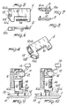
- the first aspect of the device according to the invention comprises a plurality of selectors 2 or sub-needles, slidably accommodated in grooves 3 defined in the skirt of the needle cylinder 4 parallel to its axis.
- Each selector 2 is arranged below a needle 5 accommodated in the same groove and is oscillable in a plane which is radial with respect to the needle cylinder from an inoperative position, in which a heel 2a of said selector is inserted into the related groove 3, to an operative position, in which said heel 2a protrudes from the related groove 3.
- Lifting cams 6 are arranged around the needle cylinder, and the heel 2a of the selectors engages with said cams in the operative position when the needle cylinder rotates about its axis relatively to the lifting cams 6.
- a selection element 7 is accommodated below each selector in the grooves 3 of the needle cylinder and is constituted by a stem 7a with one or more heels 7b which protrude radially from their related groove.
- At least one selection lever 8 is provided laterally of the needle cylinder 4 and one of its ends is arranged facing the heel 7b of the selection element 7; said selection lever is controllably movable from a first position, in which said end interferes with the heel 7b, to a second position, in which it does not interfere with the heel 7b.
- a frame 9 is fixed relatively to the lifting cams 6 and supports a plurality of selection levers 8 so that they are slidable in a radial direction with respect to the needle cylinder; said selection levers overlap one another and their ends directed towards the needle cylinder are at different heights so that each end is at the level of one of the heels 7b of the selectors.
- Each selection lever is constituted by a flat lamina 10; the end of said lever directed towards the needle cylinder defines a rising portion 10a which extends on an inclined plane with respect to the axis of the needle cylinder.
- the heel 7b of the selection element engages with said rising portion 10a when the selection lever is in the first position.
- said end of the selection lever has, upstream of the rising portion according to the direction of rotation of the needle cylinder, a first portion 10b which is contacted by the heels 7b of the selection elements arranged at this level so as to move the selection lever from the first position to the second; retention means 11 are provided, which are controllably activatable or deactivatable so as to retain, or not retain, the selection lever in this position.
- each selection lever 8 can move from the first position to the second position along a radial direction with respect to the needle cylinder, and said retention means 11 are constituted by an electromagnet 12 which is connected to an electronic machine control element 13 and is arranged facing the end of the selection lever, made of ferromagnetic material, which is opposite with respect to the needle cylinder.
- Said control element 13 activates the electromagnet 12 or does not activate it according to a preset knitting program.
- the movement of the selection lever from the first position to the second position is biased by elastic return means, constituted for example by a spring 14, having one end associated with a selection lever, and another end associated with the frame 9.
- the first portion 10b conveniently has a rounded guiding portion 10c which is inclined with respect to a radial plane of the needle cylinder and parallel to the axis of said needle cylinder.
- the first portion 10b portrudes with respect to the rising portion 10a towards the needle cylinder.
- a recess or missing portion 15 is furthermore defined between said rising portion and the first portion 10b.
- each selection element In order to move the selectors 2 from their inoperative position to the operative positon, the upper end 7c of each selection element is shaped according to a plane which is inclined with respect to the axis of the needle cylinder, and engages with the lower end of the overlying selector, said end also being shaped according to an inclined plane, so that the lifting of the selection element causes oscillation of the overlying selector, thereby extracting its heel 2a from the related groove.
- Cams are arranged around the needle cylinder and actuate the needles 5, which have a heel 5a, as well as the selectors 2 and the selection elements 7.
- the aspect of the invention illustrated merely by way of example in figure 3 features a selection element cam 17 in which a recess or missing portion 18 is defined at the selection levers 8. Said recess 18 allows the selection elements 8 to rise and lowers them by means of a decending portion 18a, wherewith engages an auxiliary heel 7b of the selection elements which may be lifted by the selection levers.
- the lifting cam 6 is arranged at the heel 2a of the selectors and has a rising portion 6a immediately downstream of the selection levers according to the direction of rotation of the needle cylinder, indicated by an arrow 19.
- Each selector has a second heel 2c which always protrudes from its related groove and engages a cam 20 having a rising portion 20a spaced downstream of the rising portion 6a of the cam 6.
- a countercam 21 is arranged between the cam 6 and the cam 20.
- a cam 22 is arranged at the level of the heels 5a of the needles 5 and has a descending portion 22a downstream of the rising portion 20a of the cam 20.
- Figure 3 illustrates the paths of the heels 5a, 2a, 2c, 7b and 7d of the various elements in a groove 3; respectively, the vertical lines indicate the path 23 followed by the heels when the selection lever 8 corresponding to the heel of the selection element being considered is in the first position, and the dots indicate the path 24 followed by the heels when the selection lever 8 is retained in the second position, as will become apparent hereinafter.
- the electromagnet 12 When the needle 5 arranged in a preset groove 3 is to be moved into an operative or knitting position, after the heel 7b of the underlying selection element 7 has pushed the corresponding selection lever 8 to its second position by following the first portion 10b, the electromagnet 12 is not activated and the selection lever 8 therefore returns to its first position due to the action of the spring 14. The heel 7b then passes in the recess 15 and engages with the rising portion 10a. The selection element 7 is thus raised and moves the overlying selector 2 to its operative position by acting on it. In this manner, the heel 2a engages with the rising portion 6a and raises the needle 5, causing it to knit.
- the selection element 7, the selector 2 and the needle 5 are subsequently lowered by the descending portions 18a, 20a and 22a, and the heels 2a of the selector 2 is inserted into its related groove by a known pusher element 48 arranged upstream the lifting cam 6.
- the electromagnet 12 which has been energized, retains the related selection lever 8. In this manner, the selection element does not engage the rising portion 10a and the selector 2 is kept in an inoperative position.
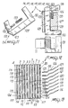
- Figures 11 to 25 illustrates a second aspect of the selection device according to the invention, which is generally indicated by the reference numeral 101. This is preferred for machines with a large number of needles per unit of length and high operating speeds.
- cams are arranged around the needle cylinder, which is assigned the same reference numerals as the first embodiment; said cams are engageable with heels of the needles, of the selectors and of the selection elements which are fully similar to the cams previously described for the first embodiment of the device according to the invention.
- the embodiment illustrated in figures 11 to 25 relates to a circular knitting machine for stockings comprising a plurality of groups of selection elements.
- Each group is composed of eight mutually adjacent selection elements, each having a heel protruding from the related groove 3 of the needle cylinder 4.
- the heels of the selection elements of a same group are arranged at different heights with respect to one another in an ascending sequence in the opposite direction with respect to the direction of rotation of the needle cylinder, schematically indicated by the arrow 100 in figure 13.
- the selection elements of a same group have been referenced by different reference numerals in relation to the different heights of their heels; more particularly, they have been indicated by the reference numerals 107 to 114, while the same numeral 115 has been maintained for the heels.
- the last selection element 114 has a heel 124 arranged at a level corresponding to the level of the selection lever 116, as will become apparent hereinafter.
- Each selection lever is substantially constituted by a thin plate in ferromagnetic material, which can advantageously be manufactured by precision shearing and is bent at its end to be directed towards the needle cylinder, so as to define a first portion 125 which, when the selection lever is correctly located, is arranged in a substantially horizontal plane, i.e. a plane perpendicular to the axis of the needle cylinder, as well as a second portion 126 which rises starting from the first portion 125.
- each selection lever is individually supported so as to be slidable along a radial direction with respect to the needle cylinder by a supporting frame 127 rigidly associated with the lifting cams 6 and arranged upstream of said cams according to the direction of rotation of the needle cylinder. More particularly, each selection lever has a stem 128 which engages in a sliding seat 129 defined in the supporting frame and extending along a radial direction with respect to the needle cylinder; in this manner, each selection lever is movable along said direction towards or away from the needle cylinder to pass from the first position to the second position and vice versa.
- the first portion 125 conveniently defines, on its side directed towards the needle cylinder, a guiding rounded portion which progressively approaches the needle cylinder according to the direction of rotation of the needle cylinder.
- controllable activatable or deactivatable retention means act on the selection levers to keep the selection levers in the second positon. More particularly, the end 130 of each selection lever, located on the opposite side with respect to the needle cylinder, is arranged facing an electromagnet 131 which constitutes said retention means and can be controllably energized or de-energized in a known manner according to a preset knitting program, for example by means of an electronic control element 132 which controls the various operations of the machine.
- the retention action of the energized electromagnet overcomes the biasing action of elastic return means constituted by a spring 133 which acts on the selection lever with a force directed towards the needle cylinder so as to return the selection lever to its first position when the electromagnet is de-energized.
- each selection lever is arranged substantially at the level of the heel of a selection element which is arranged upstream of the selection element to be selected with the selection lever, according to the direction of rotation of the needle cylinder, and the rising portion 126 has a vertical extension which causes a preset lifting of the selection element to be selected when the selection lever is in the first position, as will become apparent hereinafter.
- the heel of a selection element which precedes the selection element to be selected acts on the first portion 125, moving the selection lever from the first position to the second position.
- the selection lever remains in the second position or is returned to the first position to interact with the heel of the selection element to be selected and lift it.
- the selection element having the heel which acts on the first portion 125 of a selection lever is arranged in the groove immediately preceding the groove which accommodates the selection element to be selected with that selection lever.
- each selection lever downstream of the first portion 125 of each selection lever according to the direction of rotation of the needle cylinder there is defined a return recess 134, so as to allow the selection lever to return to its first position despite the presence of the heel of the selection element which acted on the first portion 125.
- the rising portion 126 has, on its side directed towards the first portion 125, a first portion 135 which is bent so as to be more inclined than the remaining portion, which constitutes the actual rising portion; below the selection lever, said first portion 135 defines said return recess 134, so that the selection lever can return to the first position while the heel of the selection element which acted on the first portion 125 passes below the selection lever.
- the electromagnet 131 is activated, so as to retain the selection lever 119 in the second position, after the heel 115 of said selection element 109 has acted on the first portion 125 of the selection lever 119, pushing it towards the electromagnet 131, as illustrated in figures 14, 17 and 15, 18.
- the heel 115 of the selection element 110 does not interact with the selection lever 119 and therefore does not engage with the rising portion 126 (figures 16 and 19).
- the selection element 110 is not lifted and the overlying selector remains in its inoperative position.
- the electromagnet 131 is not activated after the heel 115 of the selection element 109 has acted on the first portion 125 of the selection lever 119, moving it from the first position to the second (figures 20 and 23), and the selection lever 119 is returned to its first position by the spring 133. In this manner, the heel 115 of the selection element 110 engages with the rising portion 126 (figures 21 and 24), and is raised so as to act on the overlying selector (figures 22 and 25).
- the overlying selector moves from its inoperative position to its operative position, as already described for the operation of the device in its first embodiment, and its heel 2a engages with the rising portion 6a and lifts the needle 5, moving it to knit.
- the selection element 110, the selector 2 and the needle 5 are subsequently lowered by the descending portions 18a, 20a and 22a of the respective cams, and the heel 2a of the selector 2 is inserted into its related groove by known pusher element 48 arranged upstream of the lifting cam 6.
- the heel 124 is not used to lift the selection element 114 but is used instead to move the selection lever 116, which is intended to engage with the heel 115 of the successive selection element 107, from the first position to the second position.
- the selection device according to the invention fully achieves the intended aim, as it allows a large number of selections with reduced-length selectors which, as such, have no problems of longitudinal flexing; furthermore, this problem is also absent in the selection elements, since they are not subject to radial movements by the selection levers.
- Another advantage of the device according to the invention, particularly in the second aspect thereof, is that very high actuation speeds of the selection levers can be obtained, and the operating speed of the machine can therefore be increased even in machines having a large number of needles per unit of length while preserving high reliability in selection.
- the device thus conceived is susceptible to numerous modifications and variations, all of which are within the scope of the inventive concept; thus, for example, the inclined plane for coupling the selection element and the overlying selector 2 may have an opposite inclination with respect to what is illustrated.
- the selection element would act on the overlying selector to move it from its operative position to its inoperative position, and the selector 2 could be kept in operative position in a known manner by an elastic ring arranged around the needle cylinder and acting on the upper end of the selector.
- the materials employed, as well as the dimensions, may be any according to the requirements and to the state of the art.
Landscapes
- Engineering & Computer Science (AREA)
- Textile Engineering (AREA)
- Knitting Machines (AREA)
Applications Claiming Priority (4)
| Application Number | Priority Date | Filing Date | Title |
|---|---|---|---|
| IT1940988 | 1988-02-15 | ||
| IT8819409A IT1215874B (it) | 1988-02-15 | 1988-02-15 | Dispositivo per la selezione degli aghi in macchine circolari per maglieria, calzetteria e simili. |
| IT2255488 | 1988-11-08 | ||
| IT8822554A IT1230618B (it) | 1988-11-08 | 1988-11-08 | Dispositivo per la selezione degli aghi in macchine circolari per maglieria, calzetteria e simili |
Publications (2)
| Publication Number | Publication Date |
|---|---|
| EP0328976A1 true EP0328976A1 (fr) | 1989-08-23 |
| EP0328976B1 EP0328976B1 (fr) | 1992-09-16 |
Family
ID=26327159
Family Applications (1)
| Application Number | Title | Priority Date | Filing Date |
|---|---|---|---|
| EP89101977A Expired - Lifetime EP0328976B1 (fr) | 1988-02-15 | 1989-02-04 | Dispositif de sélection d'aiguilles pour un métier à tricoter |
Country Status (5)
| Country | Link |
|---|---|
| US (1) | US5000014A (fr) |
| EP (1) | EP0328976B1 (fr) |
| JP (1) | JPH01250453A (fr) |
| DE (1) | DE68902843T2 (fr) |
| ES (1) | ES2035378T3 (fr) |
Cited By (2)
| Publication number | Priority date | Publication date | Assignee | Title |
|---|---|---|---|---|
| EP0454635A3 (en) * | 1990-04-27 | 1992-02-26 | Conti Florentia S.R.L. | Industrial knitting machine, for working in reciprocating motion and continuous motion and including pattern work |
| EP0828018A3 (fr) * | 1996-09-05 | 1999-03-17 | MATEC S.p.A. | Poussoir d'aiguille modifié avec des éléments associés pour métier à tricoter circulaire, notamment à bas et chaussette |
Families Citing this family (2)
| Publication number | Priority date | Publication date | Assignee | Title |
|---|---|---|---|---|
| US5488841A (en) * | 1995-04-05 | 1996-02-06 | Pai Lung Machinery Mill Co., Ltd. | Structure of selecting mechanism for circular knitting machines |
| ITUB20150954A1 (it) * | 2015-05-29 | 2016-11-29 | Santoni & C Spa | Dispositivo di supporto e comando per macchine tessili circolari |
Citations (4)
| Publication number | Priority date | Publication date | Assignee | Title |
|---|---|---|---|---|
| US3855819A (en) * | 1973-02-23 | 1974-12-24 | Precision Fukuhara Works Ltd | Electro-mechanical needle selecting means for circular knitting machines |
| FR2282495A1 (fr) * | 1974-08-20 | 1976-03-19 | Matec Spa | Dispositif de selection a poussee radiale, pour jacks oscillants dans des metiers a tricoter circulaires, notamment pour bas de femmes |
| FR2372261A1 (fr) * | 1976-11-29 | 1978-06-23 | Matec Spa | |
| DE3023077A1 (de) * | 1979-07-02 | 1981-01-08 | Elitex Zavody Textilniho | Vorrichtung zur bildung von fangmustern |
Family Cites Families (5)
| Publication number | Priority date | Publication date | Assignee | Title |
|---|---|---|---|---|
| CH483511A (fr) * | 1967-09-15 | 1969-12-31 | Ed Dubied & Cie S A | Dispositif de sélection des aiguilles d'une machine à tricoter |
| CH515364A (de) * | 1969-10-09 | 1971-11-15 | Spaichingen Gmbh Maschf | Mustervorrichtung für Rundstrickmaschinen mit umlaufenden Nadelträgern |
| GB1488013A (en) * | 1974-07-11 | 1977-10-05 | Bentley Eng Co Ltd | Circular knitting machinery |
| ES439702A1 (es) * | 1975-07-24 | 1977-03-01 | Jumberca Sa | Perfeccionamientos en los telares de generos de punto. |
| IT1110809B (it) * | 1979-01-29 | 1986-01-06 | Mecmor Spa | Dispositivo di selezione degli aghi per macchine per maglieria |
-
1989
- 1989-02-04 EP EP89101977A patent/EP0328976B1/fr not_active Expired - Lifetime
- 1989-02-04 ES ES198989101977T patent/ES2035378T3/es not_active Expired - Lifetime
- 1989-02-04 DE DE8989101977T patent/DE68902843T2/de not_active Expired - Fee Related
- 1989-02-06 US US07/307,039 patent/US5000014A/en not_active Expired - Fee Related
- 1989-02-14 JP JP1032907A patent/JPH01250453A/ja active Pending
Patent Citations (4)
| Publication number | Priority date | Publication date | Assignee | Title |
|---|---|---|---|---|
| US3855819A (en) * | 1973-02-23 | 1974-12-24 | Precision Fukuhara Works Ltd | Electro-mechanical needle selecting means for circular knitting machines |
| FR2282495A1 (fr) * | 1974-08-20 | 1976-03-19 | Matec Spa | Dispositif de selection a poussee radiale, pour jacks oscillants dans des metiers a tricoter circulaires, notamment pour bas de femmes |
| FR2372261A1 (fr) * | 1976-11-29 | 1978-06-23 | Matec Spa | |
| DE3023077A1 (de) * | 1979-07-02 | 1981-01-08 | Elitex Zavody Textilniho | Vorrichtung zur bildung von fangmustern |
Cited By (2)
| Publication number | Priority date | Publication date | Assignee | Title |
|---|---|---|---|---|
| EP0454635A3 (en) * | 1990-04-27 | 1992-02-26 | Conti Florentia S.R.L. | Industrial knitting machine, for working in reciprocating motion and continuous motion and including pattern work |
| EP0828018A3 (fr) * | 1996-09-05 | 1999-03-17 | MATEC S.p.A. | Poussoir d'aiguille modifié avec des éléments associés pour métier à tricoter circulaire, notamment à bas et chaussette |
Also Published As
| Publication number | Publication date |
|---|---|
| US5000014A (en) | 1991-03-19 |
| DE68902843T2 (de) | 1993-03-04 |
| ES2035378T3 (es) | 1993-04-16 |
| JPH01250453A (ja) | 1989-10-05 |
| DE68902843D1 (de) | 1992-10-22 |
| EP0328976B1 (fr) | 1992-09-16 |
Similar Documents
| Publication | Publication Date | Title |
|---|---|---|
| CN113939620B (zh) | 圆形针织机和用于使圆形针织机的针移动的方法 | |
| KR102544766B1 (ko) | 원형 편직기 및 원형 편직기의 바늘을 이동시키기 위한 방법 | |
| EP0328976B1 (fr) | Dispositif de sélection d'aiguilles pour un métier à tricoter | |
| EP2002040B1 (fr) | Machine à tricoter circulaire pour bonneterie | |
| US4100767A (en) | Knitting machine pattern mechanism | |
| US4099390A (en) | Selection device for the needles of a knitting machine | |
| EP0958415B1 (fr) | Procede et materiel de selection de jacquard dans une machine textile | |
| EP1524348B1 (fr) | Dispositif pour la sélection de platines dans un métier à tricoter circulaire pour tricoter des articles de bas et similaires | |
| US5647230A (en) | Needle selection mechanism for circular knitting machine | |
| US4414806A (en) | Needle selection device for a knitting machine | |
| US5960645A (en) | Device for selecting needles in circular stocking knitting machines | |
| EP0219029B1 (fr) | Dispositif de sélection d'aiguilles dans un métier à tricoter, notamment pour des bas | |
| CN100422417C (zh) | 针织机用的给纱机构 | |
| US5335518A (en) | Circular knitting machine for manufacturing socks, stockings and the like, with device for producing patterns with toweling stitches | |
| EP0407872A2 (fr) | Métier À tricoter avec dispositif pour contrôler des aiguilles pour la production de tricots avec dessins de mailles | |
| EP0567880A2 (fr) | Métier à tricoter circulaire pour la fabrication de bas, chaussettes et pareils pourvu d'un système à came de tricotage amélioré | |
| US3292395A (en) | Straight bar knitting machines | |
| EP0280967B1 (fr) | Dispositif de sélection d'aiguilles dans des métiers à tricoter, métiers pour la fabrication de chaussettes et de bas et analogues | |
| EP0974692A2 (fr) | Dispositif de sélection d'aiguilles pour des machines à tricoter circulaires | |
| EP0225502B1 (fr) | Métier à tricoter à double cylindre avec dispositif pour commander la platine de transfert | |
| US4112712A (en) | Rocking jack safety device | |
| GB2043713A (en) | Needle selecting device for knitting machines | |
| JPH02229251A (ja) | 丸編み機の針選択装置 | |
| EP0303926B1 (fr) | Dispositif pour fixer des sélecteurs au fond des rainures du cylindre d'aiguilles d'un métier à tricoter circulaire | |
| EP0564041A1 (fr) | Métier à tricoter circulaire du type à aiguilles élastiques comportant un dispositif de sélection à sélecteur basculant |
Legal Events
| Date | Code | Title | Description |
|---|---|---|---|
| PUAI | Public reference made under article 153(3) epc to a published international application that has entered the european phase |
Free format text: ORIGINAL CODE: 0009012 |
|
| AK | Designated contracting states |
Kind code of ref document: A1 Designated state(s): DE ES FR GB IT |
|
| 17P | Request for examination filed |
Effective date: 19890929 |
|
| 17Q | First examination report despatched |
Effective date: 19910705 |
|
| GRAA | (expected) grant |
Free format text: ORIGINAL CODE: 0009210 |
|
| AK | Designated contracting states |
Kind code of ref document: B1 Designated state(s): DE ES FR GB IT |
|
| PG25 | Lapsed in a contracting state [announced via postgrant information from national office to epo] |
Ref country code: IT Free format text: LAPSE BECAUSE OF FAILURE TO SUBMIT A TRANSLATION OF THE DESCRIPTION OR TO PAY THE FEE WITHIN THE PRE;WARNING: LAPSES OF ITALIAN PATENTS WITH EFFECTIVE DATE BEFORE 2007 MAY HAVE OCCURRED AT ANY TIME BEFORE 2007. THE CORRECT EFFECTIVE DATE MAY BE DIFFERENT FROM THE ONE RECORDED.SCRIBED TIME-LIMIT Effective date: 19920916 |
|
| REF | Corresponds to: |
Ref document number: 68902843 Country of ref document: DE Date of ref document: 19921022 |
|
| EN | Fr: translation not filed | ||
| PG25 | Lapsed in a contracting state [announced via postgrant information from national office to epo] |
Ref country code: FR Effective date: 19930205 |
|
| REG | Reference to a national code |
Ref country code: ES Ref legal event code: FG2A Ref document number: 2035378 Country of ref document: ES Kind code of ref document: T3 |
|
| PLBE | No opposition filed within time limit |
Free format text: ORIGINAL CODE: 0009261 |
|
| STAA | Information on the status of an ep patent application or granted ep patent |
Free format text: STATUS: NO OPPOSITION FILED WITHIN TIME LIMIT |
|
| 26N | No opposition filed | ||
| REG | Reference to a national code |
Ref country code: FR Ref legal event code: ST |
|
| PGFP | Annual fee paid to national office [announced via postgrant information from national office to epo] |
Ref country code: GB Payment date: 19960205 Year of fee payment: 8 |
|
| PGFP | Annual fee paid to national office [announced via postgrant information from national office to epo] |
Ref country code: ES Payment date: 19960213 Year of fee payment: 8 |
|
| PGFP | Annual fee paid to national office [announced via postgrant information from national office to epo] |
Ref country code: DE Payment date: 19960227 Year of fee payment: 8 |
|
| PG25 | Lapsed in a contracting state [announced via postgrant information from national office to epo] |
Ref country code: GB Effective date: 19970204 |
|
| PG25 | Lapsed in a contracting state [announced via postgrant information from national office to epo] |
Ref country code: ES Free format text: LAPSE BECAUSE OF NON-PAYMENT OF DUE FEES Effective date: 19970205 |
|
| GBPC | Gb: european patent ceased through non-payment of renewal fee |
Effective date: 19970204 |
|
| PG25 | Lapsed in a contracting state [announced via postgrant information from national office to epo] |
Ref country code: DE Effective date: 19971101 |
|
| REG | Reference to a national code |
Ref country code: ES Ref legal event code: FD2A Effective date: 19990201 |