EP0329132A2 - Procédé pour le laminage final de profilés - Google Patents
Procédé pour le laminage final de profilés Download PDFInfo
- Publication number
- EP0329132A2 EP0329132A2 EP19890102664 EP89102664A EP0329132A2 EP 0329132 A2 EP0329132 A2 EP 0329132A2 EP 19890102664 EP19890102664 EP 19890102664 EP 89102664 A EP89102664 A EP 89102664A EP 0329132 A2 EP0329132 A2 EP 0329132A2
- Authority
- EP
- European Patent Office
- Prior art keywords
- profile
- rolling
- rollers
- profile sections
- profiles
- Prior art date
- Legal status (The legal status is an assumption and is not a legal conclusion. Google has not performed a legal analysis and makes no representation as to the accuracy of the status listed.)
- Granted
Links
Images

Classifications
-
- B—PERFORMING OPERATIONS; TRANSPORTING
- B21—MECHANICAL METAL-WORKING WITHOUT ESSENTIALLY REMOVING MATERIAL; PUNCHING METAL
- B21B—ROLLING OF METAL
- B21B1/00—Metal-rolling methods or mills for making semi-finished products of solid or profiled cross-section; Sequence of operations in milling trains; Layout of rolling-mill plant, e.g. grouping of stands; Succession of passes or of sectional pass alternations
- B21B1/08—Metal-rolling methods or mills for making semi-finished products of solid or profiled cross-section; Sequence of operations in milling trains; Layout of rolling-mill plant, e.g. grouping of stands; Succession of passes or of sectional pass alternations for rolling structural sections, i.e. work of special cross-section, e.g. angle steel
- B21B1/088—H- or I-sections
Definitions
- the invention relates to a method and a rolling stand and a rolling mill for rolling profiles according to the preambles of claims 1, 5 and 9.
- Profiles are formed from billets, blocks or slabs in several stages and passes and then calibrated to their final dimensions.
- the gray rolling mill with two rolling stands arranged one behind the other is still used today in rolling mills for H, I or double T profiles with dimensions of up to 1000 mm, since additional stands cause enormous tool costs.
- the horizontal rollers / rollers process the web and the flanges at the same time, two vertical rollers finish the flanges from the outside.
- the puppet principle has so far not undergone any improvements, so that even newer rolling mills with modified technologies (DE-OS 29 36 680, DE-OS 35 21 949), which for the avoidance of a web center misalignment with symmetrical profiles by biaxial guidance of the profile, unfold the Apply flanges.
- Folding out has the further advantage that the incision depth in the forming rolls can be kept low and these can therefore be reworked more often and can be designed for a longer service life.
- Both the gray principle and the doll method have major disadvantages in the production of parallel-flange carriers.
- the advantage of the gray principle of not being able to use many rollers is partially offset by the large amount of frictional wear on the forming rollers and the large relative speeds between the rolling stock flanges and the forming surfaces of the rollers.
- the number of regrinds is limited by the deeply cut caliber shape, since the rollers cannot have any diameter. This frictional wear is considerably less with the doll process for beams and with production processes for other profiles, but at least one complete finishing stand must be installed for the final folding (folding calibration) of the outer profile sections.
- the customary finishing stand must be arranged at a distance of more than one length of rolling stock behind the last upsetting stand, as a result of which such a rolling mill requires a large amount of space.
- the method according to the invention enables a material-calibrated folding calibration of profiles after the last upsetting stitch and can be integrated on-line in a rolling mill.
- the process can be used in continuous rolling mills as well as reversing rolling mills for the final, non-compressive forming of profiles. There are no relative speeds between the tool (caliber roll) and the rolling stock; this reduces tool wear to a minimum.
- essentially cylindrical rollers or rollers are used, which can be designed in such a way that profiles of different widths can be calibrated in a folding manner. This leads to a reduction in the caliber rolls to be kept.
- Both solution variants according to the invention are characterized in that the first profile section - in the case of H profiles, for example, the web - is not deformed by upsetting or buckling / bending or loses its dimensional accuracy because this profile section does not have to undergo any significant deformation.
- the known "drawing empty” or incomplete folding of the second profile sections or flanges in the region of the transition between the profile sections is avoided. Folding out only a part of the later again folding-calibrating profile section supports this procedural measure.
- the solution according to the invention to support the first profile sections during the folding calibration, enables the use of the conventional universal roll stands without the acquisition of new roll sets.
- the upper and lower rollers previously used, for example, in the production of H-profiles are only exchanged for narrower upper and lower rollers of the next smaller profile height, which do not touch the flanges. This is an astonishingly simple solution for the previously wear-prone folding calibration of large profiles.
- Adjacent second profile sections that are to be folded into a rolling plane can be formed with a pressure roller.
- Profile sections that can be folded symmetrically should be calibrated at the same time; This results in a balance of forces between the three-roller bending systems arranged on both sides of the profile when finishing H, I, U and double-T profiles with the same flange geometry.
- At least one pressure roller which can be adjusted in the direction of the roller plane, with a counter roller lying in front and behind, is required for each profile section to be calibrated.
- the support rollers can be made very small because they only have to absorb the reaction forces.
- the axes of the support rollers can be rigidly aligned in accordance with the profile to be rolled, while the pressure roller is designed to be adjustable depending on the rolling stock material, profile thickness and folding angle.
- the pressure roller must be arranged on the profile side to which the profile sections to be calibrated are folded out. For most symmetrical profiles, it is therefore advisable to fold adjacent profile sections with a pressure roller.
- the feed drive for the profile can also be dimensioned small.
- a drive can be coupled to the pressure roller.
- one or more of the support rollers can also be provided with a traction or thrust drive.
- the three-roll bending roll stand can be arranged directly behind the last upsetting rolls. In reversing rolling mills, the three-roll bending mill stand is swung into the rolling plane from a rest position after the penultimate compression stitch.
- the finish-rolling stands for folding up the profiles have been arranged one roll length behind the last upsetting stand.
- the new process enables a drive-free folding calibration by taking advantage of the forced feed of the profile through the last compression frame. Only the end of the profile has to be conveyed further after leaving the upsetting stand by means of a switchable drive on the three-roller bending roll stand or by a separate driver. This arrangement makes it possible to make rolling mills shorter by one length of rolling stock.
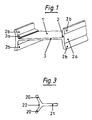
- a double-T profile 1 of 500 mm high with 15 mm thick web 3 and 28 mm thick flanges 2 was rolled out in the last compression frame of a rolling mill, not shown, to a nominal flange width of 300 mm (FIG. 1).
- the flange sections 2 b were unfolded during the reversing operation, so that the side rolls of the compression frame, which were complementary to the flange sections 2 a, 2 b, could guide the profile 1 in the middle during the rolling process.
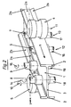
- the profile 1 was fed to the three-roll bending mill (Fig. 2).
- an essentially cylindrical pressure roller 4, 5 is arranged on both outer sides of the profile 1, with axes 1 1, 10 perpendicular to the rolling direction Z and to the axial direction X - Y.
- Both pressure rollers 4, 5 are provided with commercially available electric drives, not shown, which drive the pressure rollers 4, 5 according to the direction of rotation shown on axis 10 and cause the delivery of the pressure rollers 4, 5 in the X and Y directions.
- a symmetrically designed three-roll bending mill stand with the pressure roller 5 and the counter-rollers 8, 18 and 9, 19 is arranged on the rigid axes 14 and 15, respectively.
- the perspective view clearly shows the folding calibration process of the flange section 2 b in the bending line B between the three rollers 5, 8, 9.
- the finished double T-section 1 has straight, parallel flanges 2.
- Fig. 3 shows a T-profile with web 21, the flange portions 20 are folded out symmetrically to the web 21, so that the web 21 is formed in the middle during rolling.
- the flange sections 20 can be hingedly calibrated with a three-roll bending mill similar to that in FIG.
- the process is not limited to symmetrical profiles; In the same way, isosceles or isosceles angle profiles or U profiles and similar rolling stock can be finished.
- the type of roll stands is not limited to a three-roll bending roll stand; if necessary, a double system with two bending lines can be realized with two pressure rollers and three counter rollers. The principle of the three-roll bending process is thus retained.
- FIG. 4 Another solution for the same problem is shown in FIG. 4.
- a wide flange beam 900 mm high with parallel flange surfaces, flange width 300 mm, web thickness 20 mm and flange thickness 35 mm was rolled out with the flanges 27 a, b unfolded to the nominal dimensions mentioned.
- the profile sections 27 a, 27 b are folded by delivering the driven pressure roller 25 (illustration on the left).
- the finished profile with a straight flange 30 is shown to scale in the right half of FIG. 4. So that the web 29 does not buckle due to the pressure roller craters, it is supported by the top roller 23 and the bottom roller 24, leaving the 30 mm web / flange radius 28 free. In the absence of contact with the inner flange surfaces, no frictional wear can occur on the support rollers 23, 24.
- the invention also includes very narrow support rollers 23, 24 of variable diameter, which support the first profile section or web 29 only to a small width sideways of the radius 28 and do not touch the web 29 in their central region.
Landscapes
- Engineering & Computer Science (AREA)
- Mechanical Engineering (AREA)
- Metal Rolling (AREA)
- Heat Treatment Of Steel (AREA)
- Bending Of Plates, Rods, And Pipes (AREA)
Priority Applications (1)
| Application Number | Priority Date | Filing Date | Title |
|---|---|---|---|
| AT89102664T ATE94433T1 (de) | 1988-02-17 | 1989-02-16 | Fertigwalzverfahren fuer profile. |
Applications Claiming Priority (2)
| Application Number | Priority Date | Filing Date | Title |
|---|---|---|---|
| DE3805364A DE3805364A1 (de) | 1988-02-17 | 1988-02-17 | Fertigwalzverfahren fuer profile |
| DE3805364 | 1988-02-17 |
Publications (3)
| Publication Number | Publication Date |
|---|---|
| EP0329132A2 true EP0329132A2 (fr) | 1989-08-23 |
| EP0329132A3 EP0329132A3 (fr) | 1991-01-02 |
| EP0329132B1 EP0329132B1 (fr) | 1993-09-15 |
Family
ID=6347829
Family Applications (1)
| Application Number | Title | Priority Date | Filing Date |
|---|---|---|---|
| EP89102664A Expired - Lifetime EP0329132B1 (fr) | 1988-02-17 | 1989-02-16 | Procédé pour le laminage final de profilés |
Country Status (6)
| Country | Link |
|---|---|
| US (1) | US4942753A (fr) |
| EP (1) | EP0329132B1 (fr) |
| JP (1) | JPH01309702A (fr) |
| AT (1) | ATE94433T1 (fr) |
| DE (2) | DE3805364A1 (fr) |
| ES (1) | ES2043907T3 (fr) |
Families Citing this family (13)
| Publication number | Priority date | Publication date | Assignee | Title |
|---|---|---|---|---|
| DE3832392C2 (de) * | 1988-09-23 | 1996-07-11 | Schloemann Siemag Ag | Formstahl-Walzwerk |
| US5241735A (en) * | 1991-06-10 | 1993-09-07 | Emerson Electric Co. | Radial saw arm construction |
| US6604397B2 (en) | 2001-02-05 | 2003-08-12 | Dietrich Industries, Inc. | Rollforming machine |
| US6928848B2 (en) * | 2003-03-27 | 2005-08-16 | Ford Motor Company | Flanging processes with radial compression of the blank stretched surface |
| DE10339957B3 (de) * | 2003-08-25 | 2005-01-13 | Peiner Träger GmbH | Doppel-T-förmiges Spundwandprofil aus Stahl und Werkzeug zur Herstellung des Spundwandprofils |
| DE102008050366B4 (de) * | 2008-10-02 | 2010-06-17 | Data M Sheet Metal Solutions Gmbh | System zum Kaltwalzprofilieren von Profilen mit veränderlichem Querschnitt |
| EP2707155B1 (fr) * | 2011-05-13 | 2014-12-03 | Mannstaedt GmbH | Procédé et dispositif pour la fabrication de profilés métalliques avec une distance entre semelles à très faible tolérance |
| KR101350716B1 (ko) * | 2011-11-29 | 2014-01-14 | 주식회사 성우하이텍 | 롤 포밍 방법 및 이를 이용하여 생산되는 성형빔 |
| JP6394408B2 (ja) * | 2015-01-16 | 2018-09-26 | 新日鐵住金株式会社 | H形鋼の中間ユニバーサル圧延ロール及び中間ユニバーサル圧延機 |
| US10603761B2 (en) * | 2016-06-06 | 2020-03-31 | United Technologies Corporation | Deep roll peening system and method |
| CN109622611B (zh) * | 2018-12-20 | 2024-03-08 | 山东钢铁股份有限公司 | 一种带锁口的h型钢及其轧制方法和轧制装置 |
| CN111745049B (zh) * | 2020-06-02 | 2022-06-14 | 广州众山精密科技有限公司 | 导轨异型材加工组模及其一种导轨异型材的加工方法 |
| CN112246863B (zh) * | 2020-08-25 | 2023-03-17 | 山东润金重工科技有限公司 | 一种h型钢加工方法及装置 |
Family Cites Families (18)
| Publication number | Priority date | Publication date | Assignee | Title |
|---|---|---|---|---|
| DE240433C (fr) * | ||||
| FR369516A (fr) * | 1906-09-05 | 1907-01-14 | Wilhelm Schroer | Procédé de fabrication des fers profilés en forme de simple ou de double t. |
| FR370825A (fr) * | 1907-10-21 | 1907-02-20 | Hugo Sack | Procédé de laminage de poutrelles à I |
| DE254977C (de) * | 1915-11-23 | 1912-12-18 | Verfahren zum Auswalzen von I- und U-Eisen mit parallelflächigen Flanschen in Universalwalzwerken unter Abbiegen de Flanschen | |
| US1385644A (en) * | 1920-01-15 | 1921-07-26 | Alvin L Roberts | Universal mill |
| US1812246A (en) * | 1928-12-27 | 1931-06-30 | William C Oberg | Method of making flanged shapes |
| US1856269A (en) * | 1930-09-25 | 1932-05-03 | Bethlehem Steel Corp | Method and means for rolling channel sections |
| DE721478C (de) * | 1936-04-07 | 1942-06-06 | Ilseder Huette | Vorrichtung zum gleichzeitigen Zurueckbiegen der beim Walzvorgang aufgerichteten Flanschen oder Flanschenenden von doppel-T-foermigen Profileisen |
| DE219152C (de) * | 1959-07-22 | 1910-02-16 | Verfahren und Walzwerk zur Herstellung von I-Profileisen mit parallelflächigen Flanschen | |
| SU599863A1 (ru) * | 1975-12-22 | 1978-04-19 | Предприятие П/Я Г-4774 | Способ прокатки двутавровых балок |
| JPS5921681B2 (ja) * | 1978-09-12 | 1984-05-22 | 川崎製鉄株式会社 | H形鋼の製造方法 |
| JPS55126301A (en) * | 1979-03-23 | 1980-09-30 | Sumitomo Metal Ind Ltd | Manufacture of parallel flange channel |
| JPS58135705A (ja) * | 1982-02-06 | 1983-08-12 | Sumitomo Metal Ind Ltd | H形鋼の圧延方法 |
| JPS60240303A (ja) * | 1984-05-16 | 1985-11-29 | Hitachi Ltd | 長尺型材の製造方法 |
| DE3521949C2 (de) * | 1984-06-25 | 1994-05-26 | Schloemann Siemag Ag | Universalwalzgerüst |
| JPS6174708A (ja) * | 1984-09-19 | 1986-04-17 | Kawasaki Steel Corp | ユニバ−サル圧延機 |
| JPS61283401A (ja) * | 1985-06-07 | 1986-12-13 | Nippon Steel Corp | 形鋼の熱間圧延法 |
| JPS62282707A (ja) * | 1986-05-30 | 1987-12-08 | Nippon Steel Corp | フランジを有する形材の圧延装置列 |
-
1988
- 1988-02-17 DE DE3805364A patent/DE3805364A1/de not_active Withdrawn
-
1989
- 1989-02-15 US US07/311,608 patent/US4942753A/en not_active Expired - Fee Related
- 1989-02-16 EP EP89102664A patent/EP0329132B1/fr not_active Expired - Lifetime
- 1989-02-16 DE DE89102664T patent/DE58905573D1/de not_active Expired - Fee Related
- 1989-02-16 JP JP1035196A patent/JPH01309702A/ja active Pending
- 1989-02-16 AT AT89102664T patent/ATE94433T1/de not_active IP Right Cessation
- 1989-02-16 ES ES89102664T patent/ES2043907T3/es not_active Expired - Lifetime
Also Published As
| Publication number | Publication date |
|---|---|
| ATE94433T1 (de) | 1993-10-15 |
| DE58905573D1 (de) | 1993-10-21 |
| ES2043907T3 (es) | 1994-01-01 |
| EP0329132B1 (fr) | 1993-09-15 |
| US4942753A (en) | 1990-07-24 |
| JPH01309702A (ja) | 1989-12-14 |
| EP0329132A3 (fr) | 1991-01-02 |
| DE3805364A1 (de) | 1989-08-31 |
Similar Documents
| Publication | Publication Date | Title |
|---|---|---|
| EP0256409B2 (fr) | Procédé de fabrication de profils | |
| EP0454619B1 (fr) | Machine de cintrage d'une tôle en forme de cylindre | |
| EP0329132B1 (fr) | Procédé pour le laminage final de profilés | |
| DE3636478C2 (de) | Verfahren zum Walzen von Fertigprofilen aus einem Vorprofil | |
| EP0405065A2 (fr) | Procédé pour la fabrication de profilés creux rectangulaires en acier à épaisseur de paroi différente | |
| DE2940473A1 (de) | Verfahren und vorrichtung zur herstellung von metallprofilen | |
| DE2532710A1 (de) | Walzwerk zur herstellung nahtloser stahlrohre | |
| DE2437545C3 (de) | Verfahren zum Walzen von Metallstäben | |
| DE69108373T2 (de) | Führungsvorrichtung für das Walzen von Profilen. | |
| DE19901187C2 (de) | Vorrichtung zum kontinuierlichen Walzen eines Blechbandes zu einem Profil mit im Querschnitt geraden Profilschenkeln, insbesondere zum Herstellen eines längsgeschweißten Rechteckrohres | |
| DE102004040257A1 (de) | Vorrichtung zum Walzprofilieren von Kaltprofilen | |
| DE2114346A1 (de) | Verfahren und Vorrichtung zum Vorwalzen von Brammen bezueglich ihrer Breite | |
| EP0653253A1 (fr) | Procédé pour laminer des profilés finis à partir d'ébanches par un arrangement de cages de laminoir à entraînement reversible | |
| DE1299587B (de) | Vorwalzstrasse fuer ó±-Profiltraeger | |
| DE3220921C2 (fr) | ||
| DE69209632T2 (de) | Verfahren und Vorrichtung zum Walzen von Metallen zur Herstellung von rundem Stabmaterial oder Walzdraht aus rundem Stab- oder Drahtmaterial mit grösserem Durchmesser | |
| DE2902788C2 (de) | Verfahren zum Walzen von Draht oder Stäben | |
| DE69004558T2 (de) | Vorrichtung zum Walzen und Längsteilen ohne Verwindung und Verfahren zur Herstellung von Bewehrungsstäben. | |
| DE29980239U1 (de) | Walzwerk mit zweidimensional gesteuerter Walzendurchbiegung | |
| DE69921911T2 (de) | Rollenlagerung mit Dreiachsenfreiheit | |
| DE2529405A1 (de) | Verfahren zum profilwalzen | |
| EP2604351A1 (fr) | Laminage des profiles | |
| AT390741B (de) | Walzwerk, insbesondere kaltwalzwerk | |
| DE1814950B2 (de) | Universalgerüst zum Herstellen von asymmetrischen, H-förmigen Stahlprofilen | |
| DE69623208T2 (de) | Verfahren und vorrichtung zum warmwalzen von h-stahlträgern |
Legal Events
| Date | Code | Title | Description |
|---|---|---|---|
| PUAI | Public reference made under article 153(3) epc to a published international application that has entered the european phase |
Free format text: ORIGINAL CODE: 0009012 |
|
| AK | Designated contracting states |
Kind code of ref document: A2 Designated state(s): AT BE CH DE ES FR GB GR IT LI LU NL SE |
|
| 17P | Request for examination filed |
Effective date: 19891218 |
|
| PUAL | Search report despatched |
Free format text: ORIGINAL CODE: 0009013 |
|
| AK | Designated contracting states |
Kind code of ref document: A3 Designated state(s): AT BE CH DE ES FR GB GR IT LI LU NL SE |
|
| RAP3 | Party data changed (applicant data changed or rights of an application transferred) |
Owner name: PREUSSAG STAHL AKTIENGESELLSCHAFT |
|
| D17Q | First examination report despatched (deleted) | ||
| GRAA | (expected) grant |
Free format text: ORIGINAL CODE: 0009210 |
|
| AK | Designated contracting states |
Kind code of ref document: B1 Designated state(s): AT BE CH DE ES FR GB GR IT LI LU NL SE |
|
| REF | Corresponds to: |
Ref document number: 94433 Country of ref document: AT Date of ref document: 19931015 Kind code of ref document: T |
|
| REF | Corresponds to: |
Ref document number: 58905573 Country of ref document: DE Date of ref document: 19931021 |
|
| ET | Fr: translation filed | ||
| ITF | It: translation for a ep patent filed | ||
| REG | Reference to a national code |
Ref country code: ES Ref legal event code: FG2A Ref document number: 2043907 Country of ref document: ES Kind code of ref document: T3 |
|
| GBT | Gb: translation of ep patent filed (gb section 77(6)(a)/1977) |
Effective date: 19931213 |
|
| REG | Reference to a national code |
Ref country code: GR Ref legal event code: FG4A Free format text: 3009639 |
|
| EPTA | Lu: last paid annual fee | ||
| PLBE | No opposition filed within time limit |
Free format text: ORIGINAL CODE: 0009261 |
|
| STAA | Information on the status of an ep patent application or granted ep patent |
Free format text: STATUS: NO OPPOSITION FILED WITHIN TIME LIMIT |
|
| 26N | No opposition filed | ||
| PGFP | Annual fee paid to national office [announced via postgrant information from national office to epo] |
Ref country code: FR Payment date: 19950113 Year of fee payment: 7 |
|
| PGFP | Annual fee paid to national office [announced via postgrant information from national office to epo] |
Ref country code: SE Payment date: 19950116 Year of fee payment: 7 Ref country code: AT Payment date: 19950116 Year of fee payment: 7 |
|
| PGFP | Annual fee paid to national office [announced via postgrant information from national office to epo] |
Ref country code: GB Payment date: 19950119 Year of fee payment: 7 Ref country code: CH Payment date: 19950119 Year of fee payment: 7 |
|
| PGFP | Annual fee paid to national office [announced via postgrant information from national office to epo] |
Ref country code: GR Payment date: 19950125 Year of fee payment: 7 |
|
| PGFP | Annual fee paid to national office [announced via postgrant information from national office to epo] |
Ref country code: BE Payment date: 19950126 Year of fee payment: 7 |
|
| EAL | Se: european patent in force in sweden |
Ref document number: 89102664.3 |
|
| PGFP | Annual fee paid to national office [announced via postgrant information from national office to epo] |
Ref country code: LU Payment date: 19950201 Year of fee payment: 7 Ref country code: DE Payment date: 19950201 Year of fee payment: 7 |
|
| PGFP | Annual fee paid to national office [announced via postgrant information from national office to epo] |
Ref country code: ES Payment date: 19950208 Year of fee payment: 7 |
|
| PGFP | Annual fee paid to national office [announced via postgrant information from national office to epo] |
Ref country code: NL Payment date: 19950228 Year of fee payment: 7 |
|
| PG25 | Lapsed in a contracting state [announced via postgrant information from national office to epo] |
Ref country code: LU Free format text: LAPSE BECAUSE OF NON-PAYMENT OF DUE FEES Effective date: 19960216 Ref country code: GB Effective date: 19960216 Ref country code: AT Effective date: 19960216 |
|
| PG25 | Lapsed in a contracting state [announced via postgrant information from national office to epo] |
Ref country code: SE Effective date: 19960217 Ref country code: ES Free format text: LAPSE BECAUSE OF NON-PAYMENT OF DUE FEES Effective date: 19960217 |
|
| PG25 | Lapsed in a contracting state [announced via postgrant information from national office to epo] |
Ref country code: LI Free format text: LAPSE BECAUSE OF NON-PAYMENT OF DUE FEES Effective date: 19960228 Ref country code: CH Free format text: LAPSE BECAUSE OF NON-PAYMENT OF DUE FEES Effective date: 19960228 Ref country code: BE Effective date: 19960228 |
|
| BERE | Be: lapsed |
Owner name: PREUSSAG STAHL A.G. Effective date: 19960228 |
|
| PG25 | Lapsed in a contracting state [announced via postgrant information from national office to epo] |
Ref country code: GR Free format text: THE PATENT HAS BEEN ANNULLED BY A DECISION OF A NATIONAL AUTHORITY Effective date: 19960831 |
|
| PG25 | Lapsed in a contracting state [announced via postgrant information from national office to epo] |
Ref country code: NL Effective date: 19960901 |
|
| GBPC | Gb: european patent ceased through non-payment of renewal fee |
Effective date: 19960216 |
|
| REG | Reference to a national code |
Ref country code: CH Ref legal event code: PL |
|
| PG25 | Lapsed in a contracting state [announced via postgrant information from national office to epo] |
Ref country code: FR Effective date: 19961031 |
|
| REG | Reference to a national code |
Ref country code: GR Ref legal event code: MM2A Free format text: 3009639 |
|
| NLV4 | Nl: lapsed or anulled due to non-payment of the annual fee |
Effective date: 19960901 |
|
| PG25 | Lapsed in a contracting state [announced via postgrant information from national office to epo] |
Ref country code: DE Effective date: 19961101 |
|
| REG | Reference to a national code |
Ref country code: FR Ref legal event code: ST |
|
| REG | Reference to a national code |
Ref country code: ES Ref legal event code: FD2A Effective date: 19990405 |
|
| PG25 | Lapsed in a contracting state [announced via postgrant information from national office to epo] |
Ref country code: IT Free format text: LAPSE BECAUSE OF NON-PAYMENT OF DUE FEES;WARNING: LAPSES OF ITALIAN PATENTS WITH EFFECTIVE DATE BEFORE 2007 MAY HAVE OCCURRED AT ANY TIME BEFORE 2007. THE CORRECT EFFECTIVE DATE MAY BE DIFFERENT FROM THE ONE RECORDED. Effective date: 20050216 |