EP0329235A2 - Appareil pour le pliage de morceaux de pâte - Google Patents
Appareil pour le pliage de morceaux de pâte Download PDFInfo
- Publication number
- EP0329235A2 EP0329235A2 EP89200317A EP89200317A EP0329235A2 EP 0329235 A2 EP0329235 A2 EP 0329235A2 EP 89200317 A EP89200317 A EP 89200317A EP 89200317 A EP89200317 A EP 89200317A EP 0329235 A2 EP0329235 A2 EP 0329235A2
- Authority
- EP
- European Patent Office
- Prior art keywords
- conveyance
- mandrel
- bending
- mandrels
- product
- Prior art date
- Legal status (The legal status is an assumption and is not a legal conclusion. Google has not performed a legal analysis and makes no representation as to the accuracy of the status listed.)
- Granted
Links
- 238000005452 bending Methods 0.000 title claims abstract description 60
- 230000004087 circulation Effects 0.000 claims abstract description 3
- 238000007493 shaping process Methods 0.000 claims description 43
- 230000008093 supporting effect Effects 0.000 claims description 15
- 238000011144 upstream manufacturing Methods 0.000 claims description 11
- 230000008878 coupling Effects 0.000 claims description 3
- 238000010168 coupling process Methods 0.000 claims description 3
- 238000005859 coupling reaction Methods 0.000 claims description 3
- 230000005484 gravity Effects 0.000 claims description 2
- 230000000875 corresponding effect Effects 0.000 description 4
- 229910052729 chemical element Inorganic materials 0.000 description 2
- 230000001419 dependent effect Effects 0.000 description 2
- 230000006870 function Effects 0.000 description 2
- 230000002452 interceptive effect Effects 0.000 description 2
- 230000032258 transport Effects 0.000 description 2
- 239000006096 absorbing agent Substances 0.000 description 1
- 230000009286 beneficial effect Effects 0.000 description 1
- 239000000969 carrier Substances 0.000 description 1
- 238000011109 contamination Methods 0.000 description 1
- 235000012830 plain croissants Nutrition 0.000 description 1
- 230000000284 resting effect Effects 0.000 description 1
- 230000035939 shock Effects 0.000 description 1
Images
Classifications
-
- A—HUMAN NECESSITIES
- A21—BAKING; EDIBLE DOUGHS
- A21C—MACHINES OR EQUIPMENT FOR MAKING OR PROCESSING DOUGHS; HANDLING BAKED ARTICLES MADE FROM DOUGH
- A21C9/00—Other apparatus for handling dough or dough pieces
- A21C9/08—Depositing, arranging and conveying apparatus for handling pieces, e.g. sheets of dough
- A21C9/088—Folding or bending discrete dough pieces or dough strips
Definitions
- the invention relates to a device for bending an elongated dough product, comprising a first endless conveyance means which is suitable for receiving and conveying on a part of a conveyance surface thereof a row of products at a predetermined spacing from each other, the center line of each product running essentially perpendicular to the conveyance direction when it is received, a mandrel having a center line crossing the first conveyance means, means of movement for moving the mandrel in the conveyance direction in the conveyance path of the products and then back outside the conveyance path, and bending means arranged in a bending region on either side of the center of the conveyance path for bending a product around the mandrel.
- a device of this sort is known from the European Patent Application EP 0,307,903.
- the mandrel is formed by the end of a piston rod of a cylinder which is disposed above the first conveyance means and which is attached to a slide with which the cylinder can be moved to and fro in a vertical plane running through the center line of the conveyance path of the dough products.
- the slide reaches the most upstream position thereof, the piston rod is forced out of the cylinder.
- the slide is then moved in the conveyance direction of the first conveyance means.
- the mandrel formed by the end of the piston rod is able to intercept a dough product on the first conveyance means, after which the product can also be moved by the mandrel over the first conveyance means.
- the mandrel In the bending region the mandrel is moved between two stationary shaping elements so that the dough product is bent essentially into a U shape therebetween. After the mandrel has passed the stationary shaping elements, the piston rod with the mandrel thereon is pulled up by the cylinder through a height which is greater than the thickness of the dough product and the slide is moved back to the most upstream position thereof. This cycle is continuously repeated.
- the slide requires time to move from the most downstream position to the most upstream position thereof. Since the slide, starting from the most upstream position thereof, also has to be back again in this position when the first conveyance means has been moved over the pre-determined spacing between the dough products, the slide has to be moved in the downstream direction more rapidly than the first transport means.
- the known device is only suitable for bending the dough products into a U shape. This presents a drawback since a bent dough product may become straighter during subsequent processing so that a desired U shape is not maintained, while it is often also desirable to bend the ends of the dough product towards each other and even over each other.
- the object of the invention is to eliminate the drawbacks of the known device.
- the mandrel is a mandrel of a row, closed in itself of a number of mandrels, that the mandrels are connected to such an endless conveyance means at the predetermined spacing from each other that each mandrel extends substantially vertically from the conveyance surface when reaching said conveyance surface part, and that the mandrels are moved continuously in the conveyance surface in a circulation direction with substantially the speed of the first conveyance means.
- a simple embodiment of the device according to the invention is obtained if the conveyance means to which the mandrels are connected is the first conveyance means.
- a preferred embodiment of the device according to the invention is characterized in that the conveyance means to which the mandrels are connected is a second conveyance means, that the first conveyance means has a number of passages at the predetermined spacing, and in that the conveyance means are so disposed and the conveyance means so driven that, during conveyance, the mandrels are fed into the passages from below upstream of the bending region and the mandrels are fed out of the passages downstream of the bending region.
- the second conveyance means is driven by means of drive means and the first conveyance means is moved along by the second conveyance means by the mandrels projec ting through the passages.
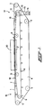
- the device according to the invention shown schematically in side view in Figure 1 comprises a first conveyance means formed by an endless conveyor belt 1, disposed around four rollers 2 to 5 with horizontal rotary shafts mounted in a stationary frame which is not shown.
- a second conveyance means formed by an endless chain 7 which is guided round four sprocket wheels 8 to 11 with horizontal rotary shafts mounted in the frame.
- the shaft of the sprocket wheel 10 has on it another sprocket wheel 12 which is coupled via a chain 13 to the shaft of a motor 14.
- the motor 14 is capable of driving the chain 7 in the direction indicated by the arrow 15.
- a number of mandrels 16 are provided at equal intervals on the chain 7, projecting in a vertical plane from the chain 7.
- Passages 17 ( Figure 2) are formed in the conveyor belt 1 in the vertical plane of the mandrels 16 at the same intervals as those of the mandrels 16.
- the pulleys 2 and 5 and the sprocket wheels 8 to 11 are disposed at such heights that, on the upstream side 18 of the device, the chain 7 is guided upwards with a slight slope from the sprocket wheel 11 to the sprocket wheel 8 and on the downstream side 19 of the device it is guided downwards with a slight slope from the sprocket wheel 9 to the sprocket wheel 10, with the mandrels 16 being entirely below the level of the conveyor belt 1 at the sprocket wheels 10 and 11 and being conveyed gradually out of the passages 17 in the area between the sprocket wheels 9 and 10.
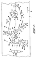
- Figure 2 shows a top view of a part of the conveyor belt 1 of the device of Figure 1, with above it the bending means shown schematically in Figure 1 by means of the rectangle 20.
- the bending means 20 comprise a number of movable elements, which in Figure 2 are shown in their rest position.
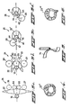
- the bending of an elongated dough product such as 22 will be explained with reference to Figures 2 and 3a to 3d, whereby in Figures 3b to 3d the movable elements are in a position differing from their rest position.
- the connection of a number of parts of the bending means 20 to the frame is indicated by the symbol 23 in Figure 2.
- the part of the conveyor belt 1 shown in Figure 2 has three passages 17, through each of which a mandrel 16 projects upwards.
- each dough product 22 passes through a first bending station 24 and then a second bending station 25.
- the bending station 24 has stationary arc shaping elements 26, 27 on either side of the center line of the conveyance path.
- the distance between the arc shaping elements 26, 27 is shorter than the length of an elongated dough product 22, so that during the conveyance thereof, the dough product 22 is bent from the shape shown in Figure 3a, via the shape shown in Figure 3b between the arc shaping elements 26 and 27, depending on the distance between the elements 26 and 27, into an arch or U shape.
- the second station 25 has a first movable shaping element 28 and a second movable shaping element 29, each of which is fixed to a respective lever which is rotatable via a hinge 30, 31 with a vertical axis of rotation.
- the lever in question has an articulated arm with partial arms 34 and 35, 36 and 37 coupled by means of a hinge 32, 33 respectively with vertical axis of rotation, the movable shaping element 28, 29 being connected to the partial arm 34, 36, and an arm 38, 39 to the partial arm 35, 37 respectively.
- follow-on elements 40, 41 are provided at the end of the arms 38, 39 in the path of the mandrels 16.
- the movable shaping element 28 and the follow-on element 40 of the one lever are disposed in the conveyance direction staggered relative to the movable shaping element 29 and the follow-on element 41 of the other lever.
- the follow-on elements 40, 41 are provided at a level higher than the top surface of the dough products 22 and rest against the mandrels 16 during passing of the mandrels 16, so that the lever in question with the movable shaping elements 28, 29 will swing in the direction of the arrows 42 and 43. This will cause first one leg 44 of a dough product 22′ bent into a U shape in the first bending station 24 to be bent against the mandrel 16 in question (Figure 3c) and then the other leg 45 against the earlier bent leg 44 (figure 3d), so that a bent dough product 22 ⁇ ( Figure 4) is obtained.
- the shape of the follow-on elements 40, 41 are selected dependent on the shape of the products 22′ supplied and of the desired shape of the products 22 ⁇ to be obtained so that the movable shaping elements 28 and 29 follow a corresponding predetermined pattern.
- the movable shaping elements 28, 29 can swing in the direction indicated by the double arrow 52, 53 by means of hinges 32, 33 coupled to the partial arms 34, 35 of one lever and 36, 37 of the other lever and springs 50, 51. This makes the second bending station 25 capable of processing dough products 22 with non-uniform shape and dimensions.
- the central section of the products 22 in the bending stations 24, 25 may be held by supporting elements in the same position relative to the mandrel 16 lying against it.
- the first bending station 24 has two supporting elements 54, 55 disposed on either side of the center line of the conveyance path in the bending area between the stationary shaping elements 26, 27 at the end of an arm 56, 57, said supporting elements being connected to a hinge 58, 59 with a vertical hinge pin, so that the supporting elements 54, 55 can rotate from the rest position shown in Figure 2 in the directions indicated by the arrows 60, 61 ( Figure 3b).
- the arm 57 via the hinge 59 with an arm 62 forms a lever.
- Hinges 63, 64 with vertical hinge pins are provided at such a point on the arms 56 and 62 and a coupling rod 65 is disposed between the hinges 63 and 64 in such a way that the supporting elements 54, 55 swing simultaneously with and symmetrically relative to the center line of the conveyance path.
- the coupling rod 65 is connected only to the hinges 63 and 64.
- the system with the supporting elements 54, 55 is forced in the rest position shown in Figure 2 against a stop element 66 by means of a spring 67 disposed between the frame 23 and the arm 62.
- the supporting elements 54, 55 will move over the dough product 22 during the swing, so that in addition to the function of positioning and maintaining the position of the dough product 22 they also have a bending function for the dough product 22.
- the second bending station 25 comprises a support element, which is in particular a roller 68, which has a horizontal axis, crossing the direction of conveyance 15 perpendicular and which extends symmetrically with respect to the center of the conveyance path.
- the roller 68 is, at the level of the products 22′, connected to the lower, free end of an arm 69, shown only in Figure 2 in cross section, descending from above the conveyance belt 1, being rotatable (in Figure 2 to the right) around a horizontal axis crossing the direction of movement 15 perpendicular and which is held by a spring, not shown, in the rest position shown in Figure 2.
- the location and the shape of the roller 68 and the length of the arm 69 are selected such, possibly dependent on the shape of the product 22′, that when a product 22′ lying against a mandrel 16 passes the roller 68 it is guided over the product 22′ and then over the mandrel 16, so that during bending the product 22′ is held against the mandrel 16.
- the dough product 22 ⁇ is obtained at the discharge side 19 of the device.
- the mandrels 16 are preferably in the form of a truncated cone having a diameter increasing towards the chain 7, and having a base angle of, for example, approximately 80°, preferably corresponding to the slope (10°) of the chain 7 at the supply part 18 and at the discharge part 19 of the device.
- the second bending station 25 Due to the special design of the second bending station 25, with the follow-on elements 40, 41 resting against the passing mandrels 16, the second bending station 25 always - regardless of the speed of the conveyor belt 1 - works in synchronism with the passing of the mandrels 16 and the dough products 22′ lying against them.
- the device Since in the preferred embodiment shown and described the device has only one motor, namely the motor 14, the device is simple to adapt tot he processing speed of a feed device and/or discharge device for dough products.
- the shaping elements 26 to 29 and the supporting elements 54, 55 and 68 are preferably roller elements with a vertical axis of rotation.
- the movable shaping elements 28, 29 can also be blade-shaped with a vertical axis of rotation, such as the blade-shaped shaping element 74 shown in Figure 5, which can be used instead of the movable shaping element 29. In this way the dough product 22′′′ bent in the first station 24 can be bent into a lyre shape, as shown in Figure 6.
- Other shapes of the dough products obtained by means of the bending means 20 can be obtained by suitable positioning of the different elements and choice of the lengths of the different arms.
- the bending means 20 could, if necessary, only comprise the bending station 24.
- the stop elements 48, 49, 66 and 71 are preferably telescopic shock absorber elements.
- the device according to the invention can be designed for processing a number of rows of dough products 22, instead of the single row shown.
- the movable elements, in particular the movable shaping elements 28, 29 of the bending means 20 can be moved, within the scope of the invention, by pneumatic means or the like which are controlled by control means which are coupled to the drive of the device and/or to detectors which detect the passage of the mandrels 16.
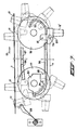
- Figure 7 shows schematically a side view of a part of the bending device according to the invention with the first conveyance means 1 and the second conveyance means 7.
- the second conveyance means 7 is indicated by a broken line and is guided around a wheel 77 and 78 upstream and downstream respectively.
- the second conveyance means 7 comprises, in particular, two parallel chains at a spacing from each other, between which, at least in positions which correspond to the passages 17 in the bending region, horizontal connecting rods 79 are disposed.
- Each mandrel 16′ of this embodiment has a passage 80 to allow the passage of a connecting rod 79 with play so that the mandrel 16′ can be rotated around the rod 79.
- Each connecting rod 79 is able to support a number of mandrels 16′ of a corresponding number of rows of mandrels 16′.
- Figure 7 shows by continuous lines only one mandrel 16′ of a single row (on the right hand side at the bottom). The other mandrels 16′ shown with dotted lines indicate some positions of the mandrel 16′ during conveyance thereof. The spacing between the passages 17 shown in Figure 7 are therefore also not equal to the actual spacings between the passages 17.
- the mandrel 16′ has at the end thereof which is not to be inserted through the conveyor belt 1 a horizontal protruding projection 81.
- the passage 80 and the projection 81 are disposed in front of the center line of the mandrel 16′ viewed in the conveyance direction 15.
- the center of gravity of the mandrel 16′ lies on the side of the passage 80 with the part of the mandrel 16′ which is inserted through the conveyance means 1.
- a curve disc 83 is disposed which has a guide groove 84 which has a wider capture part 85 at the inlet side thereof.
- the guide rod 82 and the guide tube 86 following it serve to give the mandrel 16′ an orientation such that the projection 81 thereof is captured in the wide part 85 of the guide groove 84 in the manner shown.
- the projection 82 will be guided into the guide groove 84, as a result of which the mandrel 16′ will be raised up and will gradually project increasingly through a passage 17.
- a guide tube 87 disposed beneath the conveyor belt 1 and having a part 88 sloping up from the region of the wheel 77 serves to keep the mandrel 16′ in a stable position.
- the mandrel 16′ preferably also has a cradle with two parallel flat legs, one of which is visible in Figure 7 and has the projection 81 for allowing the guide tubes 87 and 88 to pass between the legs with little play.
- a leaf spring 89 prevents the mandrel 16′ falling back at the end of raising it.
- the embodiment shown in Figure 7 has the important advantage that the device can be considerably shorter while at the same time the diameter of the passages 17 needs only to be very slightly larger than the largest diameter of the part of the mandrel 16′ projection through a passage 17.
- a simple embodiment of the device according to the invention is obtained if the mandrels 16 are connected to the first conveyance means 1.
- the second conveyance means 7 can be omitted then and the sprocket wheel 10 can be connected to the roller 2 for driving the first conveyance means 1.
- an embodiment comprising the second conveyance means 7 is preferred.
Landscapes
- Life Sciences & Earth Sciences (AREA)
- Engineering & Computer Science (AREA)
- Food Science & Technology (AREA)
- Manufacturing And Processing Devices For Dough (AREA)
- Shaping Of Tube Ends By Bending Or Straightening (AREA)
- Bending Of Plates, Rods, And Pipes (AREA)
Priority Applications (1)
| Application Number | Priority Date | Filing Date | Title |
|---|---|---|---|
| AT89200317T ATE95979T1 (de) | 1988-02-17 | 1989-02-09 | Vorrichtung zum biegen von teigstuecken. |
Applications Claiming Priority (2)
| Application Number | Priority Date | Filing Date | Title |
|---|---|---|---|
| NL8800402A NL8800402A (nl) | 1988-02-17 | 1988-02-17 | Deegstukbuiginrichting. |
| NL8800402 | 1988-02-17 |
Publications (3)
| Publication Number | Publication Date |
|---|---|
| EP0329235A2 true EP0329235A2 (fr) | 1989-08-23 |
| EP0329235A3 EP0329235A3 (en) | 1990-08-22 |
| EP0329235B1 EP0329235B1 (fr) | 1993-10-20 |
Family
ID=19851803
Family Applications (1)
| Application Number | Title | Priority Date | Filing Date |
|---|---|---|---|
| EP89200317A Expired - Lifetime EP0329235B1 (fr) | 1988-02-17 | 1989-02-09 | Appareil pour le pliage de morceaux de pâte |
Country Status (8)
| Country | Link |
|---|---|
| US (1) | US4961697A (fr) |
| EP (1) | EP0329235B1 (fr) |
| AT (1) | ATE95979T1 (fr) |
| AU (1) | AU610694B2 (fr) |
| CA (1) | CA1326612C (fr) |
| DE (1) | DE68909967T2 (fr) |
| ES (1) | ES2045381T3 (fr) |
| NL (1) | NL8800402A (fr) |
Cited By (7)
| Publication number | Priority date | Publication date | Assignee | Title |
|---|---|---|---|---|
| DE4039793A1 (de) * | 1990-12-13 | 1991-07-04 | Fritsch A Gmbh & Co Kg | Verfahren und vorrichtung zum biegen von teigstuecken, insbesondere croissants |
| ES2066647A2 (es) * | 1992-05-22 | 1995-03-01 | Soriano Angel Lozano | Unidad de continuo para la formacion de croissants. |
| EP0647404A1 (fr) * | 1993-10-08 | 1995-04-12 | Rheon Automatic Machinery Co. Ltd. | Appareil pour plier des croissants |
| EP1190623A1 (fr) * | 2000-09-26 | 2002-03-27 | Rheon Automatic Machinery Co., Ltd. | Procédé et dispositif pour la mise en forme d'un morceau de pâte |
| EP1226756A1 (fr) * | 2001-01-12 | 2002-07-31 | Vito Oronzo Perta | Dispositif de fabrication de "taralli" |
| WO2011144191A1 (fr) * | 2010-05-21 | 2011-11-24 | Fritsch Gmbh | Dispositif de formation de pâtons |
| EP2422623A3 (fr) * | 2010-08-25 | 2017-05-24 | Rheon Automatic Machinery Co., Ltd. | Pâte de croissant et procédé et machine de formation de cette pâte |
Families Citing this family (10)
| Publication number | Priority date | Publication date | Assignee | Title |
|---|---|---|---|---|
| US5354571A (en) * | 1992-04-27 | 1994-10-11 | Rheon Automatic Machinery Co., Ltd. | Method for aligning and bending individual round elongated dough pieces |
| DE4429382C2 (de) * | 1994-08-12 | 1996-09-19 | Uwe Trockels | Verfahren und Vorrichtung zum Formen und Einlegen von gebogenen Teigsträngen in Backbleche |
| IT1292364B1 (it) * | 1997-05-20 | 1999-01-29 | Barilla Alimentare Spa | Dispositivo per la formatura di prodotti da forno |
| ITMI20020464A1 (it) * | 2002-03-06 | 2003-09-08 | Arturo Colamussi | Apparato per la piegatura di croissant |
| DE10358069A1 (de) * | 2003-12-10 | 2005-07-14 | Cfs Kempten Gmbh | Gerollte Aufschnittscheiben |
| US8201493B2 (en) | 2008-01-03 | 2012-06-19 | Souhel Khanania | Oven |
| US10398148B2 (en) * | 2008-01-03 | 2019-09-03 | Souhel Khanania | Oven |
| WO2012165335A1 (fr) * | 2011-06-02 | 2012-12-06 | レオン自動機株式会社 | Procédé et dispositif pour la formation arrondie de produits alimentaires |
| US11517315B2 (en) | 2014-04-16 | 2022-12-06 | Cilag Gmbh International | Fastener cartridges including extensions having different configurations |
| EP3732973B1 (fr) | 2019-05-03 | 2024-07-03 | Radie B.V. | Dispositif de pliage de morceaux de pâte |
Family Cites Families (15)
| Publication number | Priority date | Publication date | Assignee | Title |
|---|---|---|---|---|
| US1089725A (en) * | 1912-06-19 | 1914-03-10 | Pfenninger Pretzel & Baking Company | Pretzel-making machine. |
| US1908640A (en) * | 1930-08-25 | 1933-05-09 | W E Dunn Mfg Company | Brick machine |
| US2057772A (en) * | 1934-02-05 | 1936-10-20 | Harry A Elliott | Machine for making pretzels |
| US2114951A (en) * | 1935-09-26 | 1938-04-19 | William M Young | Pretzel machine |
| US3232414A (en) * | 1963-03-29 | 1966-02-01 | Continental Can Co | Accelerating feed mechanism |
| AU464166B2 (en) * | 1972-04-20 | 1975-08-21 | Nabisco, Inc | Apparatus forand method of making pastry cups andthe like |
| SU431852A1 (fr) * | 1972-06-08 | 1974-06-15 | ||
| DE2603168C3 (de) * | 1975-02-06 | 1978-11-16 | Prohaska, Franz, Ing., Weiz, Steiermark (Oesterreich) | Vorrichtung zum etwa halbkreisförmigen Biegen von langgewirkten Backwarenrohlingen, insbesondere Kipferlrohlingen |
| DD135992A1 (de) * | 1977-11-04 | 1979-06-13 | Harry Riedel | Verfahren zur herstellung von geformten broetchen |
| FR2558339A1 (fr) * | 1984-01-20 | 1985-07-26 | Jouas Claude | Machine automatique pour la mise en forme d'articles, notamment d'articles alimentaires |
| US4582472A (en) * | 1985-03-21 | 1986-04-15 | Hanson Douglas R | Machine for forming croissants or other elongated products |
| DE3514361A1 (de) * | 1985-04-20 | 1986-10-23 | Bartels & Lüders GmbH Werk Brunsbüttel, 2212 Brunsbüttel | Verfahren und vorrichtung zur herstellung von hoernchen, vorzugsweise croissants |
| IT1215285B (it) * | 1985-07-01 | 1990-01-31 | M E Co Di Monaco E C S P A | Procedimento di panificazione per la fabbricazione di panetti croccanti a lunga conservazione erelativo impianto. |
| IT1222667B (it) * | 1987-09-16 | 1990-09-12 | Hans Ulrich Sotriffer | Dispositivo di bloccaggio rotatorio rapido ed automatico di un portautensile in un corpo di rotazione solidale ad esempio ad una macchina utensile o ad una fresatrice |
| FR2628080B1 (fr) * | 1988-03-03 | 1992-09-04 | Claire Fontaine Atel | Convoyeur elevateur du type a ameneurs |
-
1988
- 1988-02-17 NL NL8800402A patent/NL8800402A/nl not_active Application Discontinuation
-
1989
- 1989-02-09 ES ES89200317T patent/ES2045381T3/es not_active Expired - Lifetime
- 1989-02-09 DE DE89200317T patent/DE68909967T2/de not_active Expired - Fee Related
- 1989-02-09 EP EP89200317A patent/EP0329235B1/fr not_active Expired - Lifetime
- 1989-02-09 AT AT89200317T patent/ATE95979T1/de not_active IP Right Cessation
- 1989-02-14 CA CA000590971A patent/CA1326612C/fr not_active Expired - Fee Related
- 1989-02-15 AU AU29999/89A patent/AU610694B2/en not_active Ceased
- 1989-02-16 US US07/311,592 patent/US4961697A/en not_active Expired - Lifetime
Cited By (10)
| Publication number | Priority date | Publication date | Assignee | Title |
|---|---|---|---|---|
| DE4039793A1 (de) * | 1990-12-13 | 1991-07-04 | Fritsch A Gmbh & Co Kg | Verfahren und vorrichtung zum biegen von teigstuecken, insbesondere croissants |
| ES2066647A2 (es) * | 1992-05-22 | 1995-03-01 | Soriano Angel Lozano | Unidad de continuo para la formacion de croissants. |
| EP0647404A1 (fr) * | 1993-10-08 | 1995-04-12 | Rheon Automatic Machinery Co. Ltd. | Appareil pour plier des croissants |
| EP1190623A1 (fr) * | 2000-09-26 | 2002-03-27 | Rheon Automatic Machinery Co., Ltd. | Procédé et dispositif pour la mise en forme d'un morceau de pâte |
| US6833147B2 (en) | 2000-09-26 | 2004-12-21 | Rheon Automatic Machinery Co., Ltd. | Method and an apparatus for shaping a dough piece |
| EP1226756A1 (fr) * | 2001-01-12 | 2002-07-31 | Vito Oronzo Perta | Dispositif de fabrication de "taralli" |
| WO2011144191A1 (fr) * | 2010-05-21 | 2011-11-24 | Fritsch Gmbh | Dispositif de formation de pâtons |
| EP2826374A1 (fr) * | 2010-05-21 | 2015-01-21 | Fritsch GmbH | Dispositif de formation de pâtons |
| US9101145B2 (en) | 2010-05-21 | 2015-08-11 | Fritsch Gmbh | Device for forming dough pieces |
| EP2422623A3 (fr) * | 2010-08-25 | 2017-05-24 | Rheon Automatic Machinery Co., Ltd. | Pâte de croissant et procédé et machine de formation de cette pâte |
Also Published As
| Publication number | Publication date |
|---|---|
| ES2045381T3 (es) | 1994-01-16 |
| DE68909967D1 (de) | 1993-11-25 |
| CA1326612C (fr) | 1994-02-01 |
| AU610694B2 (en) | 1991-05-23 |
| DE68909967T2 (de) | 1994-04-21 |
| US4961697A (en) | 1990-10-09 |
| NL8800402A (nl) | 1989-09-18 |
| ATE95979T1 (de) | 1993-11-15 |
| EP0329235B1 (fr) | 1993-10-20 |
| EP0329235A3 (en) | 1990-08-22 |
| AU2999989A (en) | 1989-08-17 |
Similar Documents
| Publication | Publication Date | Title |
|---|---|---|
| EP0329235B1 (fr) | Appareil pour le pliage de morceaux de pâte | |
| EP0098733B1 (fr) | Système de traitement des oeufs | |
| EP0551177B1 (fr) | Appareil pour la production de croissants avec remplissages | |
| US4753336A (en) | Packaging machine | |
| US5609237A (en) | Cylindrical object tipping device and method | |
| US4645058A (en) | Apparatus for orienting eggs in a egg handling systems | |
| NL192658C (nl) | Samenstel voor het vervaardigen van croissant-vormige deegprodukten. | |
| JPH05193732A (ja) | 卵のごとき物品の受容または転送、垂直搬送および供給装置 | |
| US4411366A (en) | Device for grading products | |
| EP0345036B1 (fr) | Convoyeur avec distributeur | |
| US4956894A (en) | Apparatus for collecting fish eggs | |
| EP0185424A1 (fr) | Dispositif pour trier des produits | |
| US3446334A (en) | Bottle letdown mechanism | |
| US2796967A (en) | Egg aligner | |
| EP1190623B1 (fr) | Procédé et dispositif pour la mise en forme d'un morceau de pâte | |
| KR870000859B1 (ko) | 슬라이드 파스너 배출장치 | |
| NZ227992A (en) | Dough piece bending apparatus | |
| JP3069142B2 (ja) | 練り粉の索の長さを調節するための装置 | |
| US3905467A (en) | Article aligning apparatus | |
| US2241659A (en) | Feeding and centering mechanism | |
| EP1247770B1 (fr) | Dispositif de transfert de fruits entre deux convoyeurs arrangés à angle droit | |
| US3731798A (en) | Sizer conveyor | |
| US4228887A (en) | Rotary bottle discharge apparatus | |
| JPH051733U (ja) | 物品の排出装置 | |
| JPH0739852Y2 (ja) | 選別供給装置 |
Legal Events
| Date | Code | Title | Description |
|---|---|---|---|
| PUAI | Public reference made under article 153(3) epc to a published international application that has entered the european phase |
Free format text: ORIGINAL CODE: 0009012 |
|
| AK | Designated contracting states |
Kind code of ref document: A2 Designated state(s): AT BE CH DE ES FR GB IT LI LU NL SE |
|
| PUAL | Search report despatched |
Free format text: ORIGINAL CODE: 0009013 |
|
| RHK1 | Main classification (correction) |
Ipc: A21C 3/08 |
|
| AK | Designated contracting states |
Kind code of ref document: A3 Designated state(s): AT BE CH DE ES FR GB IT LI LU NL SE |
|
| 17P | Request for examination filed |
Effective date: 19900727 |
|
| 17Q | First examination report despatched |
Effective date: 19910917 |
|
| GRAA | (expected) grant |
Free format text: ORIGINAL CODE: 0009210 |
|
| ITF | It: translation for a ep patent filed | ||
| AK | Designated contracting states |
Kind code of ref document: B1 Designated state(s): AT BE CH DE ES FR GB IT LI LU NL SE |
|
| REF | Corresponds to: |
Ref document number: 95979 Country of ref document: AT Date of ref document: 19931115 Kind code of ref document: T |
|
| REF | Corresponds to: |
Ref document number: 68909967 Country of ref document: DE Date of ref document: 19931125 |
|
| ET | Fr: translation filed | ||
| EPTA | Lu: last paid annual fee | ||
| PLBE | No opposition filed within time limit |
Free format text: ORIGINAL CODE: 0009261 |
|
| STAA | Information on the status of an ep patent application or granted ep patent |
Free format text: STATUS: NO OPPOSITION FILED WITHIN TIME LIMIT |
|
| 26N | No opposition filed | ||
| EAL | Se: european patent in force in sweden |
Ref document number: 89200317.9 |
|
| REG | Reference to a national code |
Ref country code: CH Ref legal event code: PUE Owner name: SASIB BAKERY HOLLAND N.V. |
|
| REG | Reference to a national code |
Ref country code: GB Ref legal event code: 732E |
|
| REG | Reference to a national code |
Ref country code: FR Ref legal event code: TP |
|
| NLS | Nl: assignments of ep-patents |
Owner name: SASIB BAKERY HOLLAND N.V. TE ASPEREN. |
|
| REG | Reference to a national code |
Ref country code: ES Ref legal event code: PC2A Owner name: SASIB BAKERY HOLLAND N.V. |
|
| PGFP | Annual fee paid to national office [announced via postgrant information from national office to epo] |
Ref country code: GB Payment date: 19970305 Year of fee payment: 9 |
|
| PGFP | Annual fee paid to national office [announced via postgrant information from national office to epo] |
Ref country code: LU Payment date: 19970408 Year of fee payment: 9 |
|
| PG25 | Lapsed in a contracting state [announced via postgrant information from national office to epo] |
Ref country code: LU Free format text: LAPSE BECAUSE OF NON-PAYMENT OF DUE FEES Effective date: 19980209 Ref country code: GB Free format text: LAPSE BECAUSE OF NON-PAYMENT OF DUE FEES Effective date: 19980209 |
|
| GBPC | Gb: european patent ceased through non-payment of renewal fee |
Effective date: 19980209 |
|
| PGFP | Annual fee paid to national office [announced via postgrant information from national office to epo] |
Ref country code: DE Payment date: 20030319 Year of fee payment: 15 Ref country code: AT Payment date: 20030319 Year of fee payment: 15 |
|
| PGFP | Annual fee paid to national office [announced via postgrant information from national office to epo] |
Ref country code: ES Payment date: 20030320 Year of fee payment: 15 |
|
| PGFP | Annual fee paid to national office [announced via postgrant information from national office to epo] |
Ref country code: SE Payment date: 20030325 Year of fee payment: 15 Ref country code: CH Payment date: 20030325 Year of fee payment: 15 Ref country code: BE Payment date: 20030325 Year of fee payment: 15 |
|
| PGFP | Annual fee paid to national office [announced via postgrant information from national office to epo] |
Ref country code: NL Payment date: 20030331 Year of fee payment: 15 |
|
| PGFP | Annual fee paid to national office [announced via postgrant information from national office to epo] |
Ref country code: FR Payment date: 20030611 Year of fee payment: 15 |
|
| PG25 | Lapsed in a contracting state [announced via postgrant information from national office to epo] |
Ref country code: AT Free format text: LAPSE BECAUSE OF NON-PAYMENT OF DUE FEES Effective date: 20040209 |
|
| PG25 | Lapsed in a contracting state [announced via postgrant information from national office to epo] |
Ref country code: SE Free format text: LAPSE BECAUSE OF NON-PAYMENT OF DUE FEES Effective date: 20040210 Ref country code: ES Free format text: LAPSE BECAUSE OF NON-PAYMENT OF DUE FEES Effective date: 20040210 |
|
| PG25 | Lapsed in a contracting state [announced via postgrant information from national office to epo] |
Ref country code: BE Free format text: LAPSE BECAUSE OF NON-PAYMENT OF DUE FEES Effective date: 20040228 |
|
| PG25 | Lapsed in a contracting state [announced via postgrant information from national office to epo] |
Ref country code: LI Free format text: LAPSE BECAUSE OF NON-PAYMENT OF DUE FEES Effective date: 20040229 Ref country code: CH Free format text: LAPSE BECAUSE OF NON-PAYMENT OF DUE FEES Effective date: 20040229 |
|
| BERE | Be: lapsed |
Owner name: *SASIB BAKERY HOLLAND N.V. Effective date: 20040228 |
|
| PG25 | Lapsed in a contracting state [announced via postgrant information from national office to epo] |
Ref country code: NL Free format text: LAPSE BECAUSE OF NON-PAYMENT OF DUE FEES Effective date: 20040901 Ref country code: DE Free format text: LAPSE BECAUSE OF NON-PAYMENT OF DUE FEES Effective date: 20040901 |
|
| EUG | Se: european patent has lapsed | ||
| REG | Reference to a national code |
Ref country code: CH Ref legal event code: PL |
|
| PG25 | Lapsed in a contracting state [announced via postgrant information from national office to epo] |
Ref country code: FR Free format text: LAPSE BECAUSE OF NON-PAYMENT OF DUE FEES Effective date: 20041029 |
|
| NLV4 | Nl: lapsed or anulled due to non-payment of the annual fee |
Effective date: 20040901 |
|
| REG | Reference to a national code |
Ref country code: FR Ref legal event code: ST |
|
| PG25 | Lapsed in a contracting state [announced via postgrant information from national office to epo] |
Ref country code: IT Free format text: LAPSE BECAUSE OF NON-PAYMENT OF DUE FEES;WARNING: LAPSES OF ITALIAN PATENTS WITH EFFECTIVE DATE BEFORE 2007 MAY HAVE OCCURRED AT ANY TIME BEFORE 2007. THE CORRECT EFFECTIVE DATE MAY BE DIFFERENT FROM THE ONE RECORDED. Effective date: 20050209 |
|
| REG | Reference to a national code |
Ref country code: ES Ref legal event code: FD2A Effective date: 20040210 |