EP0329300A2 - Poliereinrichtung für Magnetplattensubstrat - Google Patents
Poliereinrichtung für Magnetplattensubstrat Download PDFInfo
- Publication number
- EP0329300A2 EP0329300A2 EP89300917A EP89300917A EP0329300A2 EP 0329300 A2 EP0329300 A2 EP 0329300A2 EP 89300917 A EP89300917 A EP 89300917A EP 89300917 A EP89300917 A EP 89300917A EP 0329300 A2 EP0329300 A2 EP 0329300A2
- Authority
- EP
- European Patent Office
- Prior art keywords
- polish
- roller
- assembly
- disk substrate
- tape
- Prior art date
- Legal status (The legal status is an assumption and is not a legal conclusion. Google has not performed a legal analysis and makes no representation as to the accuracy of the status listed.)
- Withdrawn
Links
- 239000000758 substrate Substances 0.000 title claims abstract description 70
- 238000005498 polishing Methods 0.000 title claims abstract description 38
- 239000004744 fabric Substances 0.000 abstract description 3
- 238000000034 method Methods 0.000 description 5
- PXHVJJICTQNCMI-UHFFFAOYSA-N Nickel Chemical compound [Ni] PXHVJJICTQNCMI-UHFFFAOYSA-N 0.000 description 2
- 239000000463 material Substances 0.000 description 2
- NPXOKRUENSOPAO-UHFFFAOYSA-N Raney nickel Chemical compound [Al].[Ni] NPXOKRUENSOPAO-UHFFFAOYSA-N 0.000 description 1
- 230000006835 compression Effects 0.000 description 1
- 238000007906 compression Methods 0.000 description 1
- 238000013500 data storage Methods 0.000 description 1
- 230000001788 irregular Effects 0.000 description 1
- 239000000696 magnetic material Substances 0.000 description 1
- 229910052751 metal Inorganic materials 0.000 description 1
- 239000002184 metal Substances 0.000 description 1
- 229910052759 nickel Inorganic materials 0.000 description 1
Images

Classifications
-
- B—PERFORMING OPERATIONS; TRANSPORTING
- B24—GRINDING; POLISHING
- B24B—MACHINES, DEVICES, OR PROCESSES FOR GRINDING OR POLISHING; DRESSING OR CONDITIONING OF ABRADING SURFACES; FEEDING OF GRINDING, POLISHING, OR LAPPING AGENTS
- B24B21/00—Machines or devices using grinding or polishing belts; Accessories therefor
- B24B21/004—Machines or devices using grinding or polishing belts; Accessories therefor using abrasive rolled strips
-
- B—PERFORMING OPERATIONS; TRANSPORTING
- B24—GRINDING; POLISHING
- B24B—MACHINES, DEVICES, OR PROCESSES FOR GRINDING OR POLISHING; DRESSING OR CONDITIONING OF ABRADING SURFACES; FEEDING OF GRINDING, POLISHING, OR LAPPING AGENTS
- B24B21/00—Machines or devices using grinding or polishing belts; Accessories therefor
- B24B21/04—Machines or devices using grinding or polishing belts; Accessories therefor for grinding plane surfaces
-
- B—PERFORMING OPERATIONS; TRANSPORTING
- B24—GRINDING; POLISHING
- B24B—MACHINES, DEVICES, OR PROCESSES FOR GRINDING OR POLISHING; DRESSING OR CONDITIONING OF ABRADING SURFACES; FEEDING OF GRINDING, POLISHING, OR LAPPING AGENTS
- B24B7/00—Machines or devices designed for grinding plane surfaces on work, including polishing plane glass surfaces; Accessories therefor
- B24B7/10—Single-purpose machines or devices
- B24B7/16—Single-purpose machines or devices for grinding end-faces, e.g. of gauges, rollers, nuts, piston rings
Definitions
- the present invention relates to polishing apparatus and more particularly, but not exclusively, to a polishing assembly for polishing the surface of a magnetic disk substrate as the disk is rotated.
- aluminium nickel disk substrate on which magnetic medium is deposited be very flat and have a uniform pattern to prevent flying head crashes and to keep the flying head at a constant spacing above the medium.
- the disk is polished with a fine abrasive cloth or tape so that scratches by the tape are circular arcs centered on the disk centre.
- this has been done by holding the tape against the disk surface with a cylindrical roller, called a presser, and slowly moving the cloth over the presser while rapidly rotating the disk. This technique of polishing the disk substrate has caused ripples on the polished surface of the disk substrate.
- US-A-4,347,689 describes a method and apparatus for burnishing a coated recording surface of a magnetic disk.
- An abrasive burnishing tape is oscillated laterally back and forth across the surface of the coated surface of the disk as it is rotated on a platen.
- the apparatus making up this burnishing device is significantly different from the polishing assembly according to the invention.
- US-A-4,514,937, US-A-4,412,400 and US-A-4,656,790 describe various types of apparatus and methods using an abrasive tape for burnishing a magnetic material surface of a magnetic disk.
- US-A-4,270,316 describes a process for evening out the amount of material removed from disks in polishing. While evening out material removed during polishing is an important consideration, the process described in this patent does not address the problem of ripples on a polished disk substrate surface upon completion of the polishing operation.
- US-A-3,971,163, US-A-2,802,311 and US-A-3,888,050 are of general interest as such describe apparatuses for polishing flexible lens, metal workpieces and workpieces having deeply curved surfaces.
- a magnetic disk substrate polishing assembly for polishing a surface of a disk substrate as the disk substrate is rotated, the assembly comprising: polish tape feed means for feeding polish tape onto a polish roller rotatably mounted on an assembly housing and disposed adjacent a surface of a disk substrate, and polish tape take up means for taking up the tape after the tape is fed round the polish roller, characterised in that the polish roller is mounted on the assembly housing for movement towards and away from the adjacent surface of the disk substrate and is biased by biasing means towards said surface with the polish tape between the polish roller and the surface.
- the invention provides a magnetic disk substrate polishing assembly having a polish roller which will conform to the surface contour of a magnetic disk substrate.
- the biasing means comprises at least one, and preferably two, coil springs mounted on the assembly housing to apply a bias force on the polish roller.
- the invention provides spring bias to the polish roller against the surface of a magnetic disk substrate, so that the polish roller will shift and conform to axial run out of the disk during the completion of the polishing operation.
- a magnetic disk substrate polishing assembly for polishing a surface of a disk substrate as the disk substrate is rotated, comprises a polish roller having an abrasive polish tape continuously fed thereon.
- the polish roller is rotatably mounted on an assembly housing with the polish roller disposed adjacent the rotating disk substrate.
- the polish roller is moved towards and pressed against the surface of the disk substrate with the polish tape therebetween.
- the polish roller is biased by coil springs in a direction towards and perpendicular to the surface of the disk substrate which allows the roller with polish tape thereon to conform to the surface of the disk substrate so as to reduce ripples in the polished surface when the polishing operation is completed.
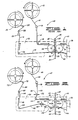
- a prior art magnetic disk substrate polishing assembly 10 ( Figure 1) includes a feed reel 12 from which an abrasive polishing tape 14 is fed onto a retaining idler 16 and round a first crowned idle roller 18. The tape 14 then passes around a fixed polish roller 22 and a second crowned idle roller 24. The rollers 18, 22 and 24 are rotatably mounted on a front assembly housing 20. The tape 14 then leaves the front assembly housing 20 whence it is received onto and between a knurled drive roller 26 and pinch roller 28, and round an idle roller 30 to be wound onto a take up reel 32.
- a rotating disk blank 34 mounted on a drive spindle 36 and attached thereto by a removable disk hub 38.
- the disk substrate 34 is rapidly rotated and the tape 14 moved slowly over the surface of the polish roller 22.
- the front assembly housing 20 is moved to the right, so that the tape 14 engages and polishes a front surface 33 of the disk substrate 34.
- the front assembly housing 20 is moved to the left dis-engaging the polish roller 22 and tape 14 from the front surface 33 of the disk substrate 34.
- the assembly includes a rear assembly housing 40 with a polish roller 22 and tape 14.
- this rear assembly housing 40 is moved to the right, so that the polish tape 14 engages and polishes the rear surface 35 of the disk substrate 34.
- the polish roller 22 is rigidly mounted in the assembly housing 20 or 40, the polish roller 22 is not free to move and conform to, or float on, the contoured surface of the disk substrate 34.
- the polish roller 22 with its tape 14 may tear the substrate, causing ripples thereon.
- a magnetic disk substrate polishing assembly 42 ( Figure 2) constructed in accordance with the present invention, for polishing a disk substrate 34, includes a feed reel 44 for feeding an abrasive polishing tape 46 onto a retaining idler 48 and then onto a tracking roller 50 which is adjustable either to the left or right in a horizontal plane (parallel to the axis of rotation of the disk substrate 34) as indicated by arrow 52. From the tracking roller 50, the tape 46 is fed round a crowned idle roller 54 rotatably mounted on a front assembly housing 56. The tape 46 is then received around a polish roller 58 rotatably mounted on the housing 56.
- the polish roller 58 is free to move towards and away from the disk substrate 34 and is spring biased towards the disk substrate 34 in a plane perpendicular to the disk substrate 34 as indicated by arrow 60.
- the tape 46 from the polish roller 58 is fed over a crowned tracking roller 62 and a crowned idle roller 64 before leaving the front assembly housing 56.
- the tracking roller 62 and idle roller 64 are rotatably mounted on the front assembly housing 56 with the tracking roller 62 adjustable up and down and left to right as indicated by arrows 66. Any change in the polishing operation that moves the tape 46 off the polish roller 58 can be compensated for by adjusting the tracking roller 62.
- Changes that can affect the tracking of the tape 46 on the polish roller 58 are a pressure change of the polish roller 58 against the disk substrate 34, a transverse speed change of the polish roller 58 across the disk substrate 34, and a change of the rotational speed of the disk substrate 34.
- the tape 46 leaves the front assembly housing 56, it is received onto and between a knurled drive roller 66 and pinch roller 68 and then round an idle roller 70 before being wound onto a take up reel 72.
- the rotating disk substrate 34 disposed adjacent to the polish roller 58 with tape 46 thereon, is mounted on the drive spindle 36 and attached thereto by the removable disk hub 38.
- the front assembly housing 56 ( Figures 3 and 4) includes first and second spaced side plates 76 and 78. Portions of the side plates 76 and 78 are cut away in Figure 3 to expose the ends of the polish roller 58 and tracking roller 62 rotatably mounted thereon.
- the tracking roller 62 is rotatably mounted in adjustment plates 80 and 82 adjustably attached to the side plates 76 and 78, respectively.
- Each adjustment plate is engaged by a vertical adjustment screw 84 and a horizontal adjustment screw 86.
- Each of the side plates 76 and 78 has a first slot 90 and a second aligned slot 100.
- a coil spring 88 is mounted in the first slot 90.
- One end of the coil spring 88 is received against a retaining block 92 whose position is adjustable by a screw 94.
- the other end of the coils spring 88 engages against one end of a transfer yoke 96, which end is engaged in the slot 90.
- the other end of the transfer yoke 96 is in the form of a slot pin 98 received in the second slot 100.
- Between the ends the transfer yoke 96 extends along side of the part of the side plate between the slots 90 and 100, and has a plate screwed thereto to embrace that part.
- the slot pin 98 in the first side plate 76 engages a notched first end 102 of a polish roller shaft 104
- the slot pin 98 in the second side plate 78 engages a notched second end 103 of the polish roller shaft 104.
- the front and rear assembly housings are moved simultaneously in opposite directions by the same distances, and that the bias forces applied to the respective polish rollers are equal and opposite. It will be appreciated that the polishing apparatus may have more general application to the polishing of flat surfaces. It will also be appreciated that a single coil spring may be used as the biasing means to apply a bias force to the polish roller.
Landscapes
- Engineering & Computer Science (AREA)
- Mechanical Engineering (AREA)
- Finish Polishing, Edge Sharpening, And Grinding By Specific Grinding Devices (AREA)
- Manufacturing Of Magnetic Record Carriers (AREA)
Applications Claiming Priority (2)
| Application Number | Priority Date | Filing Date | Title |
|---|---|---|---|
| US157824 | 1988-02-19 | ||
| US07/157,824 US4930259A (en) | 1988-02-19 | 1988-02-19 | Magnetic disk substrate polishing assembly |
Publications (1)
| Publication Number | Publication Date |
|---|---|
| EP0329300A2 true EP0329300A2 (de) | 1989-08-23 |
Family
ID=22565430
Family Applications (1)
| Application Number | Title | Priority Date | Filing Date |
|---|---|---|---|
| EP89300917A Withdrawn EP0329300A2 (de) | 1988-02-19 | 1989-01-31 | Poliereinrichtung für Magnetplattensubstrat |
Country Status (3)
| Country | Link |
|---|---|
| US (1) | US4930259A (de) |
| EP (1) | EP0329300A2 (de) |
| JP (1) | JPH0221420A (de) |
Cited By (1)
| Publication number | Priority date | Publication date | Assignee | Title |
|---|---|---|---|---|
| US6386946B1 (en) * | 2000-06-16 | 2002-05-14 | Mao-Sang Lin | Repair machine for compact disk |
Families Citing this family (23)
| Publication number | Priority date | Publication date | Assignee | Title |
|---|---|---|---|---|
| US5177903A (en) * | 1988-09-14 | 1993-01-12 | Farros Blatter Ag | Method and apparatus for copy-grinding and finishing of cylindrical and spherical surfaces |
| US5099615A (en) * | 1989-09-22 | 1992-03-31 | Exclusive Design Company, Inc. | Automated rigid-disk finishing system providing in-line process control |
| US5088240A (en) * | 1989-09-22 | 1992-02-18 | Exclusive Design Company, Inc. | Automated rigid-disk finishing system providing in-line process control |
| US4964242A (en) * | 1989-09-22 | 1990-10-23 | Exclusive Design Company | Apparatus for texturing rigid-disks used in digital magnetic recording systems |
| US5209027A (en) * | 1989-10-13 | 1993-05-11 | Tdk Corporation | Polishing of the rear surface of a stamper for optical disk reproduction |
| US5443415A (en) * | 1993-09-24 | 1995-08-22 | International Technology Partners, Inc. | Burnishing apparatus for flexible magnetic disks and method therefor |
| US5628676A (en) * | 1995-03-02 | 1997-05-13 | Exclusive Design Company | Counter-balance for disk texturizing apparatus |
| KR100189970B1 (ko) * | 1995-08-07 | 1999-06-01 | 윤종용 | 웨이퍼 연마장치 |
| JP3024947B2 (ja) * | 1997-07-03 | 2000-03-27 | 日本ミクロコーティング株式会社 | 研磨装置 |
| US5885143A (en) * | 1997-07-17 | 1999-03-23 | Hitachi Electronics Engineering Co., Ltd. | Disk texturing apparatus |
| US6155914A (en) * | 1997-09-22 | 2000-12-05 | Seagate Technologies, Llc | Apparatus for the application of an advanced texture process |
| US6196907B1 (en) | 1999-10-01 | 2001-03-06 | U.S. Dynamics Corporation | Slurry delivery system for a metal polisher |
| JP4268303B2 (ja) * | 2000-02-01 | 2009-05-27 | キヤノンアネルバ株式会社 | インライン型基板処理装置 |
| US6482072B1 (en) * | 2000-10-26 | 2002-11-19 | Applied Materials, Inc. | Method and apparatus for providing and controlling delivery of a web of polishing material |
| DE202005014430U1 (de) * | 2005-09-12 | 2005-11-24 | Lissmac Maschinenbau Und Diamantwerkzeuge Gmbh | Vorrichtung zum Bearbeiten eines Werkstücks |
| US20090264053A1 (en) * | 2008-04-21 | 2009-10-22 | Applied Materials, Inc. | Apparatus and methods for using a polishing tape cassette |
| US20090280730A1 (en) * | 2008-05-09 | 2009-11-12 | Solves Innovative Technology Pte Ltd | Burnishing apparatus and process |
| US8192249B2 (en) * | 2009-03-12 | 2012-06-05 | Hitachi Global Storage Technologies Netherlands, B.V. | Systems and methods for polishing a magnetic disk |
| DE102009055974A1 (de) * | 2009-11-27 | 2011-06-01 | Lissmac Maschinenbau Gmbh | Bearbeitungsstation und Vorrichtung zum Bearbeiten eines Werkstücks |
| US8727832B2 (en) * | 2011-09-27 | 2014-05-20 | HGST Netherlands B.V. | System, method and apparatus for enhanced cleaning and polishing of magnetic recording disk |
| EP2764954B1 (de) * | 2013-02-06 | 2016-05-25 | JOT Automation Oy | Maschinelles Bearbeitungswerkzeug |
| JP2014205233A (ja) * | 2013-03-19 | 2014-10-30 | パナソニック株式会社 | 部品の加工方法及び加工装置 |
| JP6204848B2 (ja) * | 2014-02-17 | 2017-09-27 | 株式会社荏原製作所 | 研磨装置および研磨方法 |
Family Cites Families (13)
| Publication number | Priority date | Publication date | Assignee | Title |
|---|---|---|---|---|
| US543155A (en) * | 1895-07-23 | lytle | ||
| US637121A (en) * | 1899-04-03 | 1899-11-14 | Albert Huseby | Polishing-machine. |
| US2469735A (en) * | 1948-07-10 | 1949-05-10 | Standard Steel Spring Co | Polishing machine |
| US2802311A (en) * | 1955-01-06 | 1957-08-13 | Utica Drop Forge & Tool Corp | Polishing device for deeply curved surfaces |
| US3888050A (en) * | 1974-02-19 | 1975-06-10 | Timesavers Inc | Method of and apparatus for rapidly and simultaneously abrading metal workpieces in preselected plural numbers |
| US3971163A (en) * | 1974-12-23 | 1976-07-27 | Dow Corning Corporation | Abrasive tape apparatus for contouring a flexible lens |
| DE2809274A1 (de) * | 1978-03-03 | 1979-09-13 | Wacker Chemitronic | Verfahren zur vergleichmaessigung des polierabtrages von scheiben beim polieren |
| US4412400A (en) * | 1980-10-20 | 1983-11-01 | Verbatim Corporation | Apparatus for burnishing |
| US4347689A (en) * | 1980-10-20 | 1982-09-07 | Verbatim Corporation | Method for burnishing |
| DE3103874A1 (de) * | 1981-02-05 | 1982-09-09 | Basf Ag, 6700 Ludwigshafen | Verfahren und vorrichtung zum bearbeiten der oberflaeche magnetischer aufzeichnungstraeger |
| US4535567A (en) * | 1983-08-26 | 1985-08-20 | Seaborn Development, Inc. | Computer magnetic media burnisher |
| JPS61136764A (ja) * | 1984-12-04 | 1986-06-24 | Fuji Photo Film Co Ltd | 磁気デイスクのバ−ニツシユ方法およびその装置 |
| US4736475A (en) * | 1985-11-15 | 1988-04-12 | Ekhoff Donald L | Abrading machine for disk shaped surfaces |
-
1988
- 1988-02-19 US US07/157,824 patent/US4930259A/en not_active Expired - Lifetime
-
1989
- 1989-01-31 EP EP89300917A patent/EP0329300A2/de not_active Withdrawn
- 1989-02-17 JP JP1038125A patent/JPH0221420A/ja active Pending
Cited By (1)
| Publication number | Priority date | Publication date | Assignee | Title |
|---|---|---|---|---|
| US6386946B1 (en) * | 2000-06-16 | 2002-05-14 | Mao-Sang Lin | Repair machine for compact disk |
Also Published As
| Publication number | Publication date |
|---|---|
| US4930259A (en) | 1990-06-05 |
| JPH0221420A (ja) | 1990-01-24 |
Similar Documents
| Publication | Publication Date | Title |
|---|---|---|
| US4930259A (en) | Magnetic disk substrate polishing assembly | |
| US6283838B1 (en) | Burnishing tape handling apparatus and method | |
| TWI415710B (zh) | 磨光裝置及磨光方法 | |
| US4656790A (en) | Burnishing method and apparatus for magnetic disk | |
| US4514937A (en) | Method for the surface treatment of magnetic recording media | |
| EP0598205B1 (de) | Verfahren und Vorrichtung zum Polieren von magnetischen Platten | |
| GB1464210A (en) | Method and apparatus for machining and article of non-rigid material | |
| US4964242A (en) | Apparatus for texturing rigid-disks used in digital magnetic recording systems | |
| US2875513A (en) | Method of reconditioning a connecting rod assembly | |
| US4635403A (en) | Edge rounding machine | |
| JPS6014669B2 (ja) | 金属円板の仕上加工方法及びその装置 | |
| JP2659252B2 (ja) | 磁気ヘッドの製造装置および製造方法 | |
| JP2975785B2 (ja) | テキスチャー装置 | |
| JP2002113648A (ja) | 磁気ディスク表面加工装置 | |
| US3426483A (en) | Grinding machines | |
| JP3250319B2 (ja) | 磁気ヘッド研摩装置 | |
| JPH0310757A (ja) | ディスク研摩装置 | |
| JPH0521706B2 (de) | ||
| JP2568276B2 (ja) | 磁気ヘッドテープ摺動面の研磨方法及び装置 | |
| JPH0453662B2 (de) | ||
| JPH0790457B2 (ja) | 磁気ヘッドラッピング装置 | |
| JPH0699345A (ja) | ピン研磨装置 | |
| JP2728850B2 (ja) | ハードディスク媒体製造装置 | |
| TW536446B (en) | Polishing device | |
| JPH0754583B2 (ja) | 磁気記録媒体の製造方法及び装置 |
Legal Events
| Date | Code | Title | Description |
|---|---|---|---|
| PUAI | Public reference made under article 153(3) epc to a published international application that has entered the european phase |
Free format text: ORIGINAL CODE: 0009012 |
|
| STAA | Information on the status of an ep patent application or granted ep patent |
Free format text: STATUS: THE APPLICATION HAS BEEN WITHDRAWN |
|
| AK | Designated contracting states |
Kind code of ref document: A2 Designated state(s): DE FR GB |
|
| 18W | Application withdrawn |
Withdrawal date: 19890713 |