EP0329310A2 - Aufsteckmutter und Befestigungsmittel mit Aufsteckmutter - Google Patents
Aufsteckmutter und Befestigungsmittel mit Aufsteckmutter Download PDFInfo
- Publication number
- EP0329310A2 EP0329310A2 EP89301082A EP89301082A EP0329310A2 EP 0329310 A2 EP0329310 A2 EP 0329310A2 EP 89301082 A EP89301082 A EP 89301082A EP 89301082 A EP89301082 A EP 89301082A EP 0329310 A2 EP0329310 A2 EP 0329310A2
- Authority
- EP
- European Patent Office
- Prior art keywords
- thread
- nut
- sectors
- push
- push nut
- Prior art date
- Legal status (The legal status is an assumption and is not a legal conclusion. Google has not performed a legal analysis and makes no representation as to the accuracy of the status listed.)
- Withdrawn
Links
Images
Classifications
-
- F—MECHANICAL ENGINEERING; LIGHTING; HEATING; WEAPONS; BLASTING
- F16—ENGINEERING ELEMENTS AND UNITS; GENERAL MEASURES FOR PRODUCING AND MAINTAINING EFFECTIVE FUNCTIONING OF MACHINES OR INSTALLATIONS; THERMAL INSULATION IN GENERAL
- F16B—DEVICES FOR FASTENING OR SECURING CONSTRUCTIONAL ELEMENTS OR MACHINE PARTS TOGETHER, e.g. NAILS, BOLTS, CIRCLIPS, CLAMPS, CLIPS OR WEDGES; JOINTS OR JOINTING
- F16B37/00—Nuts or like thread-engaging members
- F16B37/08—Quickly-detachable or mountable nuts, e.g. consisting of two or more parts; Nuts movable along the bolt after tilting the nut
- F16B37/0807—Nuts engaged from the end of the bolt, e.g. axially slidable nuts
- F16B37/0842—Nuts engaged from the end of the bolt, e.g. axially slidable nuts fastened to the threaded bolt with snap-on-action, e.g. push-on nuts for stud bolts
-
- H—ELECTRICITY
- H02—GENERATION; CONVERSION OR DISTRIBUTION OF ELECTRIC POWER
- H02B—BOARDS, SUBSTATIONS OR SWITCHING ARRANGEMENTS FOR THE SUPPLY OR DISTRIBUTION OF ELECTRIC POWER
- H02B1/00—Frameworks, boards, panels, desks, casings; Details of substations or switching arrangements
- H02B1/015—Boards, panels, desks; Parts thereof or accessories therefor
- H02B1/04—Mounting thereon of switches or of other devices in general, the switch or device having, or being without, casing
- H02B1/044—Mounting through openings
-
- Y—GENERAL TAGGING OF NEW TECHNOLOGICAL DEVELOPMENTS; GENERAL TAGGING OF CROSS-SECTIONAL TECHNOLOGIES SPANNING OVER SEVERAL SECTIONS OF THE IPC; TECHNICAL SUBJECTS COVERED BY FORMER USPC CROSS-REFERENCE ART COLLECTIONS [XRACs] AND DIGESTS
- Y10—TECHNICAL SUBJECTS COVERED BY FORMER USPC
- Y10S—TECHNICAL SUBJECTS COVERED BY FORMER USPC CROSS-REFERENCE ART COLLECTIONS [XRACs] AND DIGESTS
- Y10S411/00—Expanded, threaded, driven, headed, tool-deformed, or locked-threaded fastener
- Y10S411/904—Fastener or fastener element composed of nonmetallic material
- Y10S411/908—Resinous material
Definitions
- the present invention relates to novel nuts, especially push nuts, and to fasteners that include push nuts.
- Push-nut fasteners include a post of metal or plastic and a push nut that is specially shaped to be pushed onto the post with some effort. Removal of a push nut by pushing it in the opposite direction requires vastly more effort.
- a widely used form of the push-nut fastener has a nut in the form of a sheet-metal stamping having a hole whose outline includes three or more inward-directed tabs.
- the innermost edges of these tabs form a circle slightly smaller than the diameter of the post; the push nut is resilient; and the tabs slant toward the center in such a manner that, as the push nut is pushed onto the post, the tab tips lag slightly behind the rest of the push nut.
- the tabs have sharp corners or edges which tend to dig into the post.
- the present invention provides a novel fastener including a novel nut, particularly a push nut, and a companion male threaded member such as a stud, a bolt, a hollow tube, etc.
- the nut includes multiple sectors each extending partway around the male threaded member and each sector having a number of thread segments distributed along the passage of the nut.
- the thread segments serve collectively as a female thread.
- a resilient corrugation extends along each side margin of each sector and each corrugation connects the side edges of two neighboring sectors.
- the term "resilient corrugation” is used to represent, as well, equivalent elongated flexible connections.
- a corrugation of "U"-shaped cross-section -- a channel with flexible walls -- is most practical, being highly effective and being easily formed.
- each corrugation extends along a side of a sector, the constraint provided by the corrugation is distributed essentially uniformly among all of the thread segments of a sector and, considering all of the sectors, the whole complement of thread segments contribute essentially equally to the retentive strength of the nut.
- both ends of each thread segment contribute alike to the retentive strength of the nut. Both of these considerations contribute to the efficient utilization of each of the thread segments and efficient utilization of the material forming the threads.
- the illustrative push nut can be made of metal, but in many practical applications it is of a molded plastic.
- the companion male member may also be made of metal or plastic.
- the effort required to force the nut off the male member -- its retentive strength -- is enhanced by using buttress threads, thereby providing a shoulder along one side of each segment of the push nut's thread to abut a shoulder at one side of the male buttress thread.
- the opposite side of the thread of either the nut or the male member, or both slants prominently to make it relatively easy for the push nut to be pushed onto the male member.
- the push-on force causes the sectors of the push nut to spread outward, approximating a larger diameter of the nut's bore. All of the female thread segments ratchet across the male threads during the push-nut motion.
- corrugations connecting each segment of the nut to the adjacent segment are flexible; they become resiliently distorted to accommodate spreading of the nut's sectors. However, the distortion of the corrugations is moderate and their shape is restored after the push-on motion.
- the nut is a one-piece molded plastic part, thus being homogeneous.
- the resilient corrugations and the sectors interconnected by the corrugations are continuous portions of the same material.
- Thermoplastics in general provide shape retention for the threads and resilient for the corrugations, but polycarbonates and most grades of nylon are especially effective.
- Each sector of the nut has multiple thread segments and because the corrugations extend all along the series of thread segments of each sector, each end of each thread segment is directly restrained by the adjoining corrugation. Accordingly, all of the thread segments contribute equally to the push-off resistance of the nut, and both ends of each thread segment are equally effective.
- a hollow fuse holder 10 is shown mounted on a panel 12.
- a spacer 14 above the panel causes the top of the fuse holder to project prominently from panel 12. Spacer 14 may be omitted, and then head 10a of the fuse holder would bear directly against panel 12.
- Nut 16 is threaded onto fuse holder 10, holding panel 12 tightly against spacer 14 and head 10a of the fuse holder.
- the holes through panel 12 and spacer 14 are slightly larger in diameter than the threaded portion 10c of the fuse holder.
- Fuse holder 10 has projecting terminals 18. It is generally hollow and thin-walled and made of molded plastic.
- Parts 10 and 16 form a push-on fastener shown in some detail in Figs. 2-5.
- Buttress threads are formed along a substantial length 10c of part 10, so that nut 16 -- of much shorter length -- can be used either to grip both panel 12 and spacer 14 or (omitting spacer 14) to grip panel 12 alone.
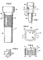
- the cross-section of the threads of part 10 have a shoulder that faces head 10a and is essentially perpendicular to the axis; and the cross-section of the thread has a prominently slanted cam side opposite the thread's shoulder.
- Lines 10d and 10e in Fig. 2 represent the relationship of the thread's shoulder and cam side, respectively, to each other and to the axis of part 10.
- nut 16 is divided into four sectors 16a distributed around the passage which extends through the nut.
- Each sector 16a has a series of thread segments 16b distributed along the axis of the nut; the thread segments 16b of all the sectors 16a collectively form a female thread that mates with the male thread of part 10.
- Each thread segment 16b extends most of the way across its sector 16a.
- Each sector 16a has opposite sides that are adjacent to sides of neighboring sectors 16a.
- the adjacent sides of two successive neighboring sectors 16a are connected to each other by a resilient corrugation 16c.
- each corrugation is U-shaped.
- Each corrugation is resilient, and it is of a form that can flex and expand so as to accommodate forcible displacement of sectors 16a outward, enlarging the passage through the nut.
- the extremities 16f of the corrugations (the junctions of each resilient corrugation with the sides of adjoining sectors 16a) become spread as thread segments 16b ratchet past threads 10c.
- thread segments 16b are complementary to the male thread along portion 10c of part 10. Accordingly, shoulder 16d is approximately perpendicular to the thread's axis, and cam side 16e of the female thread's cross-section slants prominently to the nut's axis. Thread surfaces 16d and 16e in this example do not form a sharp intersection; rather the thread has a blunted edge 16g. A sharp edge would add very little to the thrust resistance provided by the thread's shoulder.
- the illustrative male thread on part 10 has an angle of 45° between its cam side 10e and its shoulder side 10d in this example.
- the same 45° angle (represented by lines 16d′ and 16e′, Figs. 4 and 5) is provided between the shoulder and the slant or cam side of thread segments 16b.
- part 10 is inserted through spacer 14 and panel 12 (or spacer 14 may be omitted) and, while part 10 is held in place, nut 16 is pushed onto part 10.
- nut 16 moves over male threaded portion 10c, the thread segments 16b on each of the sectors 16a ratchet past the male threads.
- sectors 16a are forced outward as cam sides 16e of the nut's thread segments are pushed along cam sides 10e of the male thread.
- the resulting outward spreading of sectors 16a is accommodated by resilient corrugations 16c.
- nut 16 is pressed against panel 10. The nut is then turned to tighten the assembly.
- shoulders 10d and 16d of the threads abut each other.
- Firm tightening is possible because shoulders 10d and 16d do not develop forces tending to spread sectors 16a so long as the tightening force does not distort the material and thereby force the transverse shoulders to tilt.
- the described nut has distinctive properties.
- the stresses (and the reactions) developed at the ends of any thread segment 16b are equal when an effort is made to pull part 10 out of the nut.
- the stresses and strains developed at each of the thread segments are essentially equal. This signifies that all the thread segments contribute alike to the retention of the nut; that none of the thread segments are being over-stressed while others are underutilized.
- the external shape of nut 16 provides for a good grasp.
- a wrench can grip nut 16 at flats 16h, and corrugations 16c provide a good hand grip, when the nut is forcibly turned.
- part 10 is a hollow fuse holder made of a molded plastic part, providing electrical insulation.
- Push nut 16 is also manufactured of a molded plastic. It is easily pushed into place and tightened, and easily unscrewed, yet it is capable of providing enormous resistance against being released unintentionally by random force against part 10. Unlike conventional push nuts of stamped sheet-metal, having spaced-apart teeth to grip a forcibly inserted part, the forces applied by nut 16 to part 10 are distributed almost uniformly, with no appreciable force that night distort tube 10.
- the extent of thread segments 16b along the axis of nut 16 is 6.4 mm; the diameter of nut 16, measured to the thread's root, is 12.7 mm; thread segment 16b (Fig. 5) is 0.117 mm, peak to root, and its pitch is 0.106 mm; thread segments 16b extend around roughly 70% of the nut's inner circumference; corrugation 16c has a groove 0.159 mm deep by 0.119 mm wide and a wall thickness of 0.06 mm at the end and at the sides; and the minimum wall thickness of the nut (halfway between corrugations 16c) is 0.071 mm; all these dimensions being subject to tolerance deviations.
- the push-on force was 1.81 to 2.27 kilograms and the pull-apart force was 27.2 kilograms.
- these values can be varied widely by changes in the kind of plastic used, in the nut's several dimensions, in the number and form of corrugations 16c, and so on.
- the illustrative push nut, as well as the illustrative fastener that includes the male threaded part and the push nut, are subject to many modifications.
- the form of corrugations 16c can be varied, retaining the properties of resilient and flexible connections between adjoining sectors 16a.
Landscapes
- Engineering & Computer Science (AREA)
- General Engineering & Computer Science (AREA)
- Mechanical Engineering (AREA)
- Power Engineering (AREA)
- Dowels (AREA)
- Mutual Connection Of Rods And Tubes (AREA)
Applications Claiming Priority (2)
| Application Number | Priority Date | Filing Date | Title |
|---|---|---|---|
| US07/156,490 US4826379A (en) | 1988-02-16 | 1988-02-16 | Push nuts and push-nut fasteners |
| US156490 | 1988-02-16 |
Publications (2)
| Publication Number | Publication Date |
|---|---|
| EP0329310A2 true EP0329310A2 (de) | 1989-08-23 |
| EP0329310A3 EP0329310A3 (de) | 1990-10-24 |
Family
ID=22559795
Family Applications (1)
| Application Number | Title | Priority Date | Filing Date |
|---|---|---|---|
| EP19890301082 Withdrawn EP0329310A3 (de) | 1988-02-16 | 1989-02-03 | Aufsteckmutter und Befestigungsmittel mit Aufsteckmutter |
Country Status (2)
| Country | Link |
|---|---|
| US (1) | US4826379A (de) |
| EP (1) | EP0329310A3 (de) |
Cited By (1)
| Publication number | Priority date | Publication date | Assignee | Title |
|---|---|---|---|---|
| EP1169536A4 (de) * | 1999-04-05 | 2002-06-12 | Southco | Durch drücken verschliessbarer riegel |
Families Citing this family (24)
| Publication number | Priority date | Publication date | Assignee | Title |
|---|---|---|---|---|
| US4888843A (en) * | 1988-10-27 | 1989-12-26 | Hako Minuteman, Inc. | Holder for rotary pad |
| US5197840A (en) * | 1991-04-03 | 1993-03-30 | Illinois Tool Works Inc. | Insulation retainer |
| US5619770A (en) * | 1995-11-24 | 1997-04-15 | Flo-Pac Corporation | Rotary pad holder with quick-release mechanism |
| EP0932923A1 (de) * | 1996-10-17 | 1999-08-04 | Starpoint Electrics Limited | Befestigungselementen |
| US5899418A (en) * | 1996-11-18 | 1999-05-04 | Thomas & Betts Corporation | Cable fastening device |
| US6196751B1 (en) | 1998-09-11 | 2001-03-06 | Thomas & Betts International, Inc. | Stud mounted fastener for routing wire |
| US6220806B1 (en) | 1999-03-25 | 2001-04-24 | Avaya Technology Corp. | Twin impression push nut |
| EP1052489A3 (de) | 1999-05-12 | 2001-09-05 | Siemens Canada limited | Anordnung zum Befestigen eines Sensors mittels Druck |
| DE10024285A1 (de) * | 2000-05-17 | 2001-11-29 | Christa Reiners | Verbindungsmittel |
| US6719513B1 (en) | 2000-09-19 | 2004-04-13 | Ford Global Technologies, Llc | Reverse bow retention push pin |
| US6520461B1 (en) * | 2001-08-30 | 2003-02-18 | Component Hardware Group, Inc. | Leg support |
| US7052224B2 (en) * | 2001-10-24 | 2006-05-30 | Venus Donald W | Fastener assembly with molded internal helical flutes |
| US6678903B1 (en) * | 2003-01-08 | 2004-01-20 | Masco Corporation Of Indiana | Spray support quick-install nut |
| US7090454B2 (en) * | 2003-07-24 | 2006-08-15 | Floyd Bell, Inc. | Ratchet interlocking housing |
| US20050039551A1 (en) * | 2003-07-24 | 2005-02-24 | Eric Shute | Tamper evident connector for an engine radiator |
| US20060239796A1 (en) * | 2005-04-20 | 2006-10-26 | Franks John R | Cable tie with fir-tree type fastener |
| US20080302425A1 (en) * | 2007-06-05 | 2008-12-11 | Continental Automotive Systems Us, Inc. | Formed Flange For Pressure Monitoring Valve Stem Mount |
| GB2512319B (en) * | 2013-03-26 | 2017-08-30 | Intelligent Energy Ltd | A securing device |
| BR112016018063A2 (pt) * | 2014-02-03 | 2017-08-08 | Lockdowel Inc | Dispositivo de fixação, e, método de fixação de um primeiro substrato em um segundo substrato |
| DE202015009095U1 (de) * | 2015-08-21 | 2016-09-14 | Tesa Se | Haltevorrichtung zur klebenden Befestigung an einer Oberfläche |
| DE102016101910A1 (de) * | 2016-02-03 | 2017-08-03 | Böllhoff Verbindungstechnik GmbH | Kunststoff-Gewindeelement sowie Verbindungsanordnung bestehend aus einem Kunststoffträgerteil und einem Kunststoff-Gewindeelement |
| IL258480B (en) * | 2018-04-01 | 2018-10-31 | Chen Ami | Drill screw and nut |
| US11499585B2 (en) * | 2018-08-09 | 2022-11-15 | Sentient Design, Inc. | Fastener |
| US11873047B2 (en) * | 2020-06-05 | 2024-01-16 | Annex Products Pty Ltd | Vibration dampening device for mounting a handheld electronic device |
Family Cites Families (17)
| Publication number | Priority date | Publication date | Assignee | Title |
|---|---|---|---|---|
| CA651985A (en) * | 1962-11-13 | P. Maxwell William | Fastening device | |
| US1092256A (en) * | 1910-04-09 | 1914-04-07 | Joseph H Glauber | Coupling or lock-nut. |
| US1705811A (en) * | 1927-10-31 | 1929-03-19 | Jr Thomas Edward Eidel | Quick-action lock nut |
| GB1020694A (en) * | 1963-07-25 | 1966-02-23 | Albert Victor Raymond | Improvements in and relating to studs |
| US3342098A (en) * | 1965-08-16 | 1967-09-19 | Tinnerman Products Inc | Sealed expansion fastener |
| DE2010321C3 (de) * | 1970-03-05 | 1973-09-13 | Wieland-Werke Ag, 7900 Ulm | Schraubverbindung bei metallenen Fenster oder Türrahmen |
| GB1334236A (en) * | 1970-03-19 | 1973-10-17 | Itw Ltd | Plastics fasteners |
| ES189653Y (es) * | 1972-03-15 | 1974-10-16 | Un elemento de bloqueo para pasadores guia roscados. | |
| JPS602334Y2 (ja) * | 1980-07-15 | 1985-01-23 | 株式会社ニフコ | ナツト |
| DE3143775C2 (de) * | 1981-11-04 | 1987-01-08 | TRW United-Carr GmbH, 6000 Frankfurt | Vorrichtung zur Befestigung eines mit einer zylindrischen Öffnung versehenen Kunststoffelements, insbesondere Halteteils |
| DE3148043A1 (de) * | 1981-12-04 | 1983-06-09 | Gernold 4800 Bielefeld Jänisch | "duebel- und bolzenanordnung" |
| US4600344A (en) * | 1983-12-05 | 1986-07-15 | Illinois Tool Works Inc. | Push-on plastic wing-nut fastener |
| US4571136A (en) * | 1984-02-10 | 1986-02-18 | Illinois Tool Works Inc. | Plastic push-on fastener |
| ES284830Y (es) * | 1984-02-25 | 1986-05-16 | Raymond A. | Dispositivo de fijacion para pernos roscados, en forma de tuerca |
| DE8405849U1 (de) * | 1984-02-25 | 1984-06-07 | Fa. A. Raymond, 7850 Lörrach | Mutternartiges Befestigungselement für Gewindebolzen |
| US4756654A (en) * | 1984-06-13 | 1988-07-12 | Trw Inc. | Fastening device |
| DE3618486C1 (de) * | 1985-07-19 | 1987-08-06 | United Carr Gmbh Trw | Kunststoffteil zur Halterung eines Gewindebolzens |
-
1988
- 1988-02-16 US US07/156,490 patent/US4826379A/en not_active Expired - Fee Related
-
1989
- 1989-02-03 EP EP19890301082 patent/EP0329310A3/de not_active Withdrawn
Cited By (1)
| Publication number | Priority date | Publication date | Assignee | Title |
|---|---|---|---|---|
| EP1169536A4 (de) * | 1999-04-05 | 2002-06-12 | Southco | Durch drücken verschliessbarer riegel |
Also Published As
| Publication number | Publication date |
|---|---|
| US4826379A (en) | 1989-05-02 |
| EP0329310A3 (de) | 1990-10-24 |
Similar Documents
| Publication | Publication Date | Title |
|---|---|---|
| US4826379A (en) | Push nuts and push-nut fasteners | |
| US4756654A (en) | Fastening device | |
| US10823221B2 (en) | Bonding washer | |
| US4123132A (en) | Screw or nut and a captive washer | |
| US4600344A (en) | Push-on plastic wing-nut fastener | |
| JPS602334Y2 (ja) | ナツト | |
| US4571136A (en) | Plastic push-on fastener | |
| US5791848A (en) | Structure for converting standard drive fastener to security fastener | |
| US5707192A (en) | Panel--fastener connector clip | |
| US4474515A (en) | Expansion fastener | |
| EP0200358A2 (de) | Abdichtende Unterlegscheibe | |
| US4083465A (en) | Retainer clip and synthetic resin box combination | |
| US5868537A (en) | Sponge head retainer pin | |
| US20030180123A1 (en) | System for connecting elements | |
| US6467990B1 (en) | Arrangement for securing a component | |
| CA1258595A (en) | Fastening device | |
| US4379693A (en) | Orthodontic biassing device | |
| EP0024528A2 (de) | Gewindebohrform | |
| US4214667A (en) | Screw mounting mechanism for electrical outlet box | |
| US4416173A (en) | Wrench adapter | |
| DE69902280T2 (de) | Mit gewinde versehenes befestigungselement | |
| US4013110A (en) | Locking thread | |
| JPH06511304A (ja) | ロック部材 | |
| US3039507A (en) | Lock nut having segmented thread structure | |
| US5542799A (en) | Machine screw |
Legal Events
| Date | Code | Title | Description |
|---|---|---|---|
| PUAI | Public reference made under article 153(3) epc to a published international application that has entered the european phase |
Free format text: ORIGINAL CODE: 0009012 |
|
| AK | Designated contracting states |
Kind code of ref document: A2 Designated state(s): CH DE FR GB IT LI |
|
| PUAL | Search report despatched |
Free format text: ORIGINAL CODE: 0009013 |
|
| AK | Designated contracting states |
Kind code of ref document: A3 Designated state(s): CH DE FR GB IT LI |
|
| STAA | Information on the status of an ep patent application or granted ep patent |
Free format text: STATUS: THE APPLICATION IS DEEMED TO BE WITHDRAWN |
|
| 18D | Application deemed to be withdrawn |
Effective date: 19910425 |