EP0329439A2 - Glanzverfahren und -vorrichtung für Schichten - Google Patents
Glanzverfahren und -vorrichtung für Schichten Download PDFInfo
- Publication number
- EP0329439A2 EP0329439A2 EP19890301487 EP89301487A EP0329439A2 EP 0329439 A2 EP0329439 A2 EP 0329439A2 EP 19890301487 EP19890301487 EP 19890301487 EP 89301487 A EP89301487 A EP 89301487A EP 0329439 A2 EP0329439 A2 EP 0329439A2
- Authority
- EP
- European Patent Office
- Prior art keywords
- sheet
- supporting means
- heating elements
- housing
- blower
- Prior art date
- Legal status (The legal status is an assumption and is not a legal conclusion. Google has not performed a legal analysis and makes no representation as to the accuracy of the status listed.)
- Withdrawn
Links
- 238000000034 method Methods 0.000 title claims description 13
- 238000010438 heat treatment Methods 0.000 claims abstract description 31
- 229920005992 thermoplastic resin Polymers 0.000 claims abstract description 28
- 229920005989 resin Polymers 0.000 claims abstract description 17
- 239000011347 resin Substances 0.000 claims abstract description 17
- 238000007664 blowing Methods 0.000 claims description 10
- 230000003134 recirculating effect Effects 0.000 claims description 5
- 230000032258 transport Effects 0.000 description 10
- 229920001169 thermoplastic Polymers 0.000 description 8
- 239000004416 thermosoftening plastic Substances 0.000 description 8
- 238000003384 imaging method Methods 0.000 description 7
- 239000003094 microcapsule Substances 0.000 description 5
- 239000000203 mixture Substances 0.000 description 4
- 239000000758 substrate Substances 0.000 description 4
- 239000000463 material Substances 0.000 description 3
- 238000002844 melting Methods 0.000 description 3
- 230000008018 melting Effects 0.000 description 3
- 238000004581 coalescence Methods 0.000 description 2
- 230000005855 radiation Effects 0.000 description 2
- BQCADISMDOOEFD-UHFFFAOYSA-N Silver Chemical compound [Ag] BQCADISMDOOEFD-UHFFFAOYSA-N 0.000 description 1
- 238000010669 acid-base reaction Methods 0.000 description 1
- 150000001875 compounds Chemical class 0.000 description 1
- 230000003247 decreasing effect Effects 0.000 description 1
- 238000005516 engineering process Methods 0.000 description 1
- 239000002245 particle Substances 0.000 description 1
- 239000000049 pigment Substances 0.000 description 1
- -1 polyethylene terephthalate Polymers 0.000 description 1
- 229920000139 polyethylene terephthalate Polymers 0.000 description 1
- 239000005020 polyethylene terephthalate Substances 0.000 description 1
- 229910052709 silver Inorganic materials 0.000 description 1
- 239000004332 silver Substances 0.000 description 1
Images
Classifications
-
- G—PHYSICS
- G03—PHOTOGRAPHY; CINEMATOGRAPHY; ANALOGOUS TECHNIQUES USING WAVES OTHER THAN OPTICAL WAVES; ELECTROGRAPHY; HOLOGRAPHY
- G03G—ELECTROGRAPHY; ELECTROPHOTOGRAPHY; MAGNETOGRAPHY
- G03G15/00—Apparatus for electrographic processes using a charge pattern
- G03G15/20—Apparatus for electrographic processes using a charge pattern for fixing, e.g. by using heat
-
- G—PHYSICS
- G03—PHOTOGRAPHY; CINEMATOGRAPHY; ANALOGOUS TECHNIQUES USING WAVES OTHER THAN OPTICAL WAVES; ELECTROGRAPHY; HOLOGRAPHY
- G03F—PHOTOMECHANICAL PRODUCTION OF TEXTURED OR PATTERNED SURFACES, e.g. FOR PRINTING, FOR PROCESSING OF SEMICONDUCTOR DEVICES; MATERIALS THEREFOR; ORIGINALS THEREFOR; APPARATUS SPECIALLY ADAPTED THEREFOR
- G03F7/00—Photomechanical, e.g. photolithographic, production of textured or patterned surfaces, e.g. printing surfaces; Materials therefor, e.g. comprising photoresists; Apparatus specially adapted therefor
- G03F7/002—Photomechanical, e.g. photolithographic, production of textured or patterned surfaces, e.g. printing surfaces; Materials therefor, e.g. comprising photoresists; Apparatus specially adapted therefor using materials containing microcapsules; Preparing or processing such materials, e.g. by pressure; Devices or apparatus specially designed therefor
- G03F7/0022—Devices or apparatus
- G03F7/0032—Devices or apparatus characterised by heat providing or glossing means
Definitions
- the present invention relates to a method and apparatus for glossing sheets.
- a coated substrate such as a developer sheet is typically heated in order to provide a glossy finish thereon.
- developer sheets are used in conjunction with conventional pressure-sensitive copy paper or photosensitive imaging systems employing microcapsules to provide visible images upon contact with a colour former which is image-wise released from the microcapsules and transferred to the developer sheet.
- Photosensitive imaging systems employing microencapsulated radiation sensitive compositions are the subject of US-A-4,399,209 and US-A-4,440,846. These imaging systems are characterized in that an imaging sheet including a layer of microcapsules containing a photosensitive composition in the internal phase is image-wise exposed to actinic radiation.
- the photosensitive composition is a photopolymerizable composition including a polyethylenically unsaturated compound and a photoinitiator and is encapsulated with a colour former. Exposure image-wise hardens the internal phase of the microcapsules.
- US-A-4,399,209 discloses a transfer system in which the imaging sheet is assembled with a developer sheet prior to being subjected to a rupturing force. Upon passing through the development station in contact with the developer sheet, the microcapsules rupture and image-wise release the internal phase whereupon the colour former migrates to the developer sheet where it reacts with a dry developer and forms a colour image.
- the imaging system can be designed to reproduce monochromatic or polychromatic full colour images.
- Apparatus for glossing the developer sheets of the foregoing imaging systems are becoming known.
- Our US-A-4,761,311 discloses an apparatus for glossing the developer sheets wherein a developer sheet is fed between the convex side of a heated plate and a continuous belt held snugly against the convex side of the plate; the thermoplastic resin side of the developer sheet is adjacent to the belt.
- U. S. Patent Application Serial No. 016,311, filed February 19, 1987 discloses an apparatus for glossing the developer sheets wherein a developer sheet is fed between a heated belt and a source of radiant energy disposed within a reflector; the thermoplastic resin side of the developer sheet is adjacent to the source of radiant energy.
- Apparatus for glossing developer sheets is disclosed at #27660, Research Disclosure (April 1987) wherein a developer sheet is fed between a heated driven roller and an idler roller. Also, a developer sheet can be glossed by placing in a hot oven.
- thermoplastic resins which are capable of forming a film upon the application of heat, are extremely sticky compared to dry silver film, conventional film, and xerographic copies; thus, the release conditions of the sheet surface are more critical.
- hot roller glossing methods the high contact pressure may cause adhesion of the thermoplastic resin to the hot rollers.
- adhesion of the thermoplastic resin may also be a problem.
- known glossing methods tend not to achieve an even gloss with respect to image density and also tend to be slow. Additionally, the energy requirements of glossing processes are higher than known photographic, glossing, and xerographic toner fusing technologies.
- thermoplastic resins are capable of forming a film which imparts gloss to the sheet upon the application of heat.
- This film is essentially transparent.
- the film imparts a gloss finish when the image is formed on an opaque background and it transmits light efficiently when the image is formed on a transparent background to provide a transparency.
- a glossy film improves perceived image quality by increasing colour saturation.
- the present invention provides in one aspect thereof, an apparatus for glossing a sheet having a thermoplastic resin on the surface thereof, said thermoplastic resin being capable of forming a film which imparts gloss upon the application of heat, characterised in comprising: sheet supporting means; sheet feeding means for feeding a said sheet on to said sheet supporting means with the resin side of said sheet away from said sheet supporting means; heating elements; a blower adapted for blowing air through said heating elements to generate hot air which is blown on to said sheet, said heating elements being located between said blower and said sheet supporting means in the direction of air flow; means for recirculating said hot air; said hot air being blown on to said sheet through openings (an opening) located across the width of said sheet.
- the apparatus of the present invention is advantageous because the thermoplastic resin is not in contact with any surface. Hence, the apparatus of the present invention eliminates the adhesion of the thermoplastic resin on the sheet to another surface.
- thermoplastic resin being capable of forming a film which imparts gloss upon the application of heat
- the method being characterised in comprising the steps of: feeding said sheet to a support station resin side up; blowing air through heating elements and through openings (an opening) located across the width of said sheet on to said sheet at said support station; and recirculating hot air.
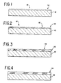
- a glossable developer sheet useful in the practice of the present invention is schematically shown in Fig. 1 wherein the developer sheet is designated generally by the reference numeral 10.
- Particularly useful glossable developer sheets are disclosed in our European Patent Application 87307985.9 (EP-A-0260129); US-A-4,772,532 and US-A-4,554,233.
- the sheet 10 includes a support 12 which is overcoated by a layer 14 of a finely divided thermoplastic developer resin.
- Useful materials for the support 12 include both opaque substrates such as paper and transparent substrates such as a polyethylene terephthalate film. However, preferably, the support 12 is paper.
- a visible image 16 is formed in layer 14 as shown by the cross-hatching in Fig. 2.
- the visible image 16 is usually the product of an acid-base reaction between the colour former, which is usually an electron donor, and the thermoplastic developer resin, which is usually an electron acceptor.
- the developer sheet 10 is subjected to a method in accordance with the present invention to gloss the thermoplastic developer resin on the developer sheet.
- degrees of gloss ranging from matte to low gloss to high gloss can be obtained.
- Fig. 3 schematically illustrates a high gloss finish on the developer sheet 10.
- the thermoplastic developer resin 14 is essentially completely coalesced into a thin, continuous, translucent film.
- An intermediate degree of gloss is schematically shown in Fig. 4 in which partial coalescence of the layer 14 gives a finish which is glossier than the uncoalesced intermediate of Fig. 2 but less glossy than the finish of Fig. 3.
- the support film is transparent and complete coalescence of the developer resin is used.
- Useful developer materials 14 are finely divided reactive thermoplastic pigments which are capable of reacting with a colour former and forming a colour image. Their melting points typically range from about 100 to 200°C, but those skilled in the art will appreciate that materials with higher and lower melting points may also be useful. Preferably, resins have a melting range of about 120 to 130°C are used. The particle size is preferably in the range of about 0.5 to 25 microns.
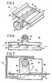
- Fig. 5 illustrates a glossing unit 18 constructed according to the present invention.
- a first set of rollers 20 is used to feed the sheet 22 onto the transport platform 24. Warm rollers can be used to preheat the resin layer so that less energy is required during the hot air step.
- the thermoplastic resin side of the sheet 22 is away from the transport platform 24.
- the transport platform 24 has a slot 26 therein; the slot 26 is a heating fan outlet which extends substantially across the width of the transport platform 24.
- Heating elements 28 are located below the slot 26 in the transport platform 24 to provide heat for glossing.
- useful heating elements 28 operate at a temperature of about 1250° to 1750°C.
- a blower 30 is located beneath the heating elements 28 for blowing air through the heating elements 28 to generate hot air which is uniformly blown onto the sheet 22.
- a useful blower 30 blows about 0.283 to 2.83 m3/min of air onto sheet 28. The light air pressure exerted on the sheet 22 raises the sheet 22 off the transport platform 24; this action ensures even thermal contact because the sheet 22 is then backed by an air gap.
- a second set of cold rollers 32 receives the sheet 22 and ejects the sheet 22 from the glossing unit 18. It should be understood that the distance between the first set of cold rollers 20 and the second set of cold rollers 32 is equal to or less than the length of sheet 22 in order for the rollers to move the sheet over transport platform 24 as shown in Fig. 5.
- Fig. 6 illustrates a second glossing unit 34 also in accordance with the present invention.
- a first set of rollers 36 is used to feed the sheet 38 on to a belt 40. Warm rollers can be used to preheat the resin layer so that less energy is required during the hot air step.
- the belt 40 is placed around roller means.
- the belt 40 transports the sheet 38 through the glossing unit 34.
- the thermoplastic resin side of the sheet 38 is away from the belt 40.
- support means 44 is located beneath belt 40 to provide support for the belt 40 and also for sheets 38 situated on belt 40.
- the support means 44 has a nonconductive surface. Otherwise, if a conductive surface is used, hot spots can occur, and also, the heat would be distributed throughout the glossing unit 34. Heating pads which contact the back surface of support means 44 can be used so as to increase throughput.
- Heating elements 46 are located above belt 40 at the heat application location 42 to provide heat for the glossing. In order to provide sufficient heat for glossing the thermoplastic resin, useful heating elements 46 operate at a temperature of about 1250° to 1750°.
- a blower 48 is located above the heating elements 46 for blowing air through the heating elements 46 to generate hot air which is uniformly blown onto the sheet 38.
- a useful blower 48 blows about 0.283 to 2.83 m3/min of air onto sheet 38.
- the sheet 38 has been heated prior to entering the glossing unit 34 so that the sheet 38 will not act as a heat sink with respect to the hot air blown onto sheet 38.
- a vertical baffle 50 is situated near the heating elements 46 so that the hot air is directed in a narrow cross section across the width of the sheet 38 as indicated by the arrow.
- the air is circulated back through the blower 48 as indicated by the arrow. As a result of the air recirculation, the energy requirements of the glossing unit 34 are decreased.
- a second set of cold rollers 52 receives the sheet 38 and ejects the sheet 38 from the glossing unit 34.
- Fig. 7 illustrates a further glossing unit also in accordance with the present invention.
- a first set of rollers 56 is used to feed the sheet 58 into the glossing unit 54. Again, warm rollers can be used to preheat the resin so that less energy is required during the hot air step.
- the thermoplastic resin side of the sheet 58 is away from the sheet supporting means.
- a means is located above the sheet supporting means for blowing hot air onto the sheet 58.
- the means comprises a housing 60 having heating elements 62 located therein to provide heat for the glossing.
- useful heating elements 62 operate at a temperature of about 1250° to 1750°C.
- a blower 64 is located in the housing 60 for blowing air through the heating elements 62 to generate hot air which is uniformly blown onto sheet 58 through an opening which extends across the width of sheet 58 as indicated by the arrow.
- a useful blower 64 blows about 0.283 to 2.83 m3/min of air onto sheet 58.
- a vertical baffle 66 is situated near the heating elements 62 so that the hot air is directed onto the sheet 58 through an opening which extends across the width of sheet 58 as indicated by the arrow. A portion of the hot air passes beneath the baffle 66 and over the baffle 67, and is circulated back through the blower 64 as indicated by the arrow.
- the horizontal baffle 67 helps to prevent fluttering, due to the air flow, of the sheet 58 as it passes through glossing unit 54.
- Vacuum means 68 is located below the belt 56 for sucking in the hot air.
- the application of the vacuum as shown by the multiple arrows helps to ensure that the sheet 58 does not flutter due to the air application as the sheet 58 passes over the horizontal upper surface of vacuum means 68.
- the glossing unit 54 also includes air recirculation means 70.
- the air recirculation means 70 comprises a pipe which runs from the vacuum means 68 to the housing 60; the air flows as shown by the arrow through air recirculation means 70 and back through blower 64.
- the air recirculation means 70 is positioned so that it does not interfere with the feeding of sheets 58 into the glossing unit 54.
- a second set of cold rollers 72 receives the sheet 58 and ejects the sheet 58 from the glossing unit 54. It should be understood that the distance between the first set of cold rollers 56 and the second set of cold rollers 72 is equal to or less than the length of sheet 58 in order for the rollers to move the sheet over vacuum means 68.
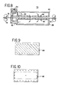
- Fig. 8 illustrates a further embodiment of glossing unit 74 in accordance with the present invention.
- a first set of rollers 76 is used to feed the sheet 78 into the glossing unit 74. Again, warm rollers can be used.
- the thermoplastic resin side of the sheet 78 is away from the sheet supporting means.
- a manifold is located above the sheet supporting means for blowing hot air onto the sheet 78.
- An air gap exists between the bottom of the manifold and the thermoplastic resin side of the sheet 78.
- the manifold comprises a housing 80 having heating elements 82 located therein to provide heat for the glossing. In order to provide sufficient heat for glossing the thermoplastic resin, useful heating elements 82 operate at a temperature of about 1250° to 2750°C.
- a blower 84 is located in the housing 80 for blowing air as shown by the arrow through the heating elements 82 to generate hot air which is uniformly blown onto the entire surface of sheet 78.
- a useful blower 84 blows about 0.283 to 2. 83m3/min of air onto the entire surface of the sheet 78.
- the housing 80 is a pressure manifold.
- the lower surface 86 of the pressure manifold has a plurality of holes therein in a regular pattern.
- regular as used herein means that the distances between holes are regular or constant.
- a particularly useful regular pattern of holes is the pattern shown in Fig. 9.
- Vacuum means 88 for sucking in the hot air is located below housing 80.
- the vacuum means 88 is a vacuum manifold. The application of the vacuum as shown by the multiple arrows helps to ensure that the sheet 78 does not flutter due to the air application as it passes over the horizontal upper surface 90 of vacuum means 88.
- the upper surface 90 of the vacuum manifold has a plurality of holes therein.
- the innermost section which is outlined by dotted lines, corresponds to the area of the sheet 78 for holding the sheet 78 down; the perimeter section has holes in a regular pattern for passage of the hot air therethrough.
- the glossing unit 74 also includes air recirculation means 92.
- the air recirculation means 92 comprises a pipe which runs from the vacuum manifold to the pressure manifold; the air flows as shown by the arrow through air recirculation means 92 and back through blower 84.
- the air recirculation means 92 is positioned so that it does not interfere with the feeding of sheets 78 into the glossing unit 74.
- the energy requirements of the glossing unit 74 are less than other units.
- a second set of cold rollers 94 receives the sheet 78 and ejects the sheet 78 from the glossing unit 74. It should be understood that the distance between the first set of cold rollers 76 and the second set of cold rollers 94 is equal to or less than the length of sheet 78 in order for the rollers to move the sheet over the vacuum manifold.
Landscapes
- Physics & Mathematics (AREA)
- General Physics & Mathematics (AREA)
- Laminated Bodies (AREA)
- Fixing For Electrophotography (AREA)
- Color Printing (AREA)
- Shaping Of Tube Ends By Bending Or Straightening (AREA)
Applications Claiming Priority (2)
| Application Number | Priority Date | Filing Date | Title |
|---|---|---|---|
| US07/155,795 US5086209A (en) | 1988-02-16 | 1988-02-16 | Hot air apparatus for glossing sheets |
| US155795 | 1988-02-16 |
Publications (2)
| Publication Number | Publication Date |
|---|---|
| EP0329439A2 true EP0329439A2 (de) | 1989-08-23 |
| EP0329439A3 EP0329439A3 (de) | 1990-11-22 |
Family
ID=22556826
Family Applications (1)
| Application Number | Title | Priority Date | Filing Date |
|---|---|---|---|
| EP19890301487 Withdrawn EP0329439A3 (de) | 1988-02-16 | 1989-02-16 | Glanzverfahren und -vorrichtung für Schichten |
Country Status (5)
| Country | Link |
|---|---|
| US (1) | US5086209A (de) |
| EP (1) | EP0329439A3 (de) |
| JP (1) | JP2643416B2 (de) |
| KR (1) | KR900013356A (de) |
| CN (1) | CN1039315A (de) |
Cited By (2)
| Publication number | Priority date | Publication date | Assignee | Title |
|---|---|---|---|---|
| EP0353105A3 (de) * | 1988-07-29 | 1990-11-14 | Brother Kogyo Kabushiki Kaisha | Bildaufzeichnungs-Vorrichtung |
| EP1248162A3 (de) * | 2001-04-06 | 2006-03-01 | Eastman Kodak Company | Vorheizeinheit für eine Fixierbaugruppe einer elektrostatischen Reproduktionsvorrichtung |
Families Citing this family (18)
| Publication number | Priority date | Publication date | Assignee | Title |
|---|---|---|---|---|
| US5634167A (en) * | 1995-10-26 | 1997-05-27 | Xerox Corporation | Constrained film heat processor and method of developing digital film using radiant heat transfer |
| US5669032A (en) * | 1995-10-27 | 1997-09-16 | Xerox Corporation | Constrained film heat processor and method of developing digital film using conduction heat transfer |
| US6523949B1 (en) * | 1999-03-09 | 2003-02-25 | Brian C. Ewert | Variable image printing using inkjet printer |
| IT1310555B1 (it) * | 1999-04-02 | 2002-02-18 | Gisulfo Baccini | Apparecchiatura per la produzione di circuiti elettronici |
| US6167220A (en) * | 1999-11-05 | 2000-12-26 | Xerox Corporation | Anti-condensation baffle unit |
| JP2001154510A (ja) * | 1999-11-26 | 2001-06-08 | Fuji Xerox Co Ltd | 転写定着装置、像担持搬送体及び画像形成装置 |
| US6226474B1 (en) * | 1999-12-16 | 2001-05-01 | Nexpress Solutions Llc | Air impingement post fuser receiver member cooler device |
| US6503055B1 (en) * | 2000-10-30 | 2003-01-07 | Heidelberger Druckmaschinen Ag | Environmental control system blower assembly |
| JP4785466B2 (ja) * | 2005-08-30 | 2011-10-05 | 京セラミタ株式会社 | 画像形成装置 |
| US20070098963A1 (en) * | 2005-10-27 | 2007-05-03 | Xiaoqi Zhou | Toner receiving compositions for electrophotographic toner receiving systems |
| JP2007248679A (ja) * | 2006-03-15 | 2007-09-27 | Konica Minolta Business Technologies Inc | 画像形成装置 |
| US20070237910A1 (en) * | 2006-04-07 | 2007-10-11 | Xiaoqi Zhou | Media sheet |
| US7807256B2 (en) * | 2007-01-30 | 2010-10-05 | Hewlett-Packard Development Company, L.P. | Toner receiving composition |
| US7505722B2 (en) * | 2007-02-08 | 2009-03-17 | Xerox Corporation | Convective hot air impingement device with localized return paths |
| JP5028672B2 (ja) * | 2007-05-23 | 2012-09-19 | ボイス パテント ゲーエムベーハー | 古紙裁断用ロータ |
| DE102007048158B3 (de) * | 2007-10-08 | 2009-05-20 | OCé PRINTING SYSTEMS GMBH | Kühleinrichtung und Kühlverfahren für einen Bedruckstoff bei einem elektrografischen Druck- oder Kopiergerät |
| WO2017010123A1 (ja) * | 2015-07-14 | 2017-01-19 | ローター工業株式会社 | パルパーおよびパルパーロータの刃部構造 |
| JP7139979B2 (ja) * | 2019-01-31 | 2022-09-21 | 富士フイルムビジネスイノベーション株式会社 | 定着装置、画像形成装置 |
Family Cites Families (14)
| Publication number | Priority date | Publication date | Assignee | Title |
|---|---|---|---|---|
| US3219799A (en) * | 1963-02-07 | 1965-11-23 | Xerox Corp | Xerographic fusing apparatus |
| NL6501481A (de) * | 1964-02-15 | 1965-08-16 | ||
| US3492458A (en) * | 1967-10-30 | 1970-01-27 | Eastman Kodak Co | Thermofusing device |
| DE6805585U (de) * | 1967-11-14 | 1969-04-17 | Minolta Camera Kk | Vorrichtung zum trocknen und fixieren in einem elektrophotographischen kopiergeraet |
| US3628860A (en) * | 1968-01-31 | 1971-12-21 | Minoltacamera Kk | Heat-fusing apparatus in electrostatic copier |
| US3498592A (en) * | 1968-05-24 | 1970-03-03 | Xerox Corp | Heat fixing apparatus for fusible material |
| US3517164A (en) * | 1968-07-22 | 1970-06-23 | Addressograph Multigraph | Image fusing assembly |
| AU480768B2 (en) * | 1972-05-19 | 1977-02-10 | Canon Kabushiki Kaisha | Device for drying and fixing a copying material |
| US4015103A (en) * | 1975-02-19 | 1977-03-29 | Xerox Corporation | Fuser conveyor belt |
| US4155294A (en) * | 1977-10-25 | 1979-05-22 | Rotofry Systems, Inc. | Cooking apparatus for foodstuffs |
| US4160595A (en) * | 1978-06-27 | 1979-07-10 | Copyer Co., Ltd. | Copying machine equipped with a flash type fixing apparatus |
| JPS56156897U (de) * | 1980-04-23 | 1981-11-24 | ||
| JPS5792359A (en) * | 1980-11-28 | 1982-06-08 | Ricoh Co Ltd | Vapored-solvent collector of wet electronic copying machine |
| US4554235A (en) * | 1984-05-17 | 1985-11-19 | The Mead Corporation | Microencapsulated transfer imaging system employing developer sheet and discontinuous layer of thermoplastic pigment |
-
1988
- 1988-02-16 US US07/155,795 patent/US5086209A/en not_active Expired - Fee Related
-
1989
- 1989-02-14 KR KR1019890001668A patent/KR900013356A/ko not_active Withdrawn
- 1989-02-16 EP EP19890301487 patent/EP0329439A3/de not_active Withdrawn
- 1989-02-16 JP JP1037313A patent/JP2643416B2/ja not_active Expired - Fee Related
- 1989-02-16 CN CN89100819A patent/CN1039315A/zh active Pending
Cited By (4)
| Publication number | Priority date | Publication date | Assignee | Title |
|---|---|---|---|---|
| EP0353105A3 (de) * | 1988-07-29 | 1990-11-14 | Brother Kogyo Kabushiki Kaisha | Bildaufzeichnungs-Vorrichtung |
| US5126781A (en) * | 1988-07-29 | 1992-06-30 | Brother Kogyo Kabushiki Kaisha | Image recording apparatus |
| EP1248162A3 (de) * | 2001-04-06 | 2006-03-01 | Eastman Kodak Company | Vorheizeinheit für eine Fixierbaugruppe einer elektrostatischen Reproduktionsvorrichtung |
| DE10211867B4 (de) * | 2001-04-06 | 2014-12-18 | Eastman Kodak Co. | Fixierbaugruppe mit Vorheizeinheit für eine elektrostatische Reproduktionsvorrichtung |
Also Published As
| Publication number | Publication date |
|---|---|
| EP0329439A3 (de) | 1990-11-22 |
| CN1039315A (zh) | 1990-01-31 |
| JPH02147241A (ja) | 1990-06-06 |
| JP2643416B2 (ja) | 1997-08-20 |
| US5086209A (en) | 1992-02-04 |
| KR900013356A (ko) | 1990-09-05 |
Similar Documents
| Publication | Publication Date | Title |
|---|---|---|
| US5086209A (en) | Hot air apparatus for glossing sheets | |
| US4737822A (en) | Image recording apparatus and method | |
| US4659927A (en) | Image transfer apparatus and method | |
| JP4040329B2 (ja) | 静電写真式複写装置における融着アセンブリのための予熱ヒータ、ならびに、このような予熱ヒータを備えた融着アセンブリ | |
| US5004891A (en) | Two-stage method and apparatus for glossing a developer sheet | |
| EP0320973B1 (de) | Glanzmaschine für Bilder | |
| US5441838A (en) | Simulated gloss process | |
| US3826892A (en) | Fusing apparatus | |
| US5235393A (en) | Toner image-fixing apparatus having air cooling device | |
| JPH0325481A (ja) | 定着装置及び定着用フィルム | |
| US5126781A (en) | Image recording apparatus | |
| US4761311A (en) | Process for glossing a developer sheet and an apparatus useful therein | |
| GB2198253A (en) | Image forming process and system including heating step or device for increased density of images | |
| GB2201803A (en) | Photosensitive recording system | |
| US3907492A (en) | Fusing apparatus | |
| US4825251A (en) | Imaging process involving hardening of imaging web border area photosensitive microcapsules and an apparatus useful therein | |
| EP0864944A1 (de) | Thermische Entwicklungsvorrichtung | |
| US4806733A (en) | Radiant glossing apparatus for glossing developer sheets and a process for using the same | |
| US4940643A (en) | Recording system having a coating device for coating recording medium or photosensitive medium with developer material reacting with color precursor | |
| JPH09171311A (ja) | 画像形成装置 | |
| US5357326A (en) | High quality color highlight prints using B/W xerography | |
| JP2004205748A (ja) | 定着装置 | |
| JPH02301759A (ja) | 画像光沢化装置を備える画像形成装置 | |
| US4807560A (en) | Apparatus for glossing a developer sheet | |
| USRE28802E (en) | Fusing apparatus |
Legal Events
| Date | Code | Title | Description |
|---|---|---|---|
| PUAI | Public reference made under article 153(3) epc to a published international application that has entered the european phase |
Free format text: ORIGINAL CODE: 0009012 |
|
| AK | Designated contracting states |
Kind code of ref document: A2 Designated state(s): DE FR GB |
|
| PUAL | Search report despatched |
Free format text: ORIGINAL CODE: 0009013 |
|
| AK | Designated contracting states |
Kind code of ref document: A3 Designated state(s): DE FR GB |
|
| RIN1 | Information on inventor provided before grant (corrected) |
Inventor name: KINTZ, KARL A. Inventor name: MESSER, RUSSELL KENNETH II Inventor name: NELSON, ERIK K. Inventor name: MCCRARY, CARL W. |
|
| STAA | Information on the status of an ep patent application or granted ep patent |
Free format text: STATUS: THE APPLICATION IS DEEMED TO BE WITHDRAWN |
|
| 18D | Application deemed to be withdrawn |
Effective date: 19910523 |