EP0329516A1 - Vorrichtungen zum Anschluss eines Schrägseiles an eine Brückenfahrbahn aus Beton und damit ausgestattete Brücke - Google Patents
Vorrichtungen zum Anschluss eines Schrägseiles an eine Brückenfahrbahn aus Beton und damit ausgestattete Brücke Download PDFInfo
- Publication number
- EP0329516A1 EP0329516A1 EP19890400311 EP89400311A EP0329516A1 EP 0329516 A1 EP0329516 A1 EP 0329516A1 EP 19890400311 EP19890400311 EP 19890400311 EP 89400311 A EP89400311 A EP 89400311A EP 0329516 A1 EP0329516 A1 EP 0329516A1
- Authority
- EP
- European Patent Office
- Prior art keywords
- deck
- plate
- stay
- cables
- flat
- Prior art date
- Legal status (The legal status is an assumption and is not a legal conclusion. Google has not performed a legal analysis and makes no representation as to the accuracy of the status listed.)
- Granted
Links
- 239000004567 concrete Substances 0.000 title claims abstract description 5
- 239000002184 metal Substances 0.000 claims abstract description 3
- 230000000149 penetrating effect Effects 0.000 claims description 2
- 238000004873 anchoring Methods 0.000 abstract description 4
- 230000000717 retained effect Effects 0.000 abstract 1
- 238000010276 construction Methods 0.000 description 2
- 235000000396 iron Nutrition 0.000 description 2
- 230000002787 reinforcement Effects 0.000 description 2
- 230000003247 decreasing effect Effects 0.000 description 1
- 238000004519 manufacturing process Methods 0.000 description 1
- 238000000034 method Methods 0.000 description 1
- 238000012986 modification Methods 0.000 description 1
- 230000004048 modification Effects 0.000 description 1
- 238000009417 prefabrication Methods 0.000 description 1
- 239000011150 reinforced concrete Substances 0.000 description 1
Images


Classifications
-
- E—FIXED CONSTRUCTIONS
- E01—CONSTRUCTION OF ROADS, RAILWAYS, OR BRIDGES
- E01D—CONSTRUCTION OF BRIDGES, ELEVATED ROADWAYS OR VIADUCTS; ASSEMBLY OF BRIDGES
- E01D19/00—Structural or constructional details of bridges
- E01D19/14—Towers; Anchors ; Connection of cables to bridge parts; Saddle supports
Definitions
- the present invention relates to a device for attaching a stay cable to a concrete deck of a bridge, in particular a so-called "fan-shaped" cable-stayed bridge, in which a series of stay cables connects regularly spaced points. of the deck at the top of a support pylon.
- the fixing of a shroud to the deck is done by providing that the shroud crosses the deck, generally at the level of a longitudinal member, to come to carry, on the opposite face of the deck, retaining means for ends, which bear on this underside of the deck.
- the object of the present invention is to remedy this drawback, and to provide a fastening device which does not require modification of the reinforcement planes at the level of each fastening of the stay cable, and consequently allows a faster and less prone construction. at risk of errors.
- the invention provides a device for hanging a stay cable on a concrete deck of a bridge, which comprises: - A metal plate, one face of which is designed to come against a flat support surface of the apron, this face carrying at least one projection capable of penetrating into a cavity of the apron to prevent relative sliding of the plate and of said flat surface d 'support, means for hooking the end of the stay, these means being carried by fittings integral with the face of the plate opposite to that which is designed to come into abutment against the deck, and - prestressing cables or tie rods, capable of holding the plate in abutment against the flat surface of the deck, these cables or tie rods bearing on the side of the deck opposite to that which carries said flat surface.
- the protrusion and / or the cavity have a shape of revolution around an axis perpendicular to the plane of the plate of the planar support surface, to allow the orientation of the device as a function of the direction of the shroud.
- the projection contains the means for retaining one of said cables or prestressing tie rods.
- the attachment means are provided to allow the stay to be maintained with a non-zero inclination relative to the plate.
- said flat bearing surface of the deck is a horizontal surface, and that the cables or tie rods of prestressing cross the deck down to come to bear on a horizontal surface directed in the direction opposite of said apron.
- the anchoring means are provided to allow the stay to be held in a plane parallel to that of the plate.
- This second modality is particularly advantageous if it is provided that the flat bearing surface of the deck is carried by one of the edges of the deck, and has with the vertical the same angle as the sheet of which the shroud which the device must maintain , and the cable or prestressing tie crosses the deck in a transverse direction and approximately horizontal as a whole.
- the invention also provides a cable-stayed bridge equipped with devices as described above, and which has the particularity that the deck carries, at regular intervals, flat bearing surfaces, oriented parallel to each other, and these flat surfaces support supports hooking devices that hold cables with different directions from one to the other.
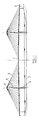
- Figure 1 shows a bridge, whose deck 1 rests at one end on abutments 2, and is supported by guy lines 3, which connect successive points of the deck with the top 4 of pylon 5 mounted on piers 6, which rest on the ground 7.
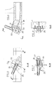
- FIG. 2 a hooking device according to the invention is seen mounted on the upper, horizontal face of an apron 1.
- the device comprises a plate 10, which carries at its lower part a frustoconical projection 11, which penetrates into a corresponding cavity of the upper face of the deck 1.
- a plate 10 which carries at its lower part a frustoconical projection 11, which penetrates into a corresponding cavity of the upper face of the deck 1.
- irons 12, 13, with cross-section T are fixed obliquely on said plate 11, their general direction making with the horizontal an angle equal to that of the shroud 3 that the device is intended to retain.
- a hooking piece 14, welded to the irons 12 and 13, is crossed by the end of the stay 3, which bears on this piece 14 via a terminal piece 15.
- Prestressing tie rods 16 pass through the whole 'thickness of the apron 11, and, thanks to screws 17, 18, strongly tighten the plate 10 against the apron.
- the tensile forces exerted by the shroud 3 can be broken down into a vertical component, which is taken up by the tie rods 16, and a horizontal component, which is transmitted to the deck by the projection 11 and by the friction of the plate 10 against the surface.
- horizontal support provided on the deck.
- FIGS 5 to 8 show another embodiment.
- the deck has, on its outer edge, or shore, a bearing surface 20, oriented longitudinally, and a little oblique with respect to the vertical.
- the bearing surface 20 is, on the whole, circular.
- the deck 1 being relatively thin, it has an extra thickness 21 to receive this bearing surface.
- the attachment device proper comprises a plate 22, of circular shape, which comes to bear on the surface 20, and carries, in its part facing the deck, a frustoconical projection 23 which is hollow and is housed in a cavity also frusto-conical 24 provided in the center of the bearing surface 20.
- the plate 22 On its face opposite to the projection 23, the plate 22 carries fittings constituted by two flat bars 25, identical, arranged perpendicular to the plate 20, and forming between them a sort of yoke, between which is housed a support piece 26, against which carries an end piece 27 integral with the shroud 3.
- the hollow projection 23 serves as a housing for the anchoring head of a prestressing cable 28, which penetrates inside the deck 1 by an oblique passage, perpendicular to the plane of the surface 20. This cable then bends to become horizontal and crosses the entire width of the deck, to be anchored on a similar device located on the oppo shore the apron.
- the device to set up the shrouds, the device must be oriented by pivoting the plate around the axis of the cavity 24, until it is brought in the right direction.
- the inclination of the surfaces 20 relative to the horizontal is that of all the shrouds of the same layer of cables which support the edge of the deck. It is therefore sufficient, during the construction of the bridge, to provide on the deck support surfaces 20 identical to each other, at the locations provided, and to orient each time the plate 22 to obtain perfect alignment of the hanging device with cables.
Landscapes
- Engineering & Computer Science (AREA)
- Architecture (AREA)
- Civil Engineering (AREA)
- Structural Engineering (AREA)
- Bridges Or Land Bridges (AREA)
- Installation Of Indoor Wiring (AREA)
- Road Signs Or Road Markings (AREA)
Priority Applications (1)
| Application Number | Priority Date | Filing Date | Title |
|---|---|---|---|
| AT89400311T ATE73186T1 (de) | 1988-02-05 | 1989-02-03 | Vorrichtungen zum anschluss eines schraegseiles an eine brueckenfahrbahn aus beton und damit ausgestattete bruecke. |
Applications Claiming Priority (2)
| Application Number | Priority Date | Filing Date | Title |
|---|---|---|---|
| FR8801343 | 1988-02-05 | ||
| FR8801343A FR2626910B1 (fr) | 1988-02-05 | 1988-02-05 | Dispositif d'accrochage d'un hauban sur un tablier en beton d'un pont, et pont equipe de tels dispositifs |
Publications (2)
| Publication Number | Publication Date |
|---|---|
| EP0329516A1 true EP0329516A1 (de) | 1989-08-23 |
| EP0329516B1 EP0329516B1 (de) | 1992-03-04 |
Family
ID=9362967
Family Applications (1)
| Application Number | Title | Priority Date | Filing Date |
|---|---|---|---|
| EP89400311A Expired - Lifetime EP0329516B1 (de) | 1988-02-05 | 1989-02-03 | Vorrichtungen zum Anschluss eines Schrägseiles an eine Brückenfahrbahn aus Beton und damit ausgestattete Brücke |
Country Status (9)
| Country | Link |
|---|---|
| US (1) | US5088142A (de) |
| EP (1) | EP0329516B1 (de) |
| JP (1) | JPH02503100A (de) |
| AT (1) | ATE73186T1 (de) |
| DE (1) | DE68900887D1 (de) |
| ES (1) | ES2030278T3 (de) |
| FR (1) | FR2626910B1 (de) |
| GR (1) | GR3003968T3 (de) |
| WO (1) | WO1989007174A1 (de) |
Families Citing this family (3)
| Publication number | Priority date | Publication date | Assignee | Title |
|---|---|---|---|---|
| US7101928B1 (en) * | 1999-09-17 | 2006-09-05 | Landec Corporation | Polymeric thickeners for oil-containing compositions |
| KR20030000063A (ko) * | 2001-06-22 | 2003-01-06 | 대림산업 주식회사 | 전단 마찰저항이 증가된 부착형 정착구 및 이의 설치방법 |
| CN104264584B (zh) * | 2014-10-14 | 2017-01-18 | 中铁二院工程集团有限责任公司 | 预应力混凝土斜拉桥梁顶组合式索梁锚固结构 |
Citations (2)
| Publication number | Priority date | Publication date | Assignee | Title |
|---|---|---|---|---|
| US3953980A (en) * | 1975-01-13 | 1976-05-04 | Floyd William Bennett | Dock structure |
| EP0288350A1 (de) * | 1987-03-27 | 1988-10-26 | Societe Centrale D'etudes Et De Realisations Routieres- Scetauroute | Brücke, bestehend aus einem Deck und dessen Trägern, insbesondere Schrägseilbrücke und Verfahren zu ihrer Herstellung |
Family Cites Families (6)
| Publication number | Priority date | Publication date | Assignee | Title |
|---|---|---|---|---|
| US3414924A (en) * | 1966-11-21 | 1968-12-10 | Bethlehem Steel Corp | Bridge suspender collar |
| US3491393A (en) * | 1967-10-18 | 1970-01-27 | Bethlehem Steel Corp | Suspension bridge cable construction and support assembly |
| DE3434620A1 (de) * | 1984-09-21 | 1986-04-03 | Dyckerhoff & Widmann AG, 8000 München | Abstuetzung eines freien zugglieds, vorzugsweise eines schraegseils einer schraegseilbruecke |
| FR2592666B1 (fr) * | 1986-01-07 | 1988-03-11 | Sogelerg | Systeme de sustentation par cable souple a encastrement local, notamment pour pont a haubans |
| FR2629111B1 (fr) * | 1988-03-25 | 1990-11-30 | Muller Jean | Tablier pour pont de grande longueur |
| FR2632805B1 (fr) * | 1988-06-08 | 1990-08-24 | Bull Sa | Plaque de masquage de carte de circuits imprimes equipee et son procede de fabrication |
-
1988
- 1988-02-05 FR FR8801343A patent/FR2626910B1/fr not_active Expired - Lifetime
-
1989
- 1989-02-03 EP EP89400311A patent/EP0329516B1/de not_active Expired - Lifetime
- 1989-02-03 US US07/425,201 patent/US5088142A/en not_active Expired - Fee Related
- 1989-02-03 ES ES198989400311T patent/ES2030278T3/es not_active Expired - Lifetime
- 1989-02-03 DE DE8989400311T patent/DE68900887D1/de not_active Expired - Fee Related
- 1989-02-03 WO PCT/FR1989/000041 patent/WO1989007174A1/fr not_active Ceased
- 1989-02-03 AT AT89400311T patent/ATE73186T1/de active
- 1989-02-03 JP JP1502103A patent/JPH02503100A/ja active Pending
-
1992
- 1992-03-05 GR GR910401865T patent/GR3003968T3/el unknown
Patent Citations (2)
| Publication number | Priority date | Publication date | Assignee | Title |
|---|---|---|---|---|
| US3953980A (en) * | 1975-01-13 | 1976-05-04 | Floyd William Bennett | Dock structure |
| EP0288350A1 (de) * | 1987-03-27 | 1988-10-26 | Societe Centrale D'etudes Et De Realisations Routieres- Scetauroute | Brücke, bestehend aus einem Deck und dessen Trägern, insbesondere Schrägseilbrücke und Verfahren zu ihrer Herstellung |
Also Published As
| Publication number | Publication date |
|---|---|
| GR3003968T3 (de) | 1993-03-16 |
| DE68900887D1 (de) | 1992-04-09 |
| JPH02503100A (ja) | 1990-09-27 |
| ATE73186T1 (de) | 1992-03-15 |
| EP0329516B1 (de) | 1992-03-04 |
| FR2626910A1 (fr) | 1989-08-11 |
| WO1989007174A1 (fr) | 1989-08-10 |
| US5088142A (en) | 1992-02-18 |
| ES2030278T3 (es) | 1992-10-16 |
| FR2626910B1 (fr) | 1990-06-29 |
Similar Documents
| Publication | Publication Date | Title |
|---|---|---|
| EP0802145A1 (de) | Hebebalken | |
| FR2634909A1 (fr) | Lunette comportant des moyens de fixation rapide des branches et du repose-nez | |
| FR2757602A1 (fr) | Assise de cables et procede de pose de cables | |
| EP0329516B1 (de) | Vorrichtungen zum Anschluss eines Schrägseiles an eine Brückenfahrbahn aus Beton und damit ausgestattete Brücke | |
| FR2860013A1 (fr) | Pont destine a franchir notamment une passe d'une voie de navigation | |
| EP0152367B1 (de) | Vorrichtung zum Herstellen von Fugen, im allgemeinen in Industriefussböden aus Beton | |
| FR2744786A1 (fr) | Assemblage de poutrelles comportant des liaisons directes entre poutrelles | |
| EP0282385B1 (de) | Vorrichtung zur Verankerung an Dachsparren bei Dacharbeiten | |
| EP1010843B1 (de) | Stützfussvorrichtung für Stange oder Pfosten, insbesondere für Laube- oder Paneelunterstützung und Schliessverfahren dafür | |
| EP0594475B1 (de) | Ausstellschere für Kippfenster | |
| EP0282416B1 (de) | Schrämmaschine mit einem beweglich auf einer gewölbt gebogenen und zu ihrer Achse schrägen Führung montierten Schrämmkopf | |
| EP3985190A1 (de) | Vorrichtung zum befestigen eines pfostens | |
| FR2656016A1 (fr) | Dispositif de stabilisation du tablier d'un pont par rapport a ses piles. | |
| FR2728002A1 (fr) | Structure de garde-corps | |
| EP1418283A1 (de) | Modulare Trägerstruktur | |
| FR2787481A1 (fr) | Dispositif formant pied pour piquet ou mat, notamment pour pied de tonnelle ou panneau, et son procede de fermeture | |
| FR2806429A1 (fr) | Procede pour renforcer un cable porteur de structure suspendue de genie civil et structure de genie civil comportant un cable porteur renforce | |
| FR2749871A1 (fr) | Element de plancher pour echafaudage | |
| FR2778213A1 (fr) | Ensemble destine a la realisation d'une bride, bride comprenant cet ensemble et construction comprenant un mat associe a au moins une hampe par cette bride | |
| FR2671574A1 (fr) | Etrier d'echafaudage suspendu et module d'echafaudage comportant ledit etrier. | |
| EP1647648B1 (de) | Verbindungsvorrichtung zwischen einem Eckpfosten und zwei Füllelementen in einem Geländer | |
| FR2731031A1 (fr) | Procede d'installation d'un dispositif a main courante, notamment d'une cloture, et dispositif pour la mise en oeuvre du procede | |
| FR2733776A1 (fr) | Porte de barrage a surverse | |
| FR2598736A1 (fr) | Organe de fixation d'un element de couverture a ses liteaux et element de couverture amenage pour recevoir ledit organe. | |
| FR2798152A1 (fr) | Dispositif auxiliaire pour renforcer le maintien des dalles d'un parement de mur |
Legal Events
| Date | Code | Title | Description |
|---|---|---|---|
| PUAI | Public reference made under article 153(3) epc to a published international application that has entered the european phase |
Free format text: ORIGINAL CODE: 0009012 |
|
| AK | Designated contracting states |
Kind code of ref document: A1 Designated state(s): AT BE CH DE ES FR GB GR IT LI LU NL SE |
|
| 17P | Request for examination filed |
Effective date: 19900201 |
|
| 17Q | First examination report despatched |
Effective date: 19910708 |
|
| DIN1 | Information on inventor provided before grant (deleted) | ||
| RAP1 | Party data changed (applicant data changed or rights of an application transferred) |
Owner name: SOCIETE CENTRALE D'ETUDES ET DE REALISATIONS ROUTI |
|
| RIN1 | Information on inventor provided before grant (corrected) |
Inventor name: MULLER, JEAN |
|
| GRAA | (expected) grant |
Free format text: ORIGINAL CODE: 0009210 |
|
| AK | Designated contracting states |
Kind code of ref document: B1 Designated state(s): AT BE CH DE ES FR GB GR IT LI LU NL SE |
|
| PG25 | Lapsed in a contracting state [announced via postgrant information from national office to epo] |
Ref country code: NL Effective date: 19920304 Ref country code: AT Effective date: 19920304 |
|
| REF | Corresponds to: |
Ref document number: 73186 Country of ref document: AT Date of ref document: 19920315 Kind code of ref document: T |
|
| GBT | Gb: translation of ep patent filed (gb section 77(6)(a)/1977) | ||
| REF | Corresponds to: |
Ref document number: 68900887 Country of ref document: DE Date of ref document: 19920409 |
|
| ITF | It: translation for a ep patent filed | ||
| NLV1 | Nl: lapsed or annulled due to failure to fulfill the requirements of art. 29p and 29m of the patents act | ||
| REG | Reference to a national code |
Ref country code: ES Ref legal event code: FG2A Ref document number: 2030278 Country of ref document: ES Kind code of ref document: T3 |
|
| REG | Reference to a national code |
Ref country code: GR Ref legal event code: FG4A Free format text: 3003968 |
|
| PLBE | No opposition filed within time limit |
Free format text: ORIGINAL CODE: 0009261 |
|
| STAA | Information on the status of an ep patent application or granted ep patent |
Free format text: STATUS: NO OPPOSITION FILED WITHIN TIME LIMIT |
|
| 26N | No opposition filed | ||
| PGFP | Annual fee paid to national office [announced via postgrant information from national office to epo] |
Ref country code: GR Payment date: 19931231 Year of fee payment: 6 |
|
| PGFP | Annual fee paid to national office [announced via postgrant information from national office to epo] |
Ref country code: LU Payment date: 19940228 Year of fee payment: 6 |
|
| EPTA | Lu: last paid annual fee | ||
| PGFP | Annual fee paid to national office [announced via postgrant information from national office to epo] |
Ref country code: FR Payment date: 19950123 Year of fee payment: 7 |
|
| PGFP | Annual fee paid to national office [announced via postgrant information from national office to epo] |
Ref country code: GB Payment date: 19950127 Year of fee payment: 7 |
|
| EAL | Se: european patent in force in sweden |
Ref document number: 89400311.0 |
|
| PG25 | Lapsed in a contracting state [announced via postgrant information from national office to epo] |
Ref country code: LU Free format text: LAPSE BECAUSE OF NON-PAYMENT OF DUE FEES Effective date: 19950203 |
|
| PGFP | Annual fee paid to national office [announced via postgrant information from national office to epo] |
Ref country code: DE Payment date: 19950210 Year of fee payment: 7 |
|
| PGFP | Annual fee paid to national office [announced via postgrant information from national office to epo] |
Ref country code: ES Payment date: 19950216 Year of fee payment: 7 |
|
| PGFP | Annual fee paid to national office [announced via postgrant information from national office to epo] |
Ref country code: SE Payment date: 19950220 Year of fee payment: 7 |
|
| PGFP | Annual fee paid to national office [announced via postgrant information from national office to epo] |
Ref country code: CH Payment date: 19950223 Year of fee payment: 7 |
|
| PGFP | Annual fee paid to national office [announced via postgrant information from national office to epo] |
Ref country code: BE Payment date: 19950306 Year of fee payment: 7 |
|
| PG25 | Lapsed in a contracting state [announced via postgrant information from national office to epo] |
Ref country code: GR Free format text: THE PATENT HAS BEEN ANNULLED BY A DECISION OF A NATIONAL AUTHORITY Effective date: 19950831 |
|
| REG | Reference to a national code |
Ref country code: GR Ref legal event code: MM2A Free format text: 3003968 |
|
| PG25 | Lapsed in a contracting state [announced via postgrant information from national office to epo] |
Ref country code: GB Effective date: 19960203 |
|
| PG25 | Lapsed in a contracting state [announced via postgrant information from national office to epo] |
Ref country code: SE Effective date: 19960204 |
|
| PG25 | Lapsed in a contracting state [announced via postgrant information from national office to epo] |
Ref country code: ES Free format text: LAPSE BECAUSE OF NON-PAYMENT OF DUE FEES Effective date: 19960205 |
|
| PG25 | Lapsed in a contracting state [announced via postgrant information from national office to epo] |
Ref country code: LI Free format text: LAPSE BECAUSE OF NON-PAYMENT OF DUE FEES Effective date: 19960228 Ref country code: CH Free format text: LAPSE BECAUSE OF NON-PAYMENT OF DUE FEES Effective date: 19960228 Ref country code: BE Effective date: 19960228 |
|
| BERE | Be: lapsed |
Owner name: SOC. CENTRALE D'ETUDES ET DE REALISATIONS ROUTIERE Effective date: 19960228 |
|
| GBPC | Gb: european patent ceased through non-payment of renewal fee |
Effective date: 19960203 |
|
| REG | Reference to a national code |
Ref country code: CH Ref legal event code: PL |
|
| PG25 | Lapsed in a contracting state [announced via postgrant information from national office to epo] |
Ref country code: FR Effective date: 19961031 |
|
| PG25 | Lapsed in a contracting state [announced via postgrant information from national office to epo] |
Ref country code: DE Effective date: 19961101 |
|
| REG | Reference to a national code |
Ref country code: FR Ref legal event code: ST |
|
| REG | Reference to a national code |
Ref country code: ES Ref legal event code: FD2A Effective date: 19990503 |
|
| PG25 | Lapsed in a contracting state [announced via postgrant information from national office to epo] |
Ref country code: IT Free format text: LAPSE BECAUSE OF NON-PAYMENT OF DUE FEES Effective date: 20050203 |