EP0330183A2 - Fluoreszenz-Spektralphotometer und dafür verwendetes Verfahren zur Festlegung der Wellenlänge - Google Patents
Fluoreszenz-Spektralphotometer und dafür verwendetes Verfahren zur Festlegung der Wellenlänge Download PDFInfo
- Publication number
- EP0330183A2 EP0330183A2 EP89103100A EP89103100A EP0330183A2 EP 0330183 A2 EP0330183 A2 EP 0330183A2 EP 89103100 A EP89103100 A EP 89103100A EP 89103100 A EP89103100 A EP 89103100A EP 0330183 A2 EP0330183 A2 EP 0330183A2
- Authority
- EP
- European Patent Office
- Prior art keywords
- wavelength
- sample
- fluorescence
- spectrum
- excitation
- Prior art date
- Legal status (The legal status is an assumption and is not a legal conclusion. Google has not performed a legal analysis and makes no representation as to the accuracy of the status listed.)
- Granted
Links
Images



Classifications
-
- G—PHYSICS
- G01—MEASURING; TESTING
- G01J—MEASUREMENT OF INTENSITY, VELOCITY, SPECTRAL CONTENT, POLARISATION, PHASE OR PULSE CHARACTERISTICS OF INFRARED, VISIBLE OR ULTRAVIOLET LIGHT; COLORIMETRY; RADIATION PYROMETRY
- G01J3/00—Spectrometry; Spectrophotometry; Monochromators; Measuring colours
- G01J3/28—Investigating the spectrum
- G01J3/44—Raman spectrometry; Scattering spectrometry ; Fluorescence spectrometry
- G01J3/4406—Fluorescence spectrometry
Definitions
- This invention relates to a fluorescence spectrophotometer and in particular to a fluorescence spectrophotometer and a wavelength setting method therefor, which are suitable for setting excitation wavelength and fluorescence wavelength to their optimum values.
- the prior art techniques described above is based on a thought that the optimum wavelength for a sample is the maximum peak wavelength in the spectrum of the sample. This thought has no inconvenience in the case where the concentration of the sample is high and the sample emits strong fluorescence. However, in the case where the concentration is low or fluorescence emitted by the sample is weak, peaks due to Raman scattering light by the solvent, high order scattering light of the excitation light, etc. are greater than those due to the fluorescence and the optimum wavelength is not always the maximum peak wavelength. Originally a fluorescence spectrophotometer is used often for the purpose of high sensitivity analysis and in many cases the fluorescence of the sample is weak. For this reason, there was a problem that, unless the operator recognizes well that the optimum wavelength is not always the maximum peak wavelength, the function to set automatically the optimum wavelength gives rise rather to erroneous operations for setting the measurement conditions.
- the principal object of this invention is to provide a fluorescence spectrophotometer capable of preventing erroneous operations and setting the excitation wavelength and the fluorescence wavelength to the optimum wavelengths and further a wavelength setting method for the fluorescence spectrophotometer, by which the optimum wavelength can be easily set.
- the peak wavelength due to fluorescence does not depend on variations in the excitation wavelength, which give rise only to variations in the amount of the fluorescence. On the contrary, when the excitation wavelength varies, the peak wavelength due to the Raman scattering light by the solvent, the high order scattering light, etc. varies correspondingly.
- a principal feature of this invention consists in that paying attention to such a difference in wavelength variations, the wavelength of either one of the excitation side spectroscope and the fluorescence side spectroscope is fixed to an arbitrary first wavelength and a first spectrum is measured when the other is scanned in wavelength; then the wavelength of the one is fixed to a second wavelength, which is different from the first and a second spectrum is measured again when the other is scanned in wavelength; the peak wavelength of the first spectrum is compared with that of the second; and the excitation or fluorescence wavelength is set, regarding the peak wavelength when they are approximately in accordance with each other as a peak wavelength due to the fluorescence.
- a light flux emitted by a xenon (Xe) lamp 1 is made monochromatic by an excitation side spectroscope 2 and projected on a sample vessel 3. Fluorescence generated by the sample is selected in the wavelength by a fluorescence side spectroscope 4 and then the intensity thereof is measured by a detector 5. Signals outputted by the detector 5 are sent to a computer 9 for performing data processing after having been amplified by a signal amplifier 8. Further the wavelength of the excitation side spectroscope 2 is controlled by the computer 9 through an excitation side wavelength driving system 6.
- the wavelength of the fluorescence side spectroscope 4 is controlled by the computer 9 through a fluorescence side wavelength driving system 7.
- the spectrum obtained by fixing the wavelength of the excitation side spectroscope 2 and by varying the wavelength of the fluorescence side spectroscope 4 is the fluorescence spectrum.
- the excitation spectrum is obtained.
- These spectra are inputted in the computer 9 through the detector 5 and the signal amplifier 8.
- the computer 9 has a function to store these spectra and detects peaks in the spectra.
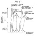
- Fig. 2 shows spectra obtained in practice in detail, taking the fluorescence spectrum as an example.
- the spectrum obtained by the fluorescence spectrophotometer includes scattered light of the excitation light and Raman scattering light apart from the peaks due to the fluorescence. Further, in the case where a spectroscope using a diffraction grating is used, it includes higher order scattering light such as second order scattering light of the excitation light, second order Raman scattering light, etc.
- a spectroscope using a diffraction grating it includes higher order scattering light such as second order scattering light of the excitation light, second order Raman scattering light, etc.
- the fluorescence spectrophotometer is constructed so as to have a function to find automatically the peaks due to the fluorescence, which are objects to be measured, in the following way.
- a property is utilized that the wavelength of the peaks due to the fluorescence doesn't vary, when the excitation wavelength is varied, but the wavelength of the other varies, depending on variations in the excitation wavelength.
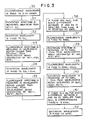
- Fig. 3 shows a flowchart of the computer 9 for distinguishing the peaks due to the fluorescence and setting the excitation wavelength and the fluorescence wavelength to the optimum wavelength of the sample and Figs. 4A to 4F indicate signal waveforms in the course of the processing thereof.
- the fluorescence wavelength is set at the O-th order and the excitation spectrum is measured (step 30 in Fig. 3).
- the wavelength of the maximum peak in the obtained spectrum is stored as EX1 (Step 31 in Fig. 3, Fig. 4A).
- EX1 represents a wavelength provisionally determined and it is not always in accordance with the optimum excitation wavelength.
- the excitation wavelength is fixed at EX1 (Step 32 in Fig. 3).
- the fluorescence spectrum is measured in the wavelength region longer than EX1 + 10 nm. It is for the purpose of excluding the peak due to scattered light of the excitation light that the measurement is effected from EX1 + 10 nm.
- this difference from EX1 can be selected arbitrarily, depending on various conditions such as the slit width in the fluorescence spectrophotometer.
- supposing that the slit is 10 nm wide as an example.
- the peaks in the obtained fluorescence spectrum are searched and numbered as W(1), W(2), owing in the decreasing order.
- the excitation wavelength is varied by 10 nm
- the amount of the variation in the second order scattering light of the excitation light is 20 nm; that in the Raman scattering light is 12 nm at 200 nm, which is the smallest wavelength for usual fluorescence spectrophotometers; and that in the second order scattering light is 24 nm.
- the limit of the margin is determined to be 11 nm. Upto here the optimum wavelength on the fluorescence side was found. Consequently, by setting this optimum wavelength for the peak wavelength due to the fluorescence, it is possible to set it for the appropriate wavelength, even in the case where the concentration of the sample is low.
- the processing as described below is performed. That is, in order to find the optimum wavelength on the excitation side, the fluorescence wavelength is fixed to EMWL stated above (Step 37 in Fig. 3) and the excitation spectrum is measured to EMWL-10 nm. The peaks in the obtained spectrum are searched and numbered as W(1), W(2), certainly in the decreasing order. The peak wavelengths are stored (Step 38 in Fig. 3, Fig. 4D). Next the fluorescence wavelength is fixed to EMWL + 20 nm (Step 39 in Fig. 3) and the excitation spectrum is measured again upto EMWL-10 nm.
- the peaks in the obtained spectrum are numbered as W p (1), W p (2), 7-8 and the wavelengths thereof are stored (Step 40 in Fig. 3, Fig. 4E).
- Ws are compared with W p s. If there is a W p , for which the difference is smaller than 8 nm, the W corresponding thereto is the excitation side optimum wavelength EXWL (Step 41 in Fig. 3, Fig. 4F).
- the wavelength of the scattered light varies only by 1/2, i.e. by 10 nm, on the excitation spectrum for an amount of the shift on the fluorescence side that the amount of the shift on the fluorescence side is determined to be 20 nm. For this reason the reference, on the basis of which the optimum wavelength is detected, is determined within a limit of 8 nm.
- the provisional excitation wavelength EX1 which is the starting point for the embodiment described above, may be set at another wavelength and the content of Fig. 3 may be again carried out.
- EX1 at this time may be either the second peak wavelength or another following in the excitation spectrum (Fig. 4A) obtained when the fluorescence is set at the O-th order or a value simply shifted from EX1 in the embodiment stated above by an arbitrary wavelength.
Landscapes
- Physics & Mathematics (AREA)
- Spectroscopy & Molecular Physics (AREA)
- General Physics & Mathematics (AREA)
- Investigating, Analyzing Materials By Fluorescence Or Luminescence (AREA)
- Spectrometry And Color Measurement (AREA)
Applications Claiming Priority (2)
| Application Number | Priority Date | Filing Date | Title |
|---|---|---|---|
| JP63039417A JPH073366B2 (ja) | 1988-02-24 | 1988-02-24 | 分光蛍光光度計 |
| JP39417/88 | 1988-02-24 |
Publications (3)
| Publication Number | Publication Date |
|---|---|
| EP0330183A2 true EP0330183A2 (de) | 1989-08-30 |
| EP0330183A3 EP0330183A3 (de) | 1991-07-17 |
| EP0330183B1 EP0330183B1 (de) | 1994-01-12 |
Family
ID=12552410
Family Applications (1)
| Application Number | Title | Priority Date | Filing Date |
|---|---|---|---|
| EP89103100A Expired - Lifetime EP0330183B1 (de) | 1988-02-24 | 1989-02-22 | Fluoreszenz-Spektralphotometer und dafür verwendetes Verfahren zur Festlegung der Wellenlänge |
Country Status (4)
| Country | Link |
|---|---|
| US (1) | US4957366A (de) |
| EP (1) | EP0330183B1 (de) |
| JP (1) | JPH073366B2 (de) |
| DE (1) | DE68912156T2 (de) |
Cited By (2)
| Publication number | Priority date | Publication date | Assignee | Title |
|---|---|---|---|---|
| EP0481823A1 (de) * | 1990-10-19 | 1992-04-22 | Shimadzu Corporation | Fluoreszenzmessgerät |
| EP0875747A3 (de) * | 1997-04-30 | 1999-06-02 | Anritsu Corporation | Apparat zur Messung eines optischen Transmissionsmerkmals und zugehörgies Kalibrierverfahren |
Families Citing this family (8)
| Publication number | Priority date | Publication date | Assignee | Title |
|---|---|---|---|---|
| US5151869A (en) * | 1990-02-16 | 1992-09-29 | The Boc Group, Inc. | Frequency domain fluorometry using coherent sampling |
| DE4142384A1 (de) * | 1991-12-20 | 1993-06-24 | Bayerische Motoren Werke Ag | Kunststoffbauteil fuer kraftfahrzeuge |
| JPH06109542A (ja) * | 1992-09-29 | 1994-04-19 | Shimadzu Corp | 分光蛍光光度計 |
| US5796476A (en) * | 1995-06-28 | 1998-08-18 | Kyoto Dai-Ichi Kagaku Co., Ltd. | Method of optically measuring component in solution |
| US6232609B1 (en) * | 1995-12-01 | 2001-05-15 | Cedars-Sinai Medical Center | Glucose monitoring apparatus and method using laser-induced emission spectroscopy |
| JP5488360B2 (ja) * | 2010-09-14 | 2014-05-14 | 株式会社島津製作所 | 分光蛍光光度計 |
| CN103134590A (zh) * | 2013-01-31 | 2013-06-05 | 南京邮电大学 | 一种实时动态测试磷光光谱的方法 |
| AT517366B1 (de) | 2015-06-22 | 2017-07-15 | Univ Wien Tech | Verfahren und Vorrichtung zur Bestimmung einer Materialeigenschaft eines Bitumenmaterials |
Family Cites Families (3)
| Publication number | Priority date | Publication date | Assignee | Title |
|---|---|---|---|---|
| US4178102A (en) * | 1977-09-20 | 1979-12-11 | U.S. Philips Corporation | Process and apparatus for measuring the concentration of a molecule of selective spectrum in a sample substance |
| JPS54158288A (en) * | 1978-06-05 | 1979-12-13 | Hitachi Ltd | Spectroscopic fluorescent photometer |
| JPS6221952Y2 (de) * | 1979-12-18 | 1987-06-04 |
-
1988
- 1988-02-24 JP JP63039417A patent/JPH073366B2/ja not_active Expired - Lifetime
-
1989
- 1989-02-22 US US07/313,440 patent/US4957366A/en not_active Expired - Lifetime
- 1989-02-22 EP EP89103100A patent/EP0330183B1/de not_active Expired - Lifetime
- 1989-02-22 DE DE89103100T patent/DE68912156T2/de not_active Expired - Lifetime
Cited By (4)
| Publication number | Priority date | Publication date | Assignee | Title |
|---|---|---|---|---|
| EP0481823A1 (de) * | 1990-10-19 | 1992-04-22 | Shimadzu Corporation | Fluoreszenzmessgerät |
| US5212538A (en) * | 1990-10-19 | 1993-05-18 | Shimadzu Corporation | Fluorescence measurement apparatus with an automatic recorder full-scale setting function |
| EP0875747A3 (de) * | 1997-04-30 | 1999-06-02 | Anritsu Corporation | Apparat zur Messung eines optischen Transmissionsmerkmals und zugehörgies Kalibrierverfahren |
| US6069697A (en) * | 1997-04-30 | 2000-05-30 | Anritsu Corporation | Optical transmission characteristic measuring apparatus and calibration method using the same |
Also Published As
| Publication number | Publication date |
|---|---|
| DE68912156D1 (de) | 1994-02-24 |
| US4957366A (en) | 1990-09-18 |
| EP0330183B1 (de) | 1994-01-12 |
| EP0330183A3 (de) | 1991-07-17 |
| JPH073366B2 (ja) | 1995-01-18 |
| JPH01214723A (ja) | 1989-08-29 |
| DE68912156T2 (de) | 1994-04-28 |
Similar Documents
| Publication | Publication Date | Title |
|---|---|---|
| EP0551736B1 (de) | Schnelle Kreuzkorrelation Frequenzbereichs Fluorometrie/Phosphorimetrie | |
| US4957366A (en) | Fluorescence spectrophotometer and wavelength setting method therefor | |
| EP1731896A1 (de) | Fluoreszenzspektroskopische vorrichtung | |
| JPH1038807A (ja) | プラスチックの判別方法およびプラスチックの判別装置 | |
| JPS6217695B2 (de) | ||
| JPS58120154A (ja) | プラズマ分布モニタ方法 | |
| US5212538A (en) | Fluorescence measurement apparatus with an automatic recorder full-scale setting function | |
| US7456951B2 (en) | Fluorescence detection method, detection apparatus and fluorescence detection program | |
| US20030115937A1 (en) | Liquid chromatographic analysis apparatus and liquid chromatographic analyzing method | |
| GB2213928A (en) | Wavelength scanning spectrophotometer | |
| GB2070765A (en) | Spectrophotometry | |
| RU2233438C1 (ru) | Способ дистанционного обнаружения и идентификации объектов органического происхождения | |
| JPS6336147A (ja) | ゲル電気泳動装置 | |
| JP4754888B2 (ja) | 発光分光分析方法及び発光分光分析装置 | |
| US6903817B2 (en) | Method for optically detecting chemical species contained in condensed media | |
| JPH03144347A (ja) | 蛍光分光光度法及びその装置 | |
| WO2017048844A1 (en) | System and method for filter configuration | |
| US20070091306A1 (en) | Method and apparatus for detection and analysis of biological materials through laser induced fluorescence | |
| JP3624587B2 (ja) | 蛍光測定装置 | |
| JP3203624B2 (ja) | レーザー蛍光検出装置 | |
| JPS63259439A (ja) | 半導体レ−ザ評価装置 | |
| US4171912A (en) | Element analyzer exploiting a magneto-optic effect | |
| WO2021189129A1 (en) | A system and method for detecting single elemental emission lines in a glow discharge | |
| JPS63241456A (ja) | 表面分析装置 | |
| Zhu et al. | Simultaneous dual-window measurements with a linear photodiode array detector |
Legal Events
| Date | Code | Title | Description |
|---|---|---|---|
| PUAI | Public reference made under article 153(3) epc to a published international application that has entered the european phase |
Free format text: ORIGINAL CODE: 0009012 |
|
| AK | Designated contracting states |
Kind code of ref document: A2 Designated state(s): DE GB |
|
| 17P | Request for examination filed |
Effective date: 19901212 |
|
| PUAL | Search report despatched |
Free format text: ORIGINAL CODE: 0009013 |
|
| AK | Designated contracting states |
Kind code of ref document: A3 Designated state(s): DE GB |
|
| 17Q | First examination report despatched |
Effective date: 19921030 |
|
| GRAA | (expected) grant |
Free format text: ORIGINAL CODE: 0009210 |
|
| AK | Designated contracting states |
Kind code of ref document: B1 Designated state(s): DE GB |
|
| REF | Corresponds to: |
Ref document number: 68912156 Country of ref document: DE Date of ref document: 19940224 |
|
| PLBE | No opposition filed within time limit |
Free format text: ORIGINAL CODE: 0009261 |
|
| STAA | Information on the status of an ep patent application or granted ep patent |
Free format text: STATUS: NO OPPOSITION FILED WITHIN TIME LIMIT |
|
| 26N | No opposition filed | ||
| REG | Reference to a national code |
Ref country code: GB Ref legal event code: IF02 |
|
| PGFP | Annual fee paid to national office [announced via postgrant information from national office to epo] |
Ref country code: GB Payment date: 20080114 Year of fee payment: 20 |
|
| PGFP | Annual fee paid to national office [announced via postgrant information from national office to epo] |
Ref country code: DE Payment date: 20080307 Year of fee payment: 20 |
|
| REG | Reference to a national code |
Ref country code: GB Ref legal event code: PE20 Expiry date: 20090221 |
|
| PG25 | Lapsed in a contracting state [announced via postgrant information from national office to epo] |
Ref country code: GB Free format text: LAPSE BECAUSE OF EXPIRATION OF PROTECTION Effective date: 20090221 |