EP0330457A2 - Optische Serienfilter - Google Patents
Optische Serienfilter Download PDFInfo
- Publication number
- EP0330457A2 EP0330457A2 EP89301741A EP89301741A EP0330457A2 EP 0330457 A2 EP0330457 A2 EP 0330457A2 EP 89301741 A EP89301741 A EP 89301741A EP 89301741 A EP89301741 A EP 89301741A EP 0330457 A2 EP0330457 A2 EP 0330457A2
- Authority
- EP
- European Patent Office
- Prior art keywords
- waveguide
- coupled
- filter according
- light
- optical
- Prior art date
- Legal status (The legal status is an assumption and is not a legal conclusion. Google has not performed a legal analysis and makes no representation as to the accuracy of the status listed.)
- Withdrawn
Links
Images

Classifications
-
- G—PHYSICS
- G02—OPTICS
- G02B—OPTICAL ELEMENTS, SYSTEMS OR APPARATUS
- G02B6/00—Light guides; Structural details of arrangements comprising light guides and other optical elements, e.g. couplings
- G02B6/24—Coupling light guides
- G02B6/26—Optical coupling means
- G02B6/28—Optical coupling means having data bus means, i.e. plural waveguides interconnected and providing an inherently bidirectional system by mixing and splitting signals
-
- G—PHYSICS
- G02—OPTICS
- G02B—OPTICAL ELEMENTS, SYSTEMS OR APPARATUS
- G02B6/00—Light guides; Structural details of arrangements comprising light guides and other optical elements, e.g. couplings
- G02B6/10—Light guides; Structural details of arrangements comprising light guides and other optical elements, e.g. couplings of the optical waveguide type
- G02B6/12—Light guides; Structural details of arrangements comprising light guides and other optical elements, e.g. couplings of the optical waveguide type of the integrated circuit kind
- G02B6/12007—Light guides; Structural details of arrangements comprising light guides and other optical elements, e.g. couplings of the optical waveguide type of the integrated circuit kind forming wavelength selective elements, e.g. multiplexer, demultiplexer
-
- G—PHYSICS
- G02—OPTICS
- G02B—OPTICAL ELEMENTS, SYSTEMS OR APPARATUS
- G02B6/00—Light guides; Structural details of arrangements comprising light guides and other optical elements, e.g. couplings
- G02B6/10—Light guides; Structural details of arrangements comprising light guides and other optical elements, e.g. couplings of the optical waveguide type
- G02B6/12—Light guides; Structural details of arrangements comprising light guides and other optical elements, e.g. couplings of the optical waveguide type of the integrated circuit kind
- G02B6/122—Basic optical elements, e.g. light-guiding paths
- G02B6/125—Bends, branchings or intersections
-
- G—PHYSICS
- G02—OPTICS
- G02B—OPTICAL ELEMENTS, SYSTEMS OR APPARATUS
- G02B6/00—Light guides; Structural details of arrangements comprising light guides and other optical elements, e.g. couplings
- G02B6/10—Light guides; Structural details of arrangements comprising light guides and other optical elements, e.g. couplings of the optical waveguide type
- G02B6/14—Mode converters
-
- G—PHYSICS
- G02—OPTICS
- G02B—OPTICAL ELEMENTS, SYSTEMS OR APPARATUS
- G02B6/00—Light guides; Structural details of arrangements comprising light guides and other optical elements, e.g. couplings
- G02B6/24—Coupling light guides
- G02B6/26—Optical coupling means
- G02B6/28—Optical coupling means having data bus means, i.e. plural waveguides interconnected and providing an inherently bidirectional system by mixing and splitting signals
- G02B6/2804—Optical coupling means having data bus means, i.e. plural waveguides interconnected and providing an inherently bidirectional system by mixing and splitting signals forming multipart couplers without wavelength selective elements, e.g. "T" couplers, star couplers
Definitions
- This invention relates to an optical in-line filter, that is to a filter for passing only a desired wavelength component of an input optical signal, and is particularly useful in an integrated optical device.
- the invention provides an optical in-line filter comprising a first, multi-mode waveguide whose output end is coupled to an open end of a second, narrower waveguide the said coupling and the length of the first waveguide being such that light entering the first waveguide undergoes interference between at least two of its modes causing light from the first waveguide of substantially a predetermined wavelength or wavelengths only to be passed to the second waveguide, light of other wavelengths emerging elsewhere from the output end of the first waveguide.
- the first waveguide supports at least three different transverse modes, so that the transverse power distribution oscillates as a function of the length along the waveguide.
- the length of the waveguide may therefore be selected precisely such that, for the optical waveband which is required to be selected by the second waveguide, the optical power is at a maximum at the interface between the first and second waveguides.
- this interface is at a central region of the first waveguide.
- the second waveguide is coupled so as to collect light from a central region of the open end of the first waveguide.
- light entering the first waveguide undergoes interference between its first (fundamental) and third order modes, although other modes may be chosen by suitably configuring the filter.
- interference may be arranged to occur between both symmetric and asymmetric modes.
- a waveguide section of greater width than the first waveguide may be arranged at its input end, and may have smoothly shaped edges, giving it a "bulbous configuration".
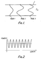
- an optical wave propagating along a waveguide 10 in a direction P may be supported in one or more modes: mode 1 (symmetric), mode 2 (asymmetric) and mode 3 (symmetric) being the first three of the series.
- the overall optical power at the particular wavelength concerned is the summation of the amplitudes of all these modes, and the power at any given transverse position oscillates as a function of the distance along the length of the waveguide 1.
- the variation in the power with distance along the centre-line of the waveguide 1 is illustrated in Figure 2.
- the positions of minima and maxima along the waveguide 1 depend (among other things) on the wavelength of the light, and the invention exploits this phenomenon by collecting from the output end of the waveguide only those wavelengths for which the maximum power lies at a predetermined transverse region of the waveguide end.
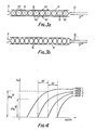
- the resulting optical filter is an in-line filter, and one example is shown in Figures 3a and 3b.
- a three-mode waveguide 10 receives light at a central transverse region of one end, from a waveguide 11. This excites almost exclusively mode 1 and mode 3 vibrations, since this combination of modes has a wave function, as shown in Figure 1, with an amplitude peak at the central region.
- the fundamental mode (mode 1) of the input waveguide 11 excites the first and third order modes of waveguide 10.
- An output waveguide 12 which is narrower than the width of the main waveguide 10, being typically 30% to 50% of its width, is placed in line with the main waveguide 10 with its open end coupled to a central region of the open end of the main waveguide 10 remote from the input waveguide 11.
- Light of a waveband, as shown in Figure 3a, which has a power maximum at the central end region of the waveguide 10 is passed into the output waveguide 12, with very little power loss externally of the output waveguide. This condition is satisfied by a series of wavebands. Light which does not satisfy this condition, as shown in Figure 3b, emerges elsewhere from the open end of the main waveguide 10.
- baffle points 131 are also shown in Figure 3a. These may be formed as scattering points or absorption points.
- the waveguides are formed as an integrated optical structure in a lithium niobate substrate, using conventional materials, and manufactured conventionally, for example by proton exchange and titanium diffusion.
- the scattering points or absorption points 13 may be formed for example by carrier diffusion, from gas or solid states, or by ion implantation.
- the width of the output waveguide 12 may be made sufficiently small to discriminate between wavelengths to the degree required over a given propagation length, yet sufficiently great to avoid excessive power loss. Further, in this embodiment of the invention, the width must support at least three modes but exclude the fifth mode.
- the width of the main waveguide 10 is selected within the range R2 in which modes 1, 2 and 3 are all supported and in which the difference ⁇ n between the effective refractive indices of the waveguide for modes 1 and 3 is substantial so as to provide a good coupling strength between the modes, which in turn reduces the length of waveguide required.
- the narrower widths in range R2 give the best coupling strength and are preferred.
- the width could be greater than range R2, so as to support mode 4, provided that the next symmetric mode, mode 5, is not also supported.
- the range R1 of widths of a two mode interferometer device is also shown in Figure 4: the difference ⁇ n between the refractive indices for the two modes is substantially lower.
- the effective refractive index n e is equal to the propagation constant divided by the wave vector k, and is the effective index of a three-dimensional device, which may have multiple layers, when viewed as a two-dimensional device, as is the case in Figures 1 and 3.
- the device consists of a thin, strip-like channel on the surface of a substrate, so that the channel acts in effect as a two-dimensional waveguide.
- n e i i is the effective refractive index for mode i: the coupling strength K relates to modes i and j.
- the optical in-line filter of Figure 3a is incorporated into a more complex filter.
- Light from an optical fibre 50 with a core 51 is collected by a single mode waveguide 52 with an output end 11 coupled to the waveguide 10.
- the output waveguide 12, coupled to the central region of the main waveguide 10, provides light at one filtered waveband to a detector 55.
- Most of the remaining output light is collected by a further pair of symmetrically-disposed output waveguides 53 whose outputs are either detected by one or both of two further detectors 58, 59 or else are recombined in a multi-mode waveguide 54, in series with the main waveguide 10.
- the light in waveguides 53 and 54 contains those frequencies which have not been filtered out by the first filter 10, 12, 53.
- This light may simply be detected in a further detector 56 (an alternative to detectors 58, 59), or instead it may be filtered once again at 57 by an optical in-line filter similar to the first one but arranged to filter different wavebands.
- the filter can terminate with the adjacent detectors 55, 58 and 59: the outputs of detectors 58 and 59 could be combined.
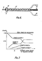
- an optical in-line filter comprises a bulbous waveguide section 60 to which light may be applied via waveguide 61, a multi-mode waveguide section 62 which is arranged to receive light from the bulbous section 60 and which is capable of supporting three modes, and three output waveguides 63, 64 and 65.
- the central output waveguide 64 is arranged along the longitudinal axis of section 62 and the other two output waveguides 63 and 65 are arranged at the edges of section 62 at its output.
- the greatest width of the bulbous section 60 supports six modes and enables good mixing to be achieved between the first and third order modes.
- Figure 7 schematically illustrates the modal power distribution along the centre line of the bulbous section 60. It can be seen that, at the output of the bulbous section 60, there is an equal distribution of power between the first and third order modes. Interference between the first and third order modes produces the power distribution along the section 62 as shown in Figure 6, where the amount of shading indicates the optical power at a given location. For the wavelength illustrated, it can be seen that the power is coupled out of section 62 along the central output waveguide 64. At another wavelength, the greatest energy intensity is towards the edges of section 62 at its output and therefore optical power is coupled into the other two waveguides 63 and 65, these two guides together forming a single output port. The central guide 64 forms another port.
- the use of the bulbous section 60 thus enables equal powers to be obtained in the first and third order modes, thus optimising the launch conditions into the multi-mode section 62.
Landscapes
- Physics & Mathematics (AREA)
- General Physics & Mathematics (AREA)
- Optics & Photonics (AREA)
- Engineering & Computer Science (AREA)
- Microelectronics & Electronic Packaging (AREA)
- Optical Integrated Circuits (AREA)
Applications Claiming Priority (4)
| Application Number | Priority Date | Filing Date | Title |
|---|---|---|---|
| GB8804569 | 1988-02-26 | ||
| GB888804569A GB8804569D0 (en) | 1988-02-26 | 1988-02-26 | Optical in-line filter |
| GB8823005A GB2215482B (en) | 1988-02-26 | 1988-09-30 | Optical in-line filter |
| GB8823005 | 1988-09-30 |
Publications (2)
| Publication Number | Publication Date |
|---|---|
| EP0330457A2 true EP0330457A2 (de) | 1989-08-30 |
| EP0330457A3 EP0330457A3 (de) | 1991-08-07 |
Family
ID=26293546
Family Applications (1)
| Application Number | Title | Priority Date | Filing Date |
|---|---|---|---|
| EP19890301741 Withdrawn EP0330457A3 (de) | 1988-02-26 | 1989-02-22 | Optische Serienfilter |
Country Status (2)
| Country | Link |
|---|---|
| US (1) | US4952018A (de) |
| EP (1) | EP0330457A3 (de) |
Cited By (9)
| Publication number | Priority date | Publication date | Assignee | Title |
|---|---|---|---|---|
| EP0461991A1 (de) * | 1990-06-13 | 1991-12-18 | Commissariat A L'energie Atomique | Integriertes optisches Monomode-Raumfilter und Verfahren zu seiner Herstellung |
| EP0482461A1 (de) * | 1990-10-22 | 1992-04-29 | Oy Nokia Ab | Mach-Zehnder Interferometer für Multi-/Demultiperxer |
| WO1992011562A1 (en) * | 1990-12-20 | 1992-07-09 | The Secretary Of State For Defence In Her Britannic Majesty's Government Of The United Kingdom Of Great Britain And Northern Ireland | Optical mixing device |
| WO1992011554A3 (en) * | 1990-12-20 | 1992-08-06 | Secr Defence Brit | Intensity dividing device |
| US5410625A (en) * | 1990-12-20 | 1995-04-25 | The Secretary Of State For Defence In Her Britannic Majesty's Government Of The United Kingdom Of Great Britain And Northern Ireland | Optical device for beam splitting and recombining |
| US5428698A (en) * | 1990-12-20 | 1995-06-27 | The Secretary Of State For Defense In Her Britannic Majesty's Government Of The United Kingdom Of Great Britain And Northern Ireland | Signal routing device |
| EP0660550A1 (de) * | 1993-12-20 | 1995-06-28 | AT&T Corp. | Sohton-Übertragungssystemzwischenverstärker mit Gleitfrequenzleitfiltern |
| EP0687926A1 (de) * | 1994-06-17 | 1995-12-20 | Koninklijke KPN N.V. | Optischer Leistungsteilerschaltkreis unabhängig von der Polarisation und Wellenlänge |
| EP0563065B1 (de) * | 1990-12-20 | 1997-07-16 | The Secretary of State for Defence in Her Britannic Majesty's Government of the United Kingdom of Great Britain and | Signalweglenkungsvorrichtung |
Families Citing this family (2)
| Publication number | Priority date | Publication date | Assignee | Title |
|---|---|---|---|---|
| US5627929A (en) * | 1995-05-04 | 1997-05-06 | Sandia Corporation | Integrated optical XY coupler |
| JP6540071B2 (ja) * | 2015-02-13 | 2019-07-10 | 沖電気工業株式会社 | 光導波路素子 |
Family Cites Families (7)
| Publication number | Priority date | Publication date | Assignee | Title |
|---|---|---|---|---|
| JPS5013061A (de) * | 1973-06-05 | 1975-02-10 | ||
| GB1558527A (en) * | 1977-07-21 | 1980-01-03 | Standard Telephones Cables Ltd | Optical fibre |
| US4674827A (en) * | 1982-05-20 | 1987-06-23 | Masayuki Izutsu | Slab-type optical device |
| US4701009A (en) * | 1985-02-04 | 1987-10-20 | Hughes Aircraft Company | Spectral filter for integrated optics |
| SE461482B (sv) * | 1986-05-16 | 1990-02-19 | Ericsson Telefon Ab L M | Optoelektronisk riktkopplare med likspaenningsfri styrsignal |
| US4820009A (en) * | 1987-08-13 | 1989-04-11 | Trw Inc. | Electrooptical switch and modulator |
| US4846540A (en) * | 1988-01-25 | 1989-07-11 | Bell Communications Research, Inc. | Optical wavegide junction |
-
1989
- 1989-02-22 EP EP19890301741 patent/EP0330457A3/de not_active Withdrawn
- 1989-02-23 US US07/313,787 patent/US4952018A/en not_active Expired - Fee Related
Cited By (19)
| Publication number | Priority date | Publication date | Assignee | Title |
|---|---|---|---|---|
| EP0461991A1 (de) * | 1990-06-13 | 1991-12-18 | Commissariat A L'energie Atomique | Integriertes optisches Monomode-Raumfilter und Verfahren zu seiner Herstellung |
| FR2663435A1 (fr) * | 1990-06-13 | 1991-12-20 | Commissariat Energie Atomique | Filtre optique spatial monomode integre et son procede de fabrication. |
| US5093884A (en) * | 1990-06-13 | 1992-03-03 | Commissariat A L'energie Atomique | Integrated monomode spatial optical filter and its method of embodiment |
| EP0482461A1 (de) * | 1990-10-22 | 1992-04-29 | Oy Nokia Ab | Mach-Zehnder Interferometer für Multi-/Demultiperxer |
| US5396570A (en) * | 1990-12-20 | 1995-03-07 | The Secretary Of State For Defence In Her Britannic Majesty's Government Of The United Kingdom Of Great Britain And Northern Ireland | Optical device for beam splitting, mixing and recombination functions |
| EP0563065B1 (de) * | 1990-12-20 | 1997-07-16 | The Secretary of State for Defence in Her Britannic Majesty's Government of the United Kingdom of Great Britain and | Signalweglenkungsvorrichtung |
| WO1992011554A3 (en) * | 1990-12-20 | 1992-08-06 | Secr Defence Brit | Intensity dividing device |
| US5379354A (en) * | 1990-12-20 | 1995-01-03 | The Secretary Of State For Defence In Her Britannic Majesty's Government Of The United Kingdom And Northern Ireland | Intensity dividing multimode wave guide device for producing intensity distribution maxima |
| WO1992011562A1 (en) * | 1990-12-20 | 1992-07-09 | The Secretary Of State For Defence In Her Britannic Majesty's Government Of The United Kingdom Of Great Britain And Northern Ireland | Optical mixing device |
| US5410625A (en) * | 1990-12-20 | 1995-04-25 | The Secretary Of State For Defence In Her Britannic Majesty's Government Of The United Kingdom Of Great Britain And Northern Ireland | Optical device for beam splitting and recombining |
| US5428698A (en) * | 1990-12-20 | 1995-06-27 | The Secretary Of State For Defense In Her Britannic Majesty's Government Of The United Kingdom Of Great Britain And Northern Ireland | Signal routing device |
| WO1992011555A1 (en) | 1990-12-20 | 1992-07-09 | The Secretary Of State For Defence In Her Britannic Majesty's Government Of The United Kingdom Of Great Britain And Northern Ireland | Optical device |
| US5475776A (en) * | 1990-12-20 | 1995-12-12 | The Secretary Of State For Defence In Her Britannic Majesty's Government Of The United Kingdom Of Great Britain And Northern Ireland | Optical mixing device |
| EP0563084B1 (de) * | 1990-12-20 | 1999-07-28 | The Secretary of State for Defence in Her Britannic Majesty's Government of the United Kingdom of Great Britain and | Optische vorrichtung |
| EP0660550A1 (de) * | 1993-12-20 | 1995-06-28 | AT&T Corp. | Sohton-Übertragungssystemzwischenverstärker mit Gleitfrequenzleitfiltern |
| US5524156A (en) * | 1994-06-17 | 1996-06-04 | Koninklijke Ptt Nederland N.V. | Polarization and wavelength independent optical power splitting circuit |
| NL9400993A (nl) * | 1994-06-17 | 1996-02-01 | Nederland Ptt | Polarisatie- en golflengte-onafhankelijk optisch vermogen splitsend circuit. |
| EP0687926A1 (de) * | 1994-06-17 | 1995-12-20 | Koninklijke KPN N.V. | Optischer Leistungsteilerschaltkreis unabhängig von der Polarisation und Wellenlänge |
| EP1207409A1 (de) * | 1994-06-17 | 2002-05-22 | Koninklijke KPN N.V. | Polarisations- und wellenlängenunabhängiger optischer Leistungsteilerschaltkreis |
Also Published As
| Publication number | Publication date |
|---|---|
| EP0330457A3 (de) | 1991-08-07 |
| US4952018A (en) | 1990-08-28 |
Similar Documents
| Publication | Publication Date | Title |
|---|---|---|
| EP0444817B1 (de) | Optischer Multiplexer/Demultiplexer | |
| EP0938000B1 (de) | Lichtwellenleiterverzweigung mit Reflektor | |
| EP1629305B1 (de) | Optischer wellenleitergitter-koppler | |
| US5226100A (en) | Optical grating comprising a plurality of side-by-side outfeed end faces of optical waveguides | |
| US4673270A (en) | Channel add/drop filter-coupler | |
| US6643432B2 (en) | Optical waveguide device and optical waveguide method | |
| US4262995A (en) | Planar star coupler device for fiber optics | |
| EP0289332A1 (de) | Optisches Element | |
| US4952018A (en) | Optical in line filters | |
| WO1995034010A1 (en) | Spatial filter for improving polarization ration a proton exchange wave guide device | |
| US7302138B2 (en) | Arrayed waveguide grating device | |
| EP0701159B1 (de) | Optischer Wellenlangenfilter mit Seitebandenunterdrückung | |
| US6856735B2 (en) | Tap couplers for fiber optic arrays | |
| EP0220315B1 (de) | Geräte mit optischen wellenleitern und mit niedrigen verlusten | |
| CN102902010B (zh) | 信道损耗均匀的波导光栅器件 | |
| EP0826988A2 (de) | Integriert optische Notchfilter | |
| Ramer et al. | Experimental integrated optic circuit losses and fiber pigtailing of chips | |
| US6768572B2 (en) | Solid state free space switch array on a substrate | |
| US6787868B1 (en) | Microlenses for integrated optical devices | |
| EP0366302A2 (de) | Optischer Wellenlängen-Duplexer mit geführten Wellen | |
| Mao et al. | An ARROW optical wavelength filter: design and analysis | |
| GB2215482A (en) | Optical in-line filter | |
| EP1430342B1 (de) | Entzerrung des durchlassbandes in einem wellenleitergitter | |
| WO2001079915A2 (en) | Diffraction grating in the whispering gallery mount | |
| US6714704B2 (en) | Optical component having selected bandwidth |
Legal Events
| Date | Code | Title | Description |
|---|---|---|---|
| PUAI | Public reference made under article 153(3) epc to a published international application that has entered the european phase |
Free format text: ORIGINAL CODE: 0009012 |
|
| AK | Designated contracting states |
Kind code of ref document: A2 Designated state(s): AT CH DE FR IT LI SE |
|
| PUAL | Search report despatched |
Free format text: ORIGINAL CODE: 0009013 |
|
| AK | Designated contracting states |
Kind code of ref document: A3 Designated state(s): AT CH DE FR IT LI SE |
|
| 17P | Request for examination filed |
Effective date: 19910912 |
|
| RAP1 | Party data changed (applicant data changed or rights of an application transferred) |
Owner name: MATRA MARCONI SPACE (UK) LIMITED |
|
| RAP1 | Party data changed (applicant data changed or rights of an application transferred) |
Owner name: MATRA MARCONI SPACE UK LIMITED |
|
| STAA | Information on the status of an ep patent application or granted ep patent |
Free format text: STATUS: THE APPLICATION IS DEEMED TO BE WITHDRAWN |
|
| 18D | Application deemed to be withdrawn |
Effective date: 19920901 |