EP0330815A2 - Schutzgehäuse für Tachogenerator - Google Patents
Schutzgehäuse für Tachogenerator Download PDFInfo
- Publication number
- EP0330815A2 EP0330815A2 EP89100419A EP89100419A EP0330815A2 EP 0330815 A2 EP0330815 A2 EP 0330815A2 EP 89100419 A EP89100419 A EP 89100419A EP 89100419 A EP89100419 A EP 89100419A EP 0330815 A2 EP0330815 A2 EP 0330815A2
- Authority
- EP
- European Patent Office
- Prior art keywords
- tachometer generator
- cover
- gear box
- protective case
- coils
- Prior art date
- Legal status (The legal status is an assumption and is not a legal conclusion. Google has not performed a legal analysis and makes no representation as to the accuracy of the status listed.)
- Withdrawn
Links
Images

Classifications
-
- H—ELECTRICITY
- H02—GENERATION; CONVERSION OR DISTRIBUTION OF ELECTRIC POWER
- H02K—DYNAMO-ELECTRIC MACHINES
- H02K21/00—Synchronous motors having permanent magnets; Synchronous generators having permanent magnets
- H02K21/38—Synchronous motors having permanent magnets; Synchronous generators having permanent magnets with rotating flux distributors, and armatures and magnets both stationary
-
- G—PHYSICS
- G01—MEASURING; TESTING
- G01P—MEASURING LINEAR OR ANGULAR SPEED, ACCELERATION, DECELERATION, OR SHOCK; INDICATING PRESENCE, ABSENCE, OR DIRECTION, OF MOVEMENT
- G01P1/00—Details of instruments
- G01P1/02—Housings
- G01P1/026—Housings for speed measuring devices, e.g. pulse generator
-
- G—PHYSICS
- G01—MEASURING; TESTING
- G01P—MEASURING LINEAR OR ANGULAR SPEED, ACCELERATION, DECELERATION, OR SHOCK; INDICATING PRESENCE, ABSENCE, OR DIRECTION, OF MOVEMENT
- G01P3/00—Measuring linear or angular speed; Measuring differences of linear or angular speeds
- G01P3/42—Devices characterised by the use of electric or magnetic means
- G01P3/44—Devices characterised by the use of electric or magnetic means for measuring angular speed
- G01P3/48—Devices characterised by the use of electric or magnetic means for measuring angular speed by measuring frequency of generated current or voltage
- G01P3/481—Devices characterised by the use of electric or magnetic means for measuring angular speed by measuring frequency of generated current or voltage of pulse signals
- G01P3/488—Devices characterised by the use of electric or magnetic means for measuring angular speed by measuring frequency of generated current or voltage of pulse signals delivered by variable reluctance detectors
-
- H—ELECTRICITY
- H02—GENERATION; CONVERSION OR DISTRIBUTION OF ELECTRIC POWER
- H02K—DYNAMO-ELECTRIC MACHINES
- H02K5/00—Casings; Enclosures; Supports
- H02K5/04—Casings or enclosures characterised by the shape, form or construction thereof
- H02K5/12—Casings or enclosures characterised by the shape, form or construction thereof specially adapted for operating in liquid or gas
- H02K5/128—Casings or enclosures characterised by the shape, form or construction thereof specially adapted for operating in liquid or gas using air-gap sleeves or air-gap discs
-
- H—ELECTRICITY
- H02—GENERATION; CONVERSION OR DISTRIBUTION OF ELECTRIC POWER
- H02K—DYNAMO-ELECTRIC MACHINES
- H02K5/00—Casings; Enclosures; Supports
- H02K5/04—Casings or enclosures characterised by the shape, form or construction thereof
- H02K5/12—Casings or enclosures characterised by the shape, form or construction thereof specially adapted for operating in liquid or gas
- H02K5/128—Casings or enclosures characterised by the shape, form or construction thereof specially adapted for operating in liquid or gas using air-gap sleeves or air-gap discs
- H02K5/1282—Casings or enclosures characterised by the shape, form or construction thereof specially adapted for operating in liquid or gas using air-gap sleeves or air-gap discs the partition wall in the air-gap being non cylindrical
Definitions
- the present invention relates generally to a tachometer generator.
- a tachometer generator is used for the purpose of detecting the rotation of a rotary machinery.
- it is attached to the periphery of a driving gear in a vehicle e.g. electric car.
- the most important device of the tachometer generator is a coil part which generates an output voltage proportional to the number of rotation of the driving gear.
- the coil part is very elaborate, is easy to break by a mechanical shock, and is easily corroded by oil.
- the most portions of the coil part with pole piece and permanent magnet have been molded in synthetic resin as usual.
- the above-mentioned molding has some disadvantages as mentioned below.
- Locally concentrated stress in the mold is liable to be set up due to complex shape of the coil part and other molded parts. With the heat cycle and vibration from driving power source of a car that make the stress and residual stress stronger, the mold is liable to make cracks therein and results in failure of accomplishing its protective function.
- the ends of pole pieces of the coil being the important sensing part of the tachometer, it cannot be molded because the mold layer is generally thick, and destroy the sensitivity. Even if the ends of core of the coil is molded with very thin layer for sensitivity, such a thin mold layer should have cracks easily originated from the above-mentioned stress. Diffusion of lubrication oil and metal dust made by the gears through the above-mentioned cracks and a gap between the molding and the core of coil causes corrosion of coil and a shortcircuit or insufficiency of insulation.
- An object of the present invention is to provide a protective case of tachometer generator which has continuing protective effects against shocks, lubrication oil and filings in the above-mentioned harsh environment.
- a protective case of tachometer generator in accordance with the present invention comprises a gear box having a driving gear; a tachometer generator mounted on said gear box in a manner that a sensing element of said tachometer generator is in a position of proximation to said driving gear; and a non-magnetic cover fixed to said gear box in a manner to form a partition between said gear box and said tachometer generator.
- the cover Since the cover is not stuck on the surface of the tachometer generator like the prior art mold cover, the cover does not have the above-mentioned stress. Accordingly it makes no crack from such stress. All the surface of the tachometer generator is covered thereby disabling encroachment of lubrication oil.
- the coils or the permanent magnet such as parts of the tachometer generator can be detached and repaired or replaced without destroying any related components.
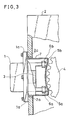
- a first preferred embodiment of the present invention is elucidated hereafter with reference to FIG.1 through FIG.3.
- a gear box 2 which is connected to a motor 9 of a car has a driving gear 4 therein.
- a tachometer generator 1 is removably mounted on the gear box 2 at flange joint 1a at the edge 2b of outer wall of the opening of the gear box 2.
- the tachometer generator 1 comprises a U-shaped yoke wherein a permanent magnet is situated at the central part 3 thereof.
- the end parts 5a, 5b of U-shaped yoke are a pair of pole pieces disposed parallel to each other. Respective ends of the iron cores 5a, 5b have coils 6a, 6b wounded therearound.
- a cover 7 made of non-magnetic material sheet covers and contains the tachometer generator 1 namely the permanent magnet 3, the pair of iron cores 5a, 5b with coils 6a, 6b therein without touching them, so as to protect the tachometer generator from lubrication oil and metal dust made by gears.
- the cover 7 is removably mounted on the gear box 2 by using flange joint 1a of the tachometer generator.
- the cover 7 also serves as partition between the gear box 2 and the tachometer generator 1 and is watertight.
- a material of the cover 7 must have the properties of non-magnetism, high shock resistance, flame retardance, non hygroscopicity, and high oil resistance with a condition of wide range of working temperature such as -20°C--+120°C.
- a synthetic resin such as FRP (Fiber Reinforced Plastics) made of polyester resin is one of many materials which have the above-mentioned properties, and the cover 7 made of such resin is made as follows: The cover 7 is molded in an integral body so as to agree with the shape of the tachometer generator comprising the permanent magnet 3, the iron cores 5a, 5b and the coils 6a, 6b by a cast.
- the cover 7 When mounted on the gear box 2 the cover 7 does not stick to none of the permanent magnet 3, the iron cores 5a, 5b or the coils 6a, 6b, thus stress caused by a heat cycle or vibration of the motor is not amplified. Therefore there is no mechanical disadvantage by the provision of the cover 7.
- the part of the cover 7 which is situated between the ends of pole pieces 5a, 5b, namely the sensing element of the tachometer generator and the gear facing thereto should have such a thin thickness as about 1 mm or less, and other parts of the cover 7 may have a thickness of between 2 mm and 3mm.
- the thickness of about 1 mm is experimentally found most suitable in view of attaining high production yield to produce the cover 7 with maintaining the sensitivity of the signal generation and also excluding any pin-holes or other defects. Through our experiments, the thickness at least a range from 1 mm to 5mm is found to satisfy the above-mentioned both conditions.
- a non-magnetic metal such as aluminum is usable for a metallic material of the cover 7.
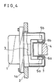
- a second preferred embodiment of the present invention is elucidated hereafter with reference to FIG.4. Corresponding parts and components to the first embodiment are shown by the same numerals and marks, and the description thereon made in the first embodiment similarly apply. Differences and features of this second embodiment from the first embodiment are as follows.
- the relative disposition of the ends of the iron cores 5a, 5b and coils 6a, 6b and the running direction of teeth of the driving gear 4 differs. It is a matter of course that the effect of the cover 7 is as same as the above-mentioned Embodiment 1.
- the surface of the cover 7 which faces to the driving gear 4 is flat, while the surface corresponding to the cover 7 in the Embodiment 1 is cylindrical. Therefore the embodiment 2 has advantages that the flat surface can be made more precisely and that the gap between the cover 7 and the driving gear 4 can be made narrower than the Embodiment 1.
- the cover 7 elucidated in the embodiment 1 and 2 covers a part of the tachometer generator 1 as a partition between the gear box 2 and the tachometer generator 1. It is a matter of course that the cover 7 can shelter all part of the tachometer generator 1 as a housing of the tachometer generator 1.
Landscapes
- Engineering & Computer Science (AREA)
- Power Engineering (AREA)
- Physics & Mathematics (AREA)
- General Physics & Mathematics (AREA)
- Permanent Magnet Type Synchronous Machine (AREA)
Applications Claiming Priority (2)
| Application Number | Priority Date | Filing Date | Title |
|---|---|---|---|
| JP17855/88 | 1988-01-28 | ||
| JP1785588A JPH01194844A (ja) | 1988-01-28 | 1988-01-28 | 速度発電機の保護装置 |
Publications (2)
| Publication Number | Publication Date |
|---|---|
| EP0330815A2 true EP0330815A2 (de) | 1989-09-06 |
| EP0330815A3 EP0330815A3 (de) | 1991-08-28 |
Family
ID=11955272
Family Applications (1)
| Application Number | Title | Priority Date | Filing Date |
|---|---|---|---|
| EP19890100419 Withdrawn EP0330815A3 (de) | 1988-01-28 | 1989-01-11 | Schutzgehäuse für Tachogenerator |
Country Status (4)
| Country | Link |
|---|---|
| EP (1) | EP0330815A3 (de) |
| JP (1) | JPH01194844A (de) |
| AU (1) | AU614575B2 (de) |
| MX (1) | MX171651B (de) |
Cited By (6)
| Publication number | Priority date | Publication date | Assignee | Title |
|---|---|---|---|---|
| FR2757704A1 (fr) * | 1996-12-20 | 1998-06-26 | Whitaker Corp | Ensemble a generatrice electrique monte sur un essieu |
| EP0783105A4 (de) * | 1995-07-21 | 1998-12-02 | Matsushita Electric Industrial Co Ltd | Magnetischer drehgeschwindigkeitssensor |
| RU2239841C2 (ru) * | 2002-12-26 | 2004-11-10 | Максидонов Анатолий Григорьевич | Датчик тахометрический |
| FR2925139A1 (fr) * | 2007-12-17 | 2009-06-19 | Sc2N Sa | Capteur de position d'une boite de vitesses et boite de vitesses correspondante |
| FR2932544A1 (fr) * | 2008-06-11 | 2009-12-18 | Peugeot Citroen Automobiles Sa | Dispositif de detection de position d'un mecanisme mobile se trouvant dans un carter contenant de l'huile |
| CN104521118A (zh) * | 2012-08-08 | 2015-04-15 | 东海旅客铁道株式会社 | 电枢轴支撑构造的损伤检测装置 |
Families Citing this family (1)
| Publication number | Priority date | Publication date | Assignee | Title |
|---|---|---|---|---|
| JP5335509B2 (ja) * | 2009-03-25 | 2013-11-06 | 本田技研工業株式会社 | 回転電機 |
Family Cites Families (7)
| Publication number | Priority date | Publication date | Assignee | Title |
|---|---|---|---|---|
| US3564313A (en) * | 1969-08-08 | 1971-02-16 | Trans Sonics Inc | Self-compensating tachometer generator |
| DE7806069U1 (de) * | 1978-03-01 | 1978-07-27 | Beru-Werk Albert Ruprecht Gmbh & Co Kg, 7140 Ludwigsburg | Induktiver impulsgeber |
| JPS60500225A (ja) * | 1983-01-28 | 1985-02-21 | キヤタピラ− トラクタ− カンパニ− | 隙間調整検知器 |
| DE3335864A1 (de) * | 1983-10-03 | 1985-04-11 | Robert Bosch Gmbh, 7000 Stuttgart | Induktiver stabsensor mit elektrischer spule |
| DE3344959C2 (de) * | 1983-12-13 | 1997-06-05 | Wabco Gmbh | Impulsdrehzahlgeber |
| FR2578018B1 (fr) * | 1985-02-26 | 1990-04-27 | Electricfil | Perfectionnements aux capteurs electromagnetiques |
| WO1987006348A1 (en) * | 1986-04-10 | 1987-10-22 | Caterpillar Inc. | Velocity sensor with drift compensation |
-
1988
- 1988-01-28 JP JP1785588A patent/JPH01194844A/ja active Pending
-
1989
- 1989-01-05 MX MX1444789A patent/MX171651B/es unknown
- 1989-01-11 EP EP19890100419 patent/EP0330815A3/de not_active Withdrawn
- 1989-01-27 AU AU28866/89A patent/AU614575B2/en not_active Ceased
Cited By (13)
| Publication number | Priority date | Publication date | Assignee | Title |
|---|---|---|---|---|
| EP0783105A4 (de) * | 1995-07-21 | 1998-12-02 | Matsushita Electric Industrial Co Ltd | Magnetischer drehgeschwindigkeitssensor |
| US6064200A (en) * | 1995-07-21 | 2000-05-16 | Matsushita Electric Industrial Co., Ltd. | Magnetic sensor with detection block, connector block and cap/cover |
| FR2757704A1 (fr) * | 1996-12-20 | 1998-06-26 | Whitaker Corp | Ensemble a generatrice electrique monte sur un essieu |
| RU2239841C2 (ru) * | 2002-12-26 | 2004-11-10 | Максидонов Анатолий Григорьевич | Датчик тахометрический |
| CN101946107B (zh) * | 2007-12-17 | 2014-04-23 | Sc2N公司 | 变速箱位置传感器和相应的变速箱 |
| WO2009106701A1 (fr) * | 2007-12-17 | 2009-09-03 | Sc2N | Capteur de position d'une boite de vitesses et boite de vitesses correspondante |
| CN101946107A (zh) * | 2007-12-17 | 2011-01-12 | Sc2N公司 | 变速箱位置传感器和相应的变速箱 |
| US8493063B2 (en) | 2007-12-17 | 2013-07-23 | Sc2N | Gearbox position sensor and corresponding gearbox |
| FR2925139A1 (fr) * | 2007-12-17 | 2009-06-19 | Sc2N Sa | Capteur de position d'une boite de vitesses et boite de vitesses correspondante |
| FR2932544A1 (fr) * | 2008-06-11 | 2009-12-18 | Peugeot Citroen Automobiles Sa | Dispositif de detection de position d'un mecanisme mobile se trouvant dans un carter contenant de l'huile |
| CN104521118A (zh) * | 2012-08-08 | 2015-04-15 | 东海旅客铁道株式会社 | 电枢轴支撑构造的损伤检测装置 |
| EP2884634A4 (de) * | 2012-08-08 | 2016-09-21 | Tokai Ryokaku Tetsudo Kk | Vorrichtung zum erkennung von schäden an einer stützstruktur für eine ankerwelle |
| CN104521118B (zh) * | 2012-08-08 | 2017-10-17 | 东海旅客铁道株式会社 | 电枢轴支撑构造的损伤检测装置 |
Also Published As
| Publication number | Publication date |
|---|---|
| JPH01194844A (ja) | 1989-08-04 |
| AU2886689A (en) | 1989-08-03 |
| MX171651B (es) | 1993-11-10 |
| EP0330815A3 (de) | 1991-08-28 |
| AU614575B2 (en) | 1991-09-05 |
Similar Documents
| Publication | Publication Date | Title |
|---|---|---|
| KR101752258B1 (ko) | 모터 | |
| US4564777A (en) | Reinforced permanent magnet rotor with cast zinc | |
| US6867518B2 (en) | Sealed motor and method of employing same | |
| US11050318B2 (en) | Drive device | |
| US5945759A (en) | Stepping motor | |
| JPH08509296A (ja) | 位置調整装置 | |
| GB2356978A (en) | An external rotor brushless dc motor | |
| EP0330815A2 (de) | Schutzgehäuse für Tachogenerator | |
| US20070046122A1 (en) | Rotary electric machine equipped with one or more magnetic sensors | |
| US11502563B2 (en) | Rotor, spoke type motor, vehicle motor, unmanned flying body, electric assist device, and robot device | |
| JPH03112344A (ja) | 回転電機の製造方法 | |
| GB2187557A (en) | Torque sensor and method of manufacturing the same | |
| US11177723B2 (en) | Rotor and motor | |
| WO2016194598A1 (ja) | ポンプ装置 | |
| US11489380B2 (en) | Rotor, spoke type motor, vehicle motor, unmanned flying body, electric assist device, and robot device | |
| WO2020053992A1 (ja) | 磁界遮蔽板付きエンコーダ | |
| JP6838306B2 (ja) | 車載用検出装置 | |
| WO2016103619A1 (ja) | 内燃機関用回転位置検出装置 | |
| EP0705973B1 (de) | Anlasser mit bandförmigem Abdichtungselement | |
| JPS5922784Y2 (ja) | フライホイルマグネツトの回転子 | |
| JP7339802B2 (ja) | 回転電機のセンサ構造 | |
| JPS58809Y2 (ja) | 電磁流量計検出器 | |
| JPH0842668A (ja) | 車両変速機および変速機用ファスナ部材 | |
| CN113243074A (zh) | 包括用于转子旋转参数的磁性检测器的转子 | |
| JP2713048B2 (ja) | 回転検出センサ |
Legal Events
| Date | Code | Title | Description |
|---|---|---|---|
| PUAI | Public reference made under article 153(3) epc to a published international application that has entered the european phase |
Free format text: ORIGINAL CODE: 0009012 |
|
| 17P | Request for examination filed |
Effective date: 19890111 |
|
| AK | Designated contracting states |
Kind code of ref document: A2 Designated state(s): ES FR GB |
|
| PUAL | Search report despatched |
Free format text: ORIGINAL CODE: 0009013 |
|
| AK | Designated contracting states |
Kind code of ref document: A3 Designated state(s): ES FR GB |
|
| RHK1 | Main classification (correction) |
Ipc: G01P 1/02 |
|
| 17Q | First examination report despatched |
Effective date: 19920904 |
|
| STAA | Information on the status of an ep patent application or granted ep patent |
Free format text: STATUS: THE APPLICATION IS DEEMED TO BE WITHDRAWN |
|
| 18D | Application deemed to be withdrawn |
Effective date: 19930115 |