EP0331261A1 - Appareil et méthode pour déterminer l'azimut, la déclivité et le roulement - Google Patents
Appareil et méthode pour déterminer l'azimut, la déclivité et le roulement Download PDFInfo
- Publication number
- EP0331261A1 EP0331261A1 EP89200482A EP89200482A EP0331261A1 EP 0331261 A1 EP0331261 A1 EP 0331261A1 EP 89200482 A EP89200482 A EP 89200482A EP 89200482 A EP89200482 A EP 89200482A EP 0331261 A1 EP0331261 A1 EP 0331261A1
- Authority
- EP
- European Patent Office
- Prior art keywords
- roll
- pitch
- determining
- magnetic field
- providing
- Prior art date
- Legal status (The legal status is an assumption and is not a legal conclusion. Google has not performed a legal analysis and makes no representation as to the accuracy of the status listed.)
- Granted
Links
- 238000000034 method Methods 0.000 title claims abstract description 13
- 230000004907 flux Effects 0.000 description 4
- 238000010586 diagram Methods 0.000 description 1
- 238000005259 measurement Methods 0.000 description 1
- 238000012986 modification Methods 0.000 description 1
- 230000004048 modification Effects 0.000 description 1
- 230000000737 periodic effect Effects 0.000 description 1
- 230000000717 retained effect Effects 0.000 description 1
- 238000006467 substitution reaction Methods 0.000 description 1
Images
Classifications
-
- G—PHYSICS
- G01—MEASURING; TESTING
- G01C—MEASURING DISTANCES, LEVELS OR BEARINGS; SURVEYING; NAVIGATION; GYROSCOPIC INSTRUMENTS; PHOTOGRAMMETRY OR VIDEOGRAMMETRY
- G01C17/00—Compasses; Devices for ascertaining true or magnetic north for navigation or surveying purposes
- G01C17/38—Testing, calibrating, or compensating of compasses
-
- G—PHYSICS
- G01—MEASURING; TESTING
- G01C—MEASURING DISTANCES, LEVELS OR BEARINGS; SURVEYING; NAVIGATION; GYROSCOPIC INSTRUMENTS; PHOTOGRAMMETRY OR VIDEOGRAMMETRY
- G01C17/00—Compasses; Devices for ascertaining true or magnetic north for navigation or surveying purposes
- G01C17/02—Magnetic compasses
- G01C17/28—Electromagnetic compasses
- G01C17/30—Earth-inductor compasses
-
- G—PHYSICS
- G01—MEASURING; TESTING
- G01R—MEASURING ELECTRIC VARIABLES; MEASURING MAGNETIC VARIABLES
- G01R33/00—Arrangements or instruments for measuring magnetic variables
- G01R33/02—Measuring direction or magnitude of magnetic fields or magnetic flux
- G01R33/0206—Three-component magnetometers
Definitions
- the present invention relates to compass apparatus and, in particular, compass apparatus which further provides azimuth pitch and roll signals.
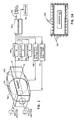
- FIG. 1 A block drawing of one embodiment of the system 50 is shown in Fig. 1 wherein a sensor 52, containing three orthogonal magnetic field sensing elements, typically flux gates, are retained within a structure having a pitch coil 54 and a roll coil 56 disposed thereabout to selectively provide a predetermined DC magnetic field for the process described below.
- the particular proportions of the pitch and roll coils 52 and 54 is shown more clearly in Fig. 1A, wherein the coils 52 and 54 comprise solenoidally wound coils which extend beyond the sensor 52 such that the lines of flux produced by the respective coils are substantially parallel and uniform in through the sensor 52.
- the signals derived by the individual flux gates in the sensor 52 are measured by elements 60, 62 and 64, and received by and stored in a processor 66.
- the processor sequentially and selectively energizes the pitch and roll coils 52 and 54 according to control signals applied to energization circuits 68 and 70, respectively.
- the resulting calculated pitch, roll and azimuth is provided on output leads 72 and/or selectively displayed on a display 74.
- the embodiment 50 includes a processor 66 which comprises typically a microprocessor such as the Intel MCS 48 Series Microprocessor, the Motorola 6800 Series Microprocessor or equivalent thereof and is programmed according to the following process according to the present invention by one of skill in the art.
- a processor 66 which comprises typically a microprocessor such as the Intel MCS 48 Series Microprocessor, the Motorola 6800 Series Microprocessor or equivalent thereof and is programmed according to the following process according to the present invention by one of skill in the art.
- the process of the present invention provides a periodic update of the pitch, roll and azimuth signals.
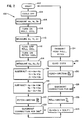
- One embodiment of the process is shown in the flow chart 100 in Fig. 2 wherein the process begins at step 102, and turns the coils off at step 104 so that X, Y and Z signals provided by the sensor 52 and measured by elements 60, 62 and 64, noted as Xe, Ye and Ze, correspond only to the ambient magnetic field (of the earth) Hx1, Hy1 and Hz1.
- the measurement is provided at step 106.
- the roll coil 52 in the Hz plane is energized at step 108 and the three signal orthogonal signals are measured at step 110 for the field components Hx2, Hy2 and Hz2 wherein the signals are noted as Xr, Yr and Zr.
- the roll coil 52 is de-energized and the pitch coil 54, in the Hy plane, is energized at step 112.
- the signals from the sensors are measured at step 114, providing the Xp, Yp and Zp signals, corresponding to Hx3, Hy3 and Hz3 comprising the ambient earth magnetic field and the field imposed by the pitch coil.
- the above steps of measuring the sensor signals with and without energization of the particular roll and pitch coils is accomplished in a short interval, such as 15 milliseconds, in order to provide a "snapshot" of the ambient field conditions. If an extended period of time between the readings exists so that the platform to which the compass is attached changes its relative position, changes in ambient field conditions will cause erroneous calculations of the desired signals.
- the signals derived when all coils are off (Xe, Ye and Ze) is subtracted from the signals (Xr, Yr and Zr) derived when the roll coil is energized, resulting in difference signals XI, YI and ZI.
- the signals measured when the coils are not energized are subtracted from the signals (Zp, Yp and Zp) derived when the pitch coil is energized at step 118, providing signals XII, YII and ZII.
- step 120 the pitch (P) is calculated according to the arctangent of XI/ZI (arctangent (Hy2 - Hy1)/(Hz2 - Hz1)).
- step 122 a quadrant correction is applied such that if the Hx signal is less than 0, 180° is added to the value of pitch, and if Hx if greater than 0 and Hy is less than 0, a value of 360° is added to the calculated value of pitch.
- step 124 and ZI is multiplied by 1 + sin P where P is the calculated pitch angle.
- the roll (R) is calculated at step 126 according to the arctangent of YI/ZI (arctangent (Hy3 - Hy1)/(Hz3 - Hz1)), and is corrected at the optional step 128, which incorporates the quadrant correction according to step 122 as applied to the calculated roll angle.
- the heading ( ⁇ ) (azimuth) is calculated at step 130 according to the arctangent of the initially measured values of YE/XE (arctangent Hy1/Hx1).
- Quadrant correction is applied at the optional step 132, incorporating the procedure of step 122, discussed above, as applied to the calculated heading angle.
- the calculated heading, pitch and roll values are transmitted to the external apparatus or to the display 74 at step 134, whereupon the method of determining azimuth, pitch and roll according to the present invention is begun again at step 102.
Landscapes
- Physics & Mathematics (AREA)
- Engineering & Computer Science (AREA)
- Radar, Positioning & Navigation (AREA)
- Remote Sensing (AREA)
- General Physics & Mathematics (AREA)
- Condensed Matter Physics & Semiconductors (AREA)
- Life Sciences & Earth Sciences (AREA)
- Environmental & Geological Engineering (AREA)
- General Life Sciences & Earth Sciences (AREA)
- Geology (AREA)
- Electromagnetism (AREA)
- Measuring Magnetic Variables (AREA)
Applications Claiming Priority (2)
| Application Number | Priority Date | Filing Date | Title |
|---|---|---|---|
| US16200788A | 1988-02-29 | 1988-02-29 | |
| US162007 | 1988-02-29 |
Publications (2)
| Publication Number | Publication Date |
|---|---|
| EP0331261A1 true EP0331261A1 (fr) | 1989-09-06 |
| EP0331261B1 EP0331261B1 (fr) | 1993-04-28 |
Family
ID=22583771
Family Applications (1)
| Application Number | Title | Priority Date | Filing Date |
|---|---|---|---|
| EP89200482A Expired - Lifetime EP0331261B1 (fr) | 1988-02-29 | 1989-02-27 | Appareil et méthode pour déterminer l'azimut, la déclivité et le roulement |
Country Status (4)
| Country | Link |
|---|---|
| EP (1) | EP0331261B1 (fr) |
| JP (1) | JPH0262908A (fr) |
| CA (1) | CA1299859C (fr) |
| DE (1) | DE68906184T2 (fr) |
Cited By (2)
| Publication number | Priority date | Publication date | Assignee | Title |
|---|---|---|---|---|
| US6543146B2 (en) * | 2000-12-06 | 2003-04-08 | Honeywell International, Inc. | Electronic compass and compensation of large magnetic errors for operation over all orientations |
| CN102621595A (zh) * | 2012-03-30 | 2012-08-01 | 中天启明石油技术有限公司 | 一种探管磁通门调试台 |
Families Citing this family (1)
| Publication number | Priority date | Publication date | Assignee | Title |
|---|---|---|---|---|
| DE10301304A1 (de) * | 2003-01-15 | 2004-08-12 | Prüftechnik Dieter Busch AG | Verfahren und Messvorrichtung zum Ermitteln der Ausrichtung eines zylindrischen Körpers |
Citations (1)
| Publication number | Priority date | Publication date | Assignee | Title |
|---|---|---|---|---|
| DE1252796B (fr) * | 1967-10-26 |
-
1989
- 1989-02-10 CA CA000590728A patent/CA1299859C/fr not_active Expired - Lifetime
- 1989-02-27 EP EP89200482A patent/EP0331261B1/fr not_active Expired - Lifetime
- 1989-02-27 DE DE8989200482T patent/DE68906184T2/de not_active Expired - Lifetime
- 1989-02-28 JP JP1048398A patent/JPH0262908A/ja active Pending
Patent Citations (1)
| Publication number | Priority date | Publication date | Assignee | Title |
|---|---|---|---|---|
| DE1252796B (fr) * | 1967-10-26 |
Cited By (2)
| Publication number | Priority date | Publication date | Assignee | Title |
|---|---|---|---|---|
| US6543146B2 (en) * | 2000-12-06 | 2003-04-08 | Honeywell International, Inc. | Electronic compass and compensation of large magnetic errors for operation over all orientations |
| CN102621595A (zh) * | 2012-03-30 | 2012-08-01 | 中天启明石油技术有限公司 | 一种探管磁通门调试台 |
Also Published As
| Publication number | Publication date |
|---|---|
| EP0331261B1 (fr) | 1993-04-28 |
| JPH0262908A (ja) | 1990-03-02 |
| CA1299859C (fr) | 1992-05-05 |
| DE68906184T2 (de) | 1993-08-05 |
| DE68906184D1 (de) | 1993-06-03 |
Similar Documents
| Publication | Publication Date | Title |
|---|---|---|
| US5105548A (en) | Apparatus and method for determining azimuth, pitch and roll | |
| CA1096662A (fr) | Appareil d'etalonnage de detecteur d'azimut magnetique autonome et semi-automatique et methode connexe | |
| US5255442A (en) | Vehicle compass with electronic sensor | |
| US6427349B1 (en) | Compensation system for electronic compass | |
| US4414753A (en) | Process for compensating the magnetic disturbances in the determination of a magnetic heading, and devices for carrying out this process | |
| EP0368457B1 (fr) | Système de compas | |
| US4462165A (en) | Three axis orientation sensor for an aircraft or the like | |
| JPS5991311A (ja) | 電子コンパスを有する乗物ナビゲーション装置 | |
| US5010653A (en) | Apparatus and method for determining azimuth, pitch and roll | |
| US4738031A (en) | Method for establishing the driving direction of a vehicle with an electronic compass | |
| EP0436794B1 (fr) | Compas magnétique | |
| US4782453A (en) | Method of determining the location of a navigational magnetic field sensor in a vehicle | |
| EP0331262B1 (fr) | Méthode de calibrage d'un compas | |
| JPS61502413A (ja) | 電子式コンパスを用いた運輸体の進行方向検出方法 | |
| EP0331261A1 (fr) | Appareil et méthode pour déterminer l'azimut, la déclivité et le roulement | |
| US5131155A (en) | Apparatus and method for measuring forward direction of vehicle | |
| EP0111265B1 (fr) | Compas à induction | |
| EP0113221A1 (fr) | Compas à induction | |
| US6356851B1 (en) | Accelerated calibration for electronic compass module | |
| JPH03152412A (ja) | 車両方位演算方法 | |
| JPH10153428A (ja) | 車両方位検出装置 | |
| CN118169773B (zh) | 地磁传感器测试装置、方法、电子设备及可读存储介质 | |
| JP3277771B2 (ja) | 方位検出装置 | |
| JPH10132568A (ja) | 地磁気センサーによる方位角の高精度測定システム | |
| JP3134603B2 (ja) | 磁気測定器 |
Legal Events
| Date | Code | Title | Description |
|---|---|---|---|
| PUAI | Public reference made under article 153(3) epc to a published international application that has entered the european phase |
Free format text: ORIGINAL CODE: 0009012 |
|
| AK | Designated contracting states |
Kind code of ref document: A1 Designated state(s): DE FR GB IT |
|
| 17P | Request for examination filed |
Effective date: 19890912 |
|
| 17Q | First examination report despatched |
Effective date: 19920120 |
|
| GRAA | (expected) grant |
Free format text: ORIGINAL CODE: 0009210 |
|
| AK | Designated contracting states |
Kind code of ref document: B1 Designated state(s): DE FR GB IT |
|
| ITF | It: translation for a ep patent filed | ||
| REF | Corresponds to: |
Ref document number: 68906184 Country of ref document: DE Date of ref document: 19930603 |
|
| ET | Fr: translation filed | ||
| PLBE | No opposition filed within time limit |
Free format text: ORIGINAL CODE: 0009261 |
|
| STAA | Information on the status of an ep patent application or granted ep patent |
Free format text: STATUS: NO OPPOSITION FILED WITHIN TIME LIMIT |
|
| 26N | No opposition filed | ||
| REG | Reference to a national code |
Ref country code: GB Ref legal event code: 732E |
|
| REG | Reference to a national code |
Ref country code: FR Ref legal event code: CD Ref country code: FR Ref legal event code: TP |
|
| REG | Reference to a national code |
Ref country code: GB Ref legal event code: IF02 |
|
| PGFP | Annual fee paid to national office [announced via postgrant information from national office to epo] |
Ref country code: GB Payment date: 20080108 Year of fee payment: 20 Ref country code: IT Payment date: 20080220 Year of fee payment: 20 Ref country code: DE Payment date: 20080229 Year of fee payment: 20 |
|
| PGFP | Annual fee paid to national office [announced via postgrant information from national office to epo] |
Ref country code: FR Payment date: 20080212 Year of fee payment: 20 |
|
| REG | Reference to a national code |
Ref country code: GB Ref legal event code: PE20 Expiry date: 20090226 |
|
| PG25 | Lapsed in a contracting state [announced via postgrant information from national office to epo] |
Ref country code: GB Free format text: LAPSE BECAUSE OF EXPIRATION OF PROTECTION Effective date: 20090226 |