EP0331787A1 - Ligne transfert pour couture automatique - Google Patents
Ligne transfert pour couture automatique Download PDFInfo
- Publication number
- EP0331787A1 EP0331787A1 EP88103901A EP88103901A EP0331787A1 EP 0331787 A1 EP0331787 A1 EP 0331787A1 EP 88103901 A EP88103901 A EP 88103901A EP 88103901 A EP88103901 A EP 88103901A EP 0331787 A1 EP0331787 A1 EP 0331787A1
- Authority
- EP
- European Patent Office
- Prior art keywords
- sewing
- workpieces
- workpiece
- automatic sewing
- work stations
- Prior art date
- Legal status (The legal status is an assumption and is not a legal conclusion. Google has not performed a legal analysis and makes no representation as to the accuracy of the status listed.)
- Withdrawn
Links
- 238000009958 sewing Methods 0.000 title claims abstract description 114
- 238000000034 method Methods 0.000 title claims description 13
- 239000004744 fabric Substances 0.000 claims abstract description 39
- 239000000463 material Substances 0.000 claims abstract description 5
- 238000012545 processing Methods 0.000 claims description 12
- 238000012546 transfer Methods 0.000 claims description 10
- 125000006850 spacer group Chemical group 0.000 claims description 4
- 238000010586 diagram Methods 0.000 description 5
- 238000004519 manufacturing process Methods 0.000 description 5
- 238000005304 joining Methods 0.000 description 4
- 238000009957 hemming Methods 0.000 description 2
- 238000009964 serging Methods 0.000 description 2
- 239000000725 suspension Substances 0.000 description 2
- 208000025174 PANDAS Diseases 0.000 description 1
- 208000021155 Paediatric autoimmune neuropsychiatric disorders associated with streptococcal infection Diseases 0.000 description 1
- 240000004718 Panda Species 0.000 description 1
- 235000016496 Panda oleosa Nutrition 0.000 description 1
- -1 about 0.2 ATM Chemical compound 0.000 description 1
- 238000003491 array Methods 0.000 description 1
- 230000000712 assembly Effects 0.000 description 1
- 238000000429 assembly Methods 0.000 description 1
- 238000010276 construction Methods 0.000 description 1
- 238000005520 cutting process Methods 0.000 description 1
- 238000005034 decoration Methods 0.000 description 1
- 238000013461 design Methods 0.000 description 1
- 230000000694 effects Effects 0.000 description 1
- 238000012423 maintenance Methods 0.000 description 1
- QSHDDOUJBYECFT-UHFFFAOYSA-N mercury Chemical compound [Hg] QSHDDOUJBYECFT-UHFFFAOYSA-N 0.000 description 1
- 229910052753 mercury Inorganic materials 0.000 description 1
- 239000000203 mixture Substances 0.000 description 1
- 230000035699 permeability Effects 0.000 description 1
Images





Classifications
-
- B—PERFORMING OPERATIONS; TRANSPORTING
- B65—CONVEYING; PACKING; STORING; HANDLING THIN OR FILAMENTARY MATERIAL
- B65H—HANDLING THIN OR FILAMENTARY MATERIAL, e.g. SHEETS, WEBS, CABLES
- B65H3/00—Separating articles from piles
- B65H3/08—Separating articles from piles using pneumatic force
- B65H3/0808—Suction grippers
-
- D—TEXTILES; PAPER
- D05—SEWING; EMBROIDERING; TUFTING
- D05B—SEWING
- D05B33/00—Devices incorporated in sewing machines for supplying or removing the work
- D05B33/02—Devices incorporated in sewing machines for supplying or removing the work and connected, for synchronous operation, with the work-feeding devices of the sewing machine
Definitions
- the present invention relates to sewing machinery generally and more particularly to automatic sewing systems.
- the present invention seeks to provide an automatic sewing system which overcomes the disadvantages of the prior art and provides programmable multi-station sewing operations.
- an automatic sewing system comprising apparatus for receiving a plurality of precisely positioned workpieces of web material, such as cloth, to be sewn, a plurality of work stations, and apparatus for transferring individual ones of the plurality of precisely positioned workpieces sequentially from one of the plurality of work stations to another while maintaining the workpieces in precise predetermined positional orientation at the beginning and end of an operation at each of the plurality of work stations.
- each of the plurality of work stations comprises at least one sewing work station including a programmable sewing machine and guiding apparatus for maintaining precise orientation of the workpiece during processing.
- the guiding apparatus may be removable and selectably positionable so as to enable each work station to be selectably and changeably designed for a desired sewing function.
- the apparatus for transferring comprises programmable robot apparatus and low suction gripper apparatus for engagement of the workpiece.
- the apparatus for receiving receives a plurality of different precisely positioned workpieces and the apparatus for transferring is operative to transfer individual workpieces of each type to separate work stations for preliminary operations and then to position different precisely positioned individual workpieces onto each other in precise positional orientation for being sewn together at additional work stations.
- an automatic sewing method comprising the steps of: receiving a plurality of precisely positioned workpieces of web material to be sewn; and transferring individual workpieces sequentially to a plurality of work stations while maintaining the workpieces in precise predetermined positional orientation.
- an automatic sewing method wherein the step of transferring comprises the step of operating programmable robot apparatus and low suction gripper apparatus for engagement of the workpiece.
- an automatic sewing method as described hereinabove and wherein the step of receiving includes the step of receiving a plurality of different precisely positioned workpieces and the transferring step includes the step of transferring different individual workpieces to separate work stations for preliminary operations and then to precisely position different individual workpieces onto each other for being sewn together at additional sewing work stations.
- FIG. 1 illustrates an automatic sewing system constructed and operative in accordance with a preferred embodiment of the present invention.
- workpieces from stack 10 are precisely positioned to the needle in a hemming machine 14, while workpieces from stack 12 are precisely positioned to the needle in a serging machine 13, so as to enable precise positioning of the workpieces throughout the subsequent automatic processing.
- Each workpiece element is moved sequentially through a number of work stations.
- a stack 10 of trouser back pockets is passed through a plurality of work stations which include, for example, hemming 14, decoration 15, button holing 16 and creasing 17.
- work stations which include, for example, hemming 14, decoration 15, button holing 16 and creasing 17.
- Each of these work stations operates automatically and is based on precise positioning of the workpiece as it is provided to the work station and at the completion of the operation provided thereat.
- each given workpiece of a first type such as the trouser back pocket
- a joining work station 18 Following preliminary processing of each given workpiece of a first type, such as the trouser back pocket, it is provided to a joining work station 18 in a precise and predetermined orientation.
- a workpiece of the second type such as a trouser back panel.
- This technique and arrangement of work stations ensures that continuous and parallel processing of the components of the garment is carried out, thereby reducing significantly the overall time of manufacture and the conventional stock of work in process which contribute greatly to the cost of garment manufacture.
- a key element in the automatic sewing apparatus of the present invention is the apparatus for precisely transferring the individual workpieces to the work stations and from work station to work station in precise predetermined orientation.
- the transferring apparatus comprises one or more programmable robots having associated gripper devices (not shown). These robots may be of the rotary type, i.e. operating with workstations arranged generally in a circle about a fixed vertical axis, or alternatively of the linear type, operating with workstations arranged generally along a longitudinal axis, a hybrid of the two or a combination of these types and others, for example.
- Fig. 2 is a simplified block diagram illustration of a unit portion of the automatic sewing system of Fig. 1.
- first and second sewing machines 31 and 32 and a pick and place robot 33 for precisely transferring workpieces from machine 31 to machine 32 and for selectably turning workpieces.
- sewing machines 31 and 32 are each provided with corresponding computer controllers 36 and 37 and programmers 41 and 42.
- Pick and place robot 33 is provided with a computer controller 35 and a programmer 39.
- a sewing robot 34 may be associated with one of the sewing machines, such as sewing machine 32, for moving fabric on the sewing table, for positioning the fabric to the needle or for guiding it during operation of the sewing machine.
- the sewing robot 34 is typically provided with its own computer controller 38 and programmer 40.
- the computer controllers and programmers may be standard commercially available components as are available from IBM and Cutler Hammer, for example.
- the sewing robot may have a number of functions including: reorienting the fabric after a segment is sewn and prior to sewing of the next segment; moving the fabric while sewing to aid in the guiding process; moving the fabric to keep it flat during sewing; prepositioning the fabric prior to sewing in cases where the pick and place robot was unable to place the fabric in the proper place; post positioning the fabric after sewing to aid the pick and place robot which may not be able to reach the fabric.
- robot 33 awaits a signal indicating that sewing machine 31 has finished its operation and that the fabric is ready for pick up.
- its computer controller 36 signals the computer controller 35 of robot 33 to that effect.
- Robot 33 then moves the fabric to sewing machine 32.
- controller 35 signals sewing machine 32 to begin operation and may also signal sewing machine 31 that it can begin work on the next workpiece.
- robot 33 communicates with robot 34 and with other elements of the system.
- non-dedicated, portable, programmers may be employed in connection the robots and/or the sewing machines.
- Programs may be stored in the various computer controllers by means of conventional apparatus such as magnetic disks or tapes or EPROMs. Where EPROMs are employed, the programs for the robots and the sewing machines can be changed simply by replacing pre-programmed EPROMs.
- Fig. 3 illustrates pictorially a typical unit portion of a sewing system according to the present invention and corresponds to Fig. 2.
- the apparatus of Fig. 3 includes first and second programmable sewing machines 50 and 51, such as machines manufactured by Pfaff, a Sensewmat or Singer 4000.
- first and second programmable sewing machines 50 and 51 such as machines manufactured by Pfaff, a Sensewmat or Singer 4000.
- conventional sewing machines with programmable motors such as the Efka and Quick Rotan motors may be employed.
- the machines are equipped with guiding devices 54 and 55 respectively, such as cams, which guide the workpiece during sewing.
- the guiding devices enable the sewing machine to precisely perform the desired sewing function on a workpiece which is precisely positioned with respect thereto and to position the workpiece in a predetermined precise position upon completion of the desired sewing function.
- Sewing machine 50 is also equipped with a sewing robot 52, of conventional construction and having an associated gripper 57.
- Sewing robot 52 is operative to reorient the fabric during sewing or between segments of seams.
- a pick and place robot 53 having an associated gripper 56 is operative to communicate with sewing machines 50 and 51 and also with sewing robot 52.
- the pick and place gripper 56 is moved to a position adjacent sewing machine 51 and awaits a signal from sewing machine 51 that it has completed its operation.
- Robot 53 then moves gripper 56 to a precise location on the finished piece of fabric in machine 51.
- the gripper 56 grasps the fabric and moves it to a predetermined position at sewing machine 50.
- sewing robot 52 and sewing machine 50 are ready to receive the new piece of fabric, they signal robot 53 which places the cloth into the exact entry position for the operation to be performed by sewing machine 50.
- Robot 53 then removes its gripper 56 from the path of the sewing robot gripper 57 and signals sewing machine 50 to begin its operation. Robot 53 then moves gripper 56 back to machine 51 to start a new cycle.
- the sewing apparatus at the work station is conventional, relatively inexpensive and universally programmable sewing apparatus.
- Removable and selectably configurable guiding apparatus are selectably associated with the sewing apparatus to ensure correct positioning of the workpiece throughout the sewing operation.
- the transfer apparatus 20 does not participate in positioning of the workpiece during a sewing operation at a given work station, this being done by the programmable sewing apparatus.
- the transfer apparatus may participate in such positioning or, as a further alternative, auxiliary robot apparatus may be provided for this purpose.
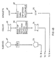
- Fig. 4 is a flow diagram illustration of a shirt manufacturing operation in accordance with the present invention.
- the individual cut elements 61 - 69 are illustrated at the top of the diagram. Below each element are listed in blocks 82 - 87, the operations which are carried out thereon to produce the respective subassemblies 70 - 75. The respective subassemblies are then combined in a final garment 60.
- Horizontal lines 76 - 81 indicate transfers of one element to another. Transfers 78 - 79 can be robot transfers. Operations 82 - 87 are all automatic and can be carried out in accordance with the present invention.
- FIG. 5 - 14 illustrate various embodiments of gripper apparatus useful in the transfer apparatus of the present invention.
- Fig. 5 illustrates a preferred embodiment of the gripper comprising a generally hollow body 100, the interior of which communicates with a tube 102 for connection to a vacuum pump.
- the body 100 defines an operative face 104 having a plurality of holes 105, typically three in number, each fitted with a protruding tubular collar 106, typically formed of rubber. Additionally along one or both edges of the body 100 there may be provided a plurality of smaller holes 107.
- the body 100 is mounted onto a robot arm such that face 104 is downwardly directed, as by means of a mounting element 110, shown in Fig. 6 or a slotted track 112, shown in Fig. 7, or any other suitable mounting means.
- the gripper Upon application of a suitable vacuum to the interior of body 100, the gripper is operative to pick up a piece of cloth which constitutes an individual workpiece.
- the amount of vacuum applied depends on the size and weight of the workpiece sought to be engaged, as well as its composition, the air permeability of its structure and its frictional qualities.
- the vacuum is applied through holes 105 and 107 and the collars 106 tend to reduce sliding of the cloth relative to the gripper.
- the auxiliary holes 107 serve to support the edge of the cloth, which would otherwise tend to hang down and double back over the larger holes.
- Spacer studs 108 serve to space the collars 106 from the cloth and enable the gripper to rest thereon when engaging the cloth. It is appreciated that precise control of the vacuum and of the positioning of the gripper relative to the cloth may obviate the need for spacer studs 108.
- the grippers illustrated in Figs. 5 - 7 having one or more holes may be used individually or may be assembled in arrays to lift relatively larger workpieces. The shape and design of the individual grippers and their orientation and arrangement in a given array may be changed to fit the particular function.
- a plurality of grippers are assembled on a frame 120, as illustrated in Fig. 14.
- the frame 120 is mounted on a robot arm 122 and carries a plurality of individual grippers 124, each associated with a vacuum hose 126 connected to a central vacuum source, not shown.
- the assembly is shown engaging a trouser panel. It is appreciated that the grippers are arranged to control the edges of the panel.
- a given gripper assembly may employ a plurality of grippers, only selected ones of which are employed in any given operation.
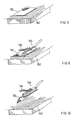
- Figs. 8 - 13 illustrate several operational stages of cloth engagement with the aid of a robot fitted with a gripper according to the present invention.
- a piece of cloth 130 rests in a predetermined orientation on a table 132 ready to be picked up.
- a gripper 134 of the type shown in Fig. 1 mounted at the end of an arm 136 of a robot is caused to bear on cloth 130 while the vacuum is applied.
- the cloth 130 is attached to the gripper 134 and lifted from table 132 as shown in Fig. 10.
- the cloth is transported to another work station 137 fitted with a sewing machine, indicated by foot 138 and needle 140.
- the cloth has been oriented at work station 137 in its precise desired position with respect to the sewing machine foot 138.
- the vacuum is released and the gripper removed from work station 137, the cloth 130 is precisely positioned for processing at the work station.
- gripper apparatus described hereinabove is useful not only for workpiece transfer but also for other functions such as folding of the workpiece.
- the present invention is based on maintaining precise positioning of the workpiece throughout the various processing steps. Through maintenance of precise positioning, control of the individual work stations is simplified.
Landscapes
- Engineering & Computer Science (AREA)
- Textile Engineering (AREA)
- Mechanical Engineering (AREA)
- Sewing Machines And Sewing (AREA)
Priority Applications (2)
| Application Number | Priority Date | Filing Date | Title |
|---|---|---|---|
| US06/731,098 US4756261A (en) | 1985-05-06 | 1985-05-06 | Automatic sewing system and method |
| EP88103901A EP0331787A1 (fr) | 1988-03-11 | 1988-03-11 | Ligne transfert pour couture automatique |
Applications Claiming Priority (1)
| Application Number | Priority Date | Filing Date | Title |
|---|---|---|---|
| EP88103901A EP0331787A1 (fr) | 1988-03-11 | 1988-03-11 | Ligne transfert pour couture automatique |
Publications (1)
| Publication Number | Publication Date |
|---|---|
| EP0331787A1 true EP0331787A1 (fr) | 1989-09-13 |
Family
ID=8198799
Family Applications (1)
| Application Number | Title | Priority Date | Filing Date |
|---|---|---|---|
| EP88103901A Withdrawn EP0331787A1 (fr) | 1985-05-06 | 1988-03-11 | Ligne transfert pour couture automatique |
Country Status (1)
| Country | Link |
|---|---|
| EP (1) | EP0331787A1 (fr) |
Cited By (7)
| Publication number | Priority date | Publication date | Assignee | Title |
|---|---|---|---|---|
| CN102605575A (zh) * | 2011-01-19 | 2012-07-25 | 杨星源 | 无底线的计算机刺绣机 |
| CN106637715A (zh) * | 2017-01-20 | 2017-05-10 | 远东服装(苏州)有限公司 | 一种机械手缝制设备 |
| CN108166170A (zh) * | 2017-12-29 | 2018-06-15 | 杰克缝纫机股份有限公司 | 一种门襟自动校准装置 |
| CN108457008A (zh) * | 2018-03-28 | 2018-08-28 | 杰克缝纫机股份有限公司 | 一种门襟卷缝机 |
| CN114507947A (zh) * | 2022-02-23 | 2022-05-17 | 申洲针织(安徽)有限公司 | 一种自动拷克双针转弯缝制组件及其操作方法 |
| DE102023114965A1 (de) * | 2023-06-07 | 2024-12-12 | Silana Gmbh | Verfahren zum robotergestützten Nähen von mehreren Stofflagen |
| GB2637983A (en) * | 2024-02-09 | 2025-08-13 | Margarita Orozco Pizarro Ella | Compact clothing manufacturing assembly, modules therefor and methods of assembling and using a clothing manufacturing assembly |
Citations (5)
| Publication number | Priority date | Publication date | Assignee | Title |
|---|---|---|---|---|
| US3580198A (en) * | 1969-08-26 | 1971-05-25 | Riegel Textile Corp | Apparatus for automatically fabricating individual articles |
| US3611960A (en) * | 1970-05-11 | 1971-10-12 | Ivanhoe Research Corp | Rotating plate workpiece orienting and point-to-point feeding apparatus |
| DE2145816A1 (de) * | 1971-09-14 | 1973-03-15 | Ivanhoe Research Corp | Verfahren und geraet fuer die automatische herstellung von bekleidungsstuecken |
| DE2640148A1 (de) * | 1976-09-07 | 1978-03-09 | Union Special Gmbh | Stapler fuer von einer naehmaschine abzunehmende stoffteile |
| EP0112116A1 (fr) * | 1982-12-10 | 1984-06-27 | THE SHENKAR COLLEGE OF TEXTILE TECHNOLOGY & FASHION | Preneur à suction pour machines automatiques de traitement de pièces d'étoffe |
-
1988
- 1988-03-11 EP EP88103901A patent/EP0331787A1/fr not_active Withdrawn
Patent Citations (5)
| Publication number | Priority date | Publication date | Assignee | Title |
|---|---|---|---|---|
| US3580198A (en) * | 1969-08-26 | 1971-05-25 | Riegel Textile Corp | Apparatus for automatically fabricating individual articles |
| US3611960A (en) * | 1970-05-11 | 1971-10-12 | Ivanhoe Research Corp | Rotating plate workpiece orienting and point-to-point feeding apparatus |
| DE2145816A1 (de) * | 1971-09-14 | 1973-03-15 | Ivanhoe Research Corp | Verfahren und geraet fuer die automatische herstellung von bekleidungsstuecken |
| DE2640148A1 (de) * | 1976-09-07 | 1978-03-09 | Union Special Gmbh | Stapler fuer von einer naehmaschine abzunehmende stoffteile |
| EP0112116A1 (fr) * | 1982-12-10 | 1984-06-27 | THE SHENKAR COLLEGE OF TEXTILE TECHNOLOGY & FASHION | Preneur à suction pour machines automatiques de traitement de pièces d'étoffe |
Cited By (8)
| Publication number | Priority date | Publication date | Assignee | Title |
|---|---|---|---|---|
| CN102605575A (zh) * | 2011-01-19 | 2012-07-25 | 杨星源 | 无底线的计算机刺绣机 |
| CN106637715A (zh) * | 2017-01-20 | 2017-05-10 | 远东服装(苏州)有限公司 | 一种机械手缝制设备 |
| CN108166170A (zh) * | 2017-12-29 | 2018-06-15 | 杰克缝纫机股份有限公司 | 一种门襟自动校准装置 |
| CN108166170B (zh) * | 2017-12-29 | 2020-06-30 | 杰克缝纫机股份有限公司 | 一种门襟自动校准装置 |
| CN108457008A (zh) * | 2018-03-28 | 2018-08-28 | 杰克缝纫机股份有限公司 | 一种门襟卷缝机 |
| CN114507947A (zh) * | 2022-02-23 | 2022-05-17 | 申洲针织(安徽)有限公司 | 一种自动拷克双针转弯缝制组件及其操作方法 |
| DE102023114965A1 (de) * | 2023-06-07 | 2024-12-12 | Silana Gmbh | Verfahren zum robotergestützten Nähen von mehreren Stofflagen |
| GB2637983A (en) * | 2024-02-09 | 2025-08-13 | Margarita Orozco Pizarro Ella | Compact clothing manufacturing assembly, modules therefor and methods of assembling and using a clothing manufacturing assembly |
Similar Documents
| Publication | Publication Date | Title |
|---|---|---|
| US4756261A (en) | Automatic sewing system and method | |
| CN110158242B (zh) | 缝制装置 | |
| EP0331787A1 (fr) | Ligne transfert pour couture automatique | |
| JPS6080484A (ja) | タイツ形成装置から製品を供給かつ連続自動移送し,タイツの先端部を縫製する方法及び装置 | |
| JP2017196207A (ja) | 縫製システム | |
| US5133444A (en) | Method and apparatus for simultaneous transfer of workpieces between multiple stations | |
| EP0574501B1 (fr) | Appareil de couture et de surjet de parties d'entre-jambes | |
| JPH0117400B2 (fr) | ||
| US20250027243A1 (en) | System for automated manufacturing of garments | |
| CN105803685A (zh) | 边缝缝纫机 | |
| JP2002510215A (ja) | 未加工の閉鎖縁を備えたフラップおよびポケットを一回の工程で縫製物の一部分に縫い付ける方法および自動縫製機 | |
| JPH01242090A (ja) | 自動縫製方法と装置 | |
| US5123367A (en) | Method and apparatus for forming and stacking a folded sewn ply such as a V-top shirt pocket | |
| US3776162A (en) | Method for producing patch pockets on articles of clothing | |
| US5140919A (en) | Method for manufacturing tee shirts from tubular blanks including fastening blanks in registry during finishing steps | |
| CN213946463U (zh) | 袖克夫机器人工作站 | |
| Taylor et al. | Automated handling of fabrics | |
| US5178381A (en) | Processing flexible sheet workpieces | |
| US4714035A (en) | Placket lining machine | |
| CN112518774A (zh) | 袖克夫机器人工作站 | |
| JP2719553B2 (ja) | 自動縫製装置 | |
| JPS6241684A (ja) | 自動組立縫製装置 | |
| EP0190229B1 (fr) | Dispositif de transport et de guidage pour coudre un tissu mou | |
| JPH0647136B2 (ja) | プレス加工用ワーク送給装置 | |
| US4708073A (en) | Method for processing fabric pieces in a cut and sew operation |
Legal Events
| Date | Code | Title | Description |
|---|---|---|---|
| PUAI | Public reference made under article 153(3) epc to a published international application that has entered the european phase |
Free format text: ORIGINAL CODE: 0009012 |
|
| AK | Designated contracting states |
Kind code of ref document: A1 Designated state(s): AT BE CH DE ES FR GB GR IT LI LU NL SE |
|
| STAA | Information on the status of an ep patent application or granted ep patent |
Free format text: STATUS: THE APPLICATION IS DEEMED TO BE WITHDRAWN |
|
| 18D | Application deemed to be withdrawn |
Effective date: 19900314 |