EP0332132A2 - Système servocommande électro-hydraulique notamment pour presses d'injections - Google Patents
Système servocommande électro-hydraulique notamment pour presses d'injections Download PDFInfo
- Publication number
- EP0332132A2 EP0332132A2 EP89103985A EP89103985A EP0332132A2 EP 0332132 A2 EP0332132 A2 EP 0332132A2 EP 89103985 A EP89103985 A EP 89103985A EP 89103985 A EP89103985 A EP 89103985A EP 0332132 A2 EP0332132 A2 EP 0332132A2
- Authority
- EP
- European Patent Office
- Prior art keywords
- pressure
- valve
- control
- function
- signal
- Prior art date
- Legal status (The legal status is an assumption and is not a legal conclusion. Google has not performed a legal analysis and makes no representation as to the accuracy of the status listed.)
- Granted
Links
Images
Classifications
-
- B—PERFORMING OPERATIONS; TRANSPORTING
- B29—WORKING OF PLASTICS; WORKING OF SUBSTANCES IN A PLASTIC STATE IN GENERAL
- B29C—SHAPING OR JOINING OF PLASTICS; SHAPING OF MATERIAL IN A PLASTIC STATE, NOT OTHERWISE PROVIDED FOR; AFTER-TREATMENT OF THE SHAPED PRODUCTS, e.g. REPAIRING
- B29C45/00—Injection moulding, i.e. forcing the required volume of moulding material through a nozzle into a closed mould; Apparatus therefor
- B29C45/17—Component parts, details or accessories; Auxiliary operations
- B29C45/76—Measuring, controlling or regulating
- B29C45/77—Measuring, controlling or regulating of velocity or pressure of moulding material
-
- B—PERFORMING OPERATIONS; TRANSPORTING
- B29—WORKING OF PLASTICS; WORKING OF SUBSTANCES IN A PLASTIC STATE IN GENERAL
- B29C—SHAPING OR JOINING OF PLASTICS; SHAPING OF MATERIAL IN A PLASTIC STATE, NOT OTHERWISE PROVIDED FOR; AFTER-TREATMENT OF THE SHAPED PRODUCTS, e.g. REPAIRING
- B29C45/00—Injection moulding, i.e. forcing the required volume of moulding material through a nozzle into a closed mould; Apparatus therefor
- B29C45/17—Component parts, details or accessories; Auxiliary operations
- B29C45/76—Measuring, controlling or regulating
- B29C45/82—Hydraulic or pneumatic circuits
-
- Y—GENERAL TAGGING OF NEW TECHNOLOGICAL DEVELOPMENTS; GENERAL TAGGING OF CROSS-SECTIONAL TECHNOLOGIES SPANNING OVER SEVERAL SECTIONS OF THE IPC; TECHNICAL SUBJECTS COVERED BY FORMER USPC CROSS-REFERENCE ART COLLECTIONS [XRACs] AND DIGESTS
- Y10—TECHNICAL SUBJECTS COVERED BY FORMER USPC
- Y10T—TECHNICAL SUBJECTS COVERED BY FORMER US CLASSIFICATION
- Y10T137/00—Fluid handling
- Y10T137/7722—Line condition change responsive valves
- Y10T137/7758—Pilot or servo controlled
- Y10T137/7759—Responsive to change in rate of fluid flow
-
- Y—GENERAL TAGGING OF NEW TECHNOLOGICAL DEVELOPMENTS; GENERAL TAGGING OF CROSS-SECTIONAL TECHNOLOGIES SPANNING OVER SEVERAL SECTIONS OF THE IPC; TECHNICAL SUBJECTS COVERED BY FORMER USPC CROSS-REFERENCE ART COLLECTIONS [XRACs] AND DIGESTS
- Y10—TECHNICAL SUBJECTS COVERED BY FORMER USPC
- Y10T—TECHNICAL SUBJECTS COVERED BY FORMER US CLASSIFICATION
- Y10T137/00—Fluid handling
- Y10T137/7722—Line condition change responsive valves
- Y10T137/7758—Pilot or servo controlled
- Y10T137/7761—Electrically actuated valve
Definitions
- the present invention is directed to an electrohydraulic servo system for controlling supply of fluid under pressure to a cavity of unknown volume, and more particularly to a system of the described type for controlling both flow and pressure of hydraulic fluid fed to an injection molding machine.
- electrohydraulic servo systems it is desirable initially to operate the machine injection cylinder in a flow-control mode of operation for controlling flow of fluent plastic into the mold cavity, followed by a pressure-control mode of operation for maintaining desired pressure profile after the cavity is full.
- electrohydraulic systems which employ electronic feedback of system pressure for closed-loop pressure control, problems arise because servo loop gains vary with cavity volume, and because effective cavity volume often varies either by operator intent or because of fluid leaks in the system. Total compression volume, including molten plastic in the mold cavity, may vary by a 12:1 ratio depending upon size and type of mold. However, a volume change as low as 10 to 20 % requires adjustment of servo loop gains to maintain desired performance. In the past, loop gains have been adjusted manually (if at all) on an essentially empirical (trial and error) basis.
- An electrohydraulic servo system for controlling pressure of fluid in a cavity of undetermined volume in accordance with the present invention includes a main valve having a valve element whose position is controlled by pilot fluid pressure, and ports for supplying fluid as a function of position of the valve element within the surrounding valve body.
- a pilot valve is responsive to electronic valve control signals for controlling pilot pressure within the main valve body and thereby controlling position of the valve element.
- An electronic valve controller receives a pressure command signal from remote master electronics as a function of desired fluid pressure within the cavity volume and a pressure feedback signal indicative of fluid pressure within the cavity volume from a pressure sensor coupled to the main valve output ports. The pressure command signal is compared to the pressure feedback signal in a pressure-control mode of operation, and a difference or error signal is employed for generating valve control signals to the pilot valve.
- a second sensor is coupled to the valve element for supplying a position feedback signal as a function of position of the valve element within the surrounding valve body.
- Both the position feedback signal and the pressure feedback signal are employed in the pressure control servo loop, with the pressure feedback signal being varied as a function of a gain Kp, the position feedback signal being varied as a function of a gain Kd, and the difference or error signal being varied as a function of a gain Ke.
- Cavity volume is determined as a function of the pressure and position feedback signals.
- Control loop gains, specifically gains Ke and Kd are varied as a function of cavity volume for thereby adapting the servo control system for either intended or unintended variations in cavity volume.
- valve control electronics comprise a microprocessor-based controller which periodically samples the pressure and position feedback signals, updates loop gains as a function thereof, samples the pressure and flow command inputs, and automatically varies the valve control signal to the electrohydraulic servo valve, in either a flow-control or a pressure-control mode of operation, to obtain desired flow and pressure control at the mold cavity.
- the valve control electronics includes facility for operating the valve initially in a flow-control mode as a function of flow command signals received from remote master electronics for controlling rate of injection of material into the molding machine, and subsequently in a pressure-control mode under control of pressure command signals received from the remote master electronics for maintaining desired pressure profile in the molding machine after the cavity has been filled.
- the servo control electronics includes facility for automatically switching from flow-control to pressure-control mode of operation when increasing cavity pressure, sensed by the pressure sensor at the main valve output, indicates that the injection mold cavity has been filled.
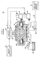
- Fig. 1 illustrates an electrohydraulic servo system 10 in accordance with the present invention for operating the injection ram of a conventional injection molding machine 12.
- System 10 includes a main directional valve 14 in which a spool or a poppet as a valve element 16 is movably mounted within a valve body 18 for controlling application of hydraulic fluid from an input port 20 to one of output ports 24, 26.
- a pump 28 feeds hydraulic fluid from a source 30 to port 20 at a fixed pressure set by a relief valve 29.
- An accumulator (not shown) may be employed to suppress transient pressure fluctuations.
- Output ports 24, 26 are connected to a linear actuator 32 on opposite sides of the actuator piston 34 and one of them forms the return line to a tank port 22 depending upon the position of the directional valve 14.
- Piston 34 is coupled by the shaft 36 to the injection ram (not shown of molding machine 12.
- main valve 14 is configurated as a so-called P-Q valve for controlling flow Q and pressure P of hydraulic fluid to actuator 32, and thus to control velocity of the injector ram and pressure applied thereby within molding machine 12.
- total volume under compression is the volume in the downstream side of valve 14 - i. e. fluid volume within actuator 32 and cavity volume within machine 12.
- An electrohydraulic servo valve 38 or a proportional solenoid valve as a pilot valve is mounted on valve block 18 and is responsive to electronic valve control signals from control electronics 40 for supplying pilot pressure to control the position of valve element 16 within valve body 18.
- Control electronics 40 is mounted in assembly on servo valve 38.
- Control electronics 40 receives command signals from, and transmits suitable operating and status data to, a remote master controller 42.
- a position sensor 44 such as an LVDT transducer, is mounted on a valve body 18 and is coupled to element 16 for providing a feedback signal Y to control electronics 40 indicative of position of element 16 within valve body 18.
- Element 16 is biased to a neutral centered position with body 18 by coil springs 47, 48.
- a second or pressure sensor 46 is coupled to output port 26 (or output port 24, if this port is on working pressure) and provides a feedback signal P to control electronics 40 as a function of valve output fluid pressure.
- servo valve 38 and control electronics 40 take the form of a unitary assembly of the type disclosed in EP 0 240 965 A1.
- Control electronics 40 in such preferred embodiment of the invention comprises a microprocessor-based controller which include facility of receiving, sampling and storing command signals from a master controller 42, and for generating appropriate valve control signals to servo valve 38.
- Control electronics 40 also includes memory having valve control programs and start-up data prestored therein. Such programs are remotely selectable by master controller 42. Start-up data, including loop gain constants, are variable either from master controller 42 or through internal adaptive control programs as will be discussed in detail herinafter.
- An exemplary master controller 42 is disclosed in EP 0 272 397 A2.
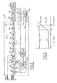
- Fig. 2 is a functional block diagram of system 10 illustrated schematically in Fig. 1, including a detailed functional block diagram of microprocessor-based control electronics 40 in accordance with the present invention.
- electronics 40 is preferably implemented in a microprocessor-based controller of the character disclosed in EP 0 240 965 A1.
- the functional block diagram of control electronics 40 in Fig. 2 illustrates such microprocessor-based controller as configured by suitable control programming.
- microprocessor-based controller includes facility for sampling and storing each of the input signals thereto at periodic sampling intervals. Such sampling circuitry is not illustrated functionally in Fig. 2 for purposes of clarity.
- a pressure command Pc received from master controller 42 (Fig. 1) is fed to the non-inverting input of a summing junction 50 within control electronics 40.
- the output Y of position sensor 44 is fed through an a/d converter 52 and through a feedback compensation network 54 to an inverting input of junction 50.
- the output P of pressure sensor 46 is fed through an a/d converter 56 and through the feedback compensation network 58 to an inverting input of junction 50.
- the rate of change ⁇ of the position feedback signal Y is formed and a modified signal KdxS delivered by multiplying the position feedback signal Y by the gain Kd and by the Laplace character "S", such multiplication being a standard technique for illustrating a differentiation operation.
- output P of pressure sensor 46 is multiplied by the factor (l+KpxS), including the gain Kp and the rate of change ⁇ of pressure signal P.
- the output of junction 50 representing the difference between the pressure command input Pc and the position and pressure feedback signals Y, P varied by respective feedback networks 54, 58, is fed to an integrator 60 where it is multiplied by the gain Ke and divided by the Laplace character "S".
- a gain adjustment network 70 has inputs which receive position feedback Y and pressure feedback P, and outputs coupled to feedback networks 54, 58 and integrator 60 for selectively and adaptively varying gains Kp, Kd and/or Ke as will be described hereafter.
- the output of integrator 60 is fed through a limiting stage 62 to a minimum-selection stage 64.
- Stages 62, 64 also receive as inputs a flow command signal Qc from master controller 42.
- Limiting stage 62 provides an output which is equal to its input from integrator 60 up to a limit corresponding to flow command Qc.
- the output of minimum-select stage 64 which follows the lesser of its inputs, is fed through a gain 66 as a position command signal Yc to a position control servo loop 67 at the non-inverting input of a summing junction 68.
- the inverting input of junction 68 receives position feedback Y from sensor 44.
- the differential output of junction 68 thus indicates position error Ye at valve element 16 (Fig. 1).
- a lead network 72 compensates the position error Ye for operational lag at valves 14, 38 and for lag introduced by the digital sampling process.
- the compensated position error signal is fed through a gain 74, and suitable bais is added to the output.
- the result is fed through a pulse width modulation amplifier 76 to the torque motor of servo valve 38.
- control electronics 40 receives a flow command Qc from master controller 42 indicative of desired rate of fluid flow at output ports 24, 26 of valve 14, a corresponding velocity of piston 34 within actuator 32 and a directly corresponding rate of flow of molten plastic into the cavity of molding machine 12. Likewise, controller 40 receives a pressure command Pc indicative of desired pressure within the mold cavity.
- Control electronics 40 is responsive to command Qc, Pc and to feedback signals Y, P to select between pressure and flow control modes of operation and to feed a corresponding position command Yc to position servo loop 67.
- fluid pressure P is low (Fig. 3) yielding a high output at integrator 60.
- Flow command Qc is therefore selected at stage 64 and fed after suitable gain 66 to junction 68 as position command Yc.
- Position control loop 67 thus controls servo valve 38 and valve 14 for obtaining constant position Y (Fig. 3) of element 16 (Fig. 1), corresponding to a constant desired flow rate Qc.
- pressure ⁇ is differential (Kp x S) and added to itself.
- V x (dP / dt) B x Q(t) (1) where V is cavity volume and B is effective bulk modulus of the hydraulic fluid and molten plastic.
- Equation (2) assumes, as a first order approximation, that metering area of valve 14 is proportional to spool travel from center. Spool position Y is constant (Fig. 3) as pressure increases until controller 40 switches from flow-control to pressure-control mode of operation.
- SQRT(Ps-P1) is a constant which may be obtained by evaluating the solution of equation (3) at time t1 in Fig. 3 where pressure P is equal to P1 and position Y is equal to Y1.
- V K/2 x (N x T x (Y-Yz)) / (SQRT(Ps-P1) - SQRT(Ps-P2)) (4)
- Actual cavity volume V is thus determinated.
- average position (Y1+Y2)/2 may be employed in equation (4).
Landscapes
- Engineering & Computer Science (AREA)
- Manufacturing & Machinery (AREA)
- Mechanical Engineering (AREA)
- Injection Moulding Of Plastics Or The Like (AREA)
- Servomotors (AREA)
- Fluid-Pressure Circuits (AREA)
Applications Claiming Priority (2)
| Application Number | Priority Date | Filing Date | Title |
|---|---|---|---|
| US07/164,957 US4798527A (en) | 1988-03-07 | 1988-03-07 | Control system for injection molding machine |
| US164957 | 1988-03-07 |
Publications (3)
| Publication Number | Publication Date |
|---|---|
| EP0332132A2 true EP0332132A2 (fr) | 1989-09-13 |
| EP0332132A3 EP0332132A3 (fr) | 1991-04-17 |
| EP0332132B1 EP0332132B1 (fr) | 1993-09-29 |
Family
ID=22596818
Family Applications (1)
| Application Number | Title | Priority Date | Filing Date |
|---|---|---|---|
| EP89103985A Expired - Lifetime EP0332132B1 (fr) | 1988-03-07 | 1989-03-07 | Système servocommande électro-hydraulique notamment pour presses d'injections |
Country Status (8)
| Country | Link |
|---|---|
| US (1) | US4798527A (fr) |
| EP (1) | EP0332132B1 (fr) |
| JP (1) | JP2923299B2 (fr) |
| CN (1) | CN1023196C (fr) |
| AU (1) | AU603284B2 (fr) |
| CA (1) | CA1305644C (fr) |
| DE (1) | DE68909450T2 (fr) |
| ES (1) | ES2045221T3 (fr) |
Cited By (2)
| Publication number | Priority date | Publication date | Assignee | Title |
|---|---|---|---|---|
| EP0722134A1 (fr) * | 1995-01-12 | 1996-07-17 | MAC Valves Inc. | Méthode et installation de vannes pour la régulation d'un signal pilote |
| WO2002046624A3 (fr) * | 2000-12-05 | 2002-12-12 | Bosch Gmbh Robert | Procede permettant de faire fonctionner un dispositif de regulation d'un systeme hydraulique |
Families Citing this family (23)
| Publication number | Priority date | Publication date | Assignee | Title |
|---|---|---|---|---|
| DE3734955A1 (de) * | 1987-10-15 | 1989-04-27 | Rexroth Mannesmann Gmbh | Elektrische messwertaufbereitung fuer ein regelventil |
| US5042530A (en) * | 1989-04-25 | 1991-08-27 | Hydril Company | Subsea wellhead apparatus |
| US4979639A (en) * | 1989-05-23 | 1990-12-25 | The Coca-Cola Company | Beverage dispenser control valve and ratio control method therefor |
| US5101862A (en) * | 1991-08-08 | 1992-04-07 | Leete Barrett C | Rotary actuator and valve control system |
| FR2738613B1 (fr) * | 1995-09-08 | 1997-10-24 | Thomson Csf | Procede d'asservissement d'une servovalve hydraulique pouvant etre asservie en debit et en pression |
| DE19603012C1 (de) * | 1996-01-18 | 1997-09-04 | Mannesmann Ag | Plastifizier- und Einspritzeinheit einer Kunststoffspritzgießmaschine |
| CA2292279A1 (fr) | 1998-12-18 | 2000-06-18 | Fluoroware, Inc. | Soupape resistant a une charge statique continue |
| US7293910B2 (en) * | 2001-05-24 | 2007-11-13 | Masco Corporation | Surge suppressor for a mixer head assembly |
| US7077290B2 (en) * | 2002-05-17 | 2006-07-18 | Pepsico, Inc. | Beverage forming and dispensing system |
| US8056579B2 (en) * | 2007-06-04 | 2011-11-15 | Horiba Stec, Co., Ltd. | Mass flow controller |
| US8033808B2 (en) * | 2007-08-24 | 2011-10-11 | Delta Pt, Llc | Pressure compensating molding system |
| DE102008028190A1 (de) * | 2008-06-12 | 2009-12-17 | Abb Technology Ag | Verfahren zum Betrieb eines elektropneumatischen Ventils |
| DE102008028192A1 (de) * | 2008-06-12 | 2009-12-17 | Abb Technology Ag | Elektropneumatisches Ventil |
| DE102009004571A1 (de) * | 2009-01-14 | 2010-07-22 | Abb Technology Ag | Verfahren und elektronische Einrichtung zum Prüfen von Ansteuerparametern eines elektro-pneumatischen Ventils bei einem pneumatischen Stellantrieb |
| GB0908982D0 (en) * | 2009-05-26 | 2009-07-01 | David Brown Hydraulics Ltd | Controlled hydraulic systems |
| KR20140034211A (ko) | 2011-05-26 | 2014-03-19 | 이턴 코포레이션 | 통합 센서를 갖는 밸브 어셈블리 |
| DE102012109206B4 (de) * | 2011-11-30 | 2019-05-02 | Hanon Systems | Ventil-Sensor-Anordnung |
| CN102729442B (zh) * | 2012-07-04 | 2015-01-07 | 宁波巴斯顿机械科技有限公司 | 一种高精度高速闭环控制氮气辅助射胶注塑机 |
| CN104571201A (zh) * | 2014-12-31 | 2015-04-29 | 李久伦 | 三相电多通道温控器 |
| CN104552855A (zh) * | 2014-12-31 | 2015-04-29 | 李久伦 | 三相电多通道电压控制器 |
| CN104571200A (zh) * | 2014-12-31 | 2015-04-29 | 李久伦 | 三相电多通道控制器 |
| CN104597941A (zh) * | 2014-12-31 | 2015-05-06 | 李久伦 | 热流道温度控制系统主控器 |
| CN109878045B (zh) * | 2019-01-31 | 2020-12-29 | 贵州省材料产业技术研究院 | 智能调节模具型腔压力恒定与精准控制的控制装置 |
Family Cites Families (19)
| Publication number | Priority date | Publication date | Assignee | Title |
|---|---|---|---|---|
| FR2088571A5 (fr) * | 1970-04-17 | 1972-01-07 | Serea | |
| US3941534A (en) * | 1971-11-01 | 1976-03-02 | Hunkar Laboratories, Inc. | Injection molding control system |
| US3767339A (en) * | 1971-11-01 | 1973-10-23 | Hunkar Instr Dev Labor Inc | Injection molding control |
| JPS48114573U (fr) * | 1972-04-03 | 1973-12-27 | ||
| CH554741A (de) * | 1973-02-07 | 1974-10-15 | Netstal Ag Maschf Giesserei | Kunststoff-spritzgiessmaschine mit programmiereinrichtung. |
| US3920367A (en) * | 1973-05-10 | 1975-11-18 | Cincinnati Milacron Inc | Mold pressure control apparatus |
| US4161380A (en) * | 1974-10-21 | 1979-07-17 | Hpm Corporation | Injection molding process control |
| DE2523600A1 (de) * | 1975-05-28 | 1976-12-09 | Bosch Gmbh Robert | Elektrohydraulische steuereinrichtung |
| GB1518720A (en) * | 1975-11-21 | 1978-07-26 | Ishikawajima Harima Heavy Ind | Hydraulic servomechanism |
| JPS5722564Y2 (fr) * | 1975-11-26 | 1982-05-17 | ||
| CH642905A5 (de) * | 1979-07-16 | 1984-05-15 | Netstal Ag Maschf Giesserei | Spritzgiessmaschine. |
| JPS56146741A (en) * | 1980-04-18 | 1981-11-14 | Hitachi Ltd | Setting of holding time and system therefor |
| FR2511638A1 (fr) * | 1981-08-21 | 1983-02-25 | Marcel Manceau | Procede de modulation de pression d'injection |
| US4456031A (en) * | 1982-05-03 | 1984-06-26 | Vickers, Incorporated | Electro-hydraulic servo valve system |
| DE3319268C1 (de) * | 1983-05-27 | 1984-09-13 | Klöckner-Werke AG, 4100 Duisburg | Regelvorrichtung fuer die Bewegung einer hydraulisch verschiebbaren Formaufspannplatte einer Spritzgiessmaschine |
| JPS60154028A (ja) * | 1984-01-23 | 1985-08-13 | Toshiba Mach Co Ltd | 射出成形機の射出工程制御方法 |
| DE3447709C1 (de) * | 1984-12-28 | 1986-04-30 | Karl 7298 Loßburg Hehl | Steuervorrichtung fuer den hydraulischen Kreislauf einer Kunststoff-Spritzgiessmaschine |
| JPH0661810B2 (ja) * | 1985-12-26 | 1994-08-17 | 日精樹脂工業株式会社 | 流体圧アクチュエ−タの制御装置 |
| JPS62170318A (ja) * | 1986-01-21 | 1987-07-27 | 北所 重二 | 射出成形装置 |
-
1988
- 1988-03-07 US US07/164,957 patent/US4798527A/en not_active Expired - Lifetime
-
1989
- 1989-02-13 AU AU29867/89A patent/AU603284B2/en not_active Ceased
- 1989-03-03 CA CA000592716A patent/CA1305644C/fr not_active Expired - Fee Related
- 1989-03-06 JP JP1053585A patent/JP2923299B2/ja not_active Expired - Lifetime
- 1989-03-07 DE DE89103985T patent/DE68909450T2/de not_active Expired - Fee Related
- 1989-03-07 CN CN89101213A patent/CN1023196C/zh not_active Expired - Fee Related
- 1989-03-07 EP EP89103985A patent/EP0332132B1/fr not_active Expired - Lifetime
- 1989-03-07 ES ES89103985T patent/ES2045221T3/es not_active Expired - Lifetime
Cited By (2)
| Publication number | Priority date | Publication date | Assignee | Title |
|---|---|---|---|---|
| EP0722134A1 (fr) * | 1995-01-12 | 1996-07-17 | MAC Valves Inc. | Méthode et installation de vannes pour la régulation d'un signal pilote |
| WO2002046624A3 (fr) * | 2000-12-05 | 2002-12-12 | Bosch Gmbh Robert | Procede permettant de faire fonctionner un dispositif de regulation d'un systeme hydraulique |
Also Published As
| Publication number | Publication date |
|---|---|
| EP0332132A3 (fr) | 1991-04-17 |
| CN1023196C (zh) | 1993-12-22 |
| DE68909450D1 (de) | 1993-11-04 |
| JP2923299B2 (ja) | 1999-07-26 |
| CA1305644C (fr) | 1992-07-28 |
| JPH01283401A (ja) | 1989-11-15 |
| AU2986789A (en) | 1989-09-07 |
| AU603284B2 (en) | 1990-11-08 |
| DE68909450T2 (de) | 1994-04-21 |
| CN1038966A (zh) | 1990-01-24 |
| US4798527A (en) | 1989-01-17 |
| ES2045221T3 (es) | 1994-01-16 |
| EP0332132B1 (fr) | 1993-09-29 |
Similar Documents
| Publication | Publication Date | Title |
|---|---|---|
| EP0332132B1 (fr) | Système servocommande électro-hydraulique notamment pour presses d'injections | |
| US5179836A (en) | Hydraulic system for a differential piston type cylinder | |
| US8726646B2 (en) | Hydraulic system having multiple actuators and an associated control method | |
| US4559991A (en) | Method and system of controlling injection molding machines | |
| US4741159A (en) | Power transmission | |
| US5289388A (en) | Electrohydraulic control of a die casting machine | |
| US4708596A (en) | Device for regulating pressure and delivery of and adjustable pump | |
| HK99892A (en) | Hydraulic device for the injection unit of a plastic material injection-moulding machine | |
| US6629558B2 (en) | Die-casting machine | |
| US5634334A (en) | Hydraulic device for use in a production machine | |
| US5513971A (en) | Hydraulic control circuit for an injection molding machine | |
| GB2099610A (en) | A control device for the hydraulic circuit of an injection moulding machine | |
| JP2788675B2 (ja) | 型開閉制御装置 | |
| US4488589A (en) | Shot cylinder controller | |
| US4970885A (en) | Tube bending apparatus | |
| EP0372899A1 (fr) | Procédé et dispositif de commande simultanée de deux ou plusieurs variables dépendantes | |
| US6682332B2 (en) | Dual isolated mode controller for injection molding machine | |
| US5079989A (en) | Electrohydraulic valve system with a pressure feedback signal modulated by a velocity feedback signal when the velocity exceeds a veloity limit | |
| JPH0970700A (ja) | 油圧プレス装置の圧力制御方法並びにその制御装置 | |
| JPH06297128A (ja) | 射出シリンダの制御方法並びにその装置 | |
| EP1417087B1 (fr) | Controleur a deux modes separes pour machine de moulage par injection | |
| JPH0525870Y2 (fr) | ||
| JPH10288203A (ja) | 油圧駆動系の制御方式 | |
| JPH0366522B2 (fr) |
Legal Events
| Date | Code | Title | Description |
|---|---|---|---|
| PUAI | Public reference made under article 153(3) epc to a published international application that has entered the european phase |
Free format text: ORIGINAL CODE: 0009012 |
|
| AK | Designated contracting states |
Kind code of ref document: A2 Designated state(s): DE ES FR GB IT SE |
|
| PUAL | Search report despatched |
Free format text: ORIGINAL CODE: 0009013 |
|
| AK | Designated contracting states |
Kind code of ref document: A3 Designated state(s): DE ES FR GB IT SE |
|
| 17P | Request for examination filed |
Effective date: 19911001 |
|
| 17Q | First examination report despatched |
Effective date: 19930324 |
|
| GRAA | (expected) grant |
Free format text: ORIGINAL CODE: 0009210 |
|
| AK | Designated contracting states |
Kind code of ref document: B1 Designated state(s): DE ES FR GB IT SE |
|
| ITF | It: translation for a ep patent filed | ||
| REF | Corresponds to: |
Ref document number: 68909450 Country of ref document: DE Date of ref document: 19931104 |
|
| ET | Fr: translation filed | ||
| REG | Reference to a national code |
Ref country code: ES Ref legal event code: FG2A Ref document number: 2045221 Country of ref document: ES Kind code of ref document: T3 |
|
| PGFP | Annual fee paid to national office [announced via postgrant information from national office to epo] |
Ref country code: FR Payment date: 19940210 Year of fee payment: 6 |
|
| PGFP | Annual fee paid to national office [announced via postgrant information from national office to epo] |
Ref country code: SE Payment date: 19940215 Year of fee payment: 6 |
|
| PGFP | Annual fee paid to national office [announced via postgrant information from national office to epo] |
Ref country code: GB Payment date: 19940225 Year of fee payment: 6 |
|
| PGFP | Annual fee paid to national office [announced via postgrant information from national office to epo] |
Ref country code: ES Payment date: 19940311 Year of fee payment: 6 |
|
| PLBE | No opposition filed within time limit |
Free format text: ORIGINAL CODE: 0009261 |
|
| STAA | Information on the status of an ep patent application or granted ep patent |
Free format text: STATUS: NO OPPOSITION FILED WITHIN TIME LIMIT |
|
| 26N | No opposition filed | ||
| EAL | Se: european patent in force in sweden |
Ref document number: 89103985.1 |
|
| PG25 | Lapsed in a contracting state [announced via postgrant information from national office to epo] |
Ref country code: GB Effective date: 19950307 |
|
| PG25 | Lapsed in a contracting state [announced via postgrant information from national office to epo] |
Ref country code: SE Effective date: 19950308 Ref country code: ES Free format text: LAPSE BECAUSE OF NON-PAYMENT OF DUE FEES Effective date: 19950308 |
|
| GBPC | Gb: european patent ceased through non-payment of renewal fee |
Effective date: 19950307 |
|
| PG25 | Lapsed in a contracting state [announced via postgrant information from national office to epo] |
Ref country code: FR Free format text: LAPSE BECAUSE OF NON-PAYMENT OF DUE FEES Effective date: 19951130 |
|
| EUG | Se: european patent has lapsed |
Ref document number: 89103985.1 |
|
| REG | Reference to a national code |
Ref country code: FR Ref legal event code: ST |
|
| PGFP | Annual fee paid to national office [announced via postgrant information from national office to epo] |
Ref country code: DE Payment date: 19970225 Year of fee payment: 9 |
|
| PG25 | Lapsed in a contracting state [announced via postgrant information from national office to epo] |
Ref country code: DE Free format text: LAPSE BECAUSE OF NON-PAYMENT OF DUE FEES Effective date: 19981201 |
|
| REG | Reference to a national code |
Ref country code: ES Ref legal event code: FD2A Effective date: 19990405 |
|
| PG25 | Lapsed in a contracting state [announced via postgrant information from national office to epo] |
Ref country code: IT Free format text: LAPSE BECAUSE OF NON-PAYMENT OF DUE FEES;WARNING: LAPSES OF ITALIAN PATENTS WITH EFFECTIVE DATE BEFORE 2007 MAY HAVE OCCURRED AT ANY TIME BEFORE 2007. THE CORRECT EFFECTIVE DATE MAY BE DIFFERENT FROM THE ONE RECORDED. Effective date: 20050307 |