EP0332489B1 - Stellvorrichtung für ein Eisenbahnfahrzeug auf einer Raddrehbank - Google Patents
Stellvorrichtung für ein Eisenbahnfahrzeug auf einer Raddrehbank Download PDFInfo
- Publication number
- EP0332489B1 EP0332489B1 EP89400474A EP89400474A EP0332489B1 EP 0332489 B1 EP0332489 B1 EP 0332489B1 EP 89400474 A EP89400474 A EP 89400474A EP 89400474 A EP89400474 A EP 89400474A EP 0332489 B1 EP0332489 B1 EP 0332489B1
- Authority
- EP
- European Patent Office
- Prior art keywords
- rollers
- carriage
- wheel
- clutch
- rail
- Prior art date
- Legal status (The legal status is an assumption and is not a legal conclusion. Google has not performed a legal analysis and makes no representation as to the accuracy of the status listed.)
- Expired - Lifetime
Links
- 238000006073 displacement reaction Methods 0.000 claims abstract description 5
- 230000005540 biological transmission Effects 0.000 claims description 6
- 238000004804 winding Methods 0.000 claims description 6
- 230000010355 oscillation Effects 0.000 claims description 5
- 230000002441 reversible effect Effects 0.000 claims 1
- 230000001419 dependent effect Effects 0.000 abstract 1
- 238000009434 installation Methods 0.000 description 6
- 241001417494 Sciaenidae Species 0.000 description 2
- 238000003754 machining Methods 0.000 description 2
- 238000005096 rolling process Methods 0.000 description 2
- 230000000903 blocking effect Effects 0.000 description 1
Images


Classifications
-
- B—PERFORMING OPERATIONS; TRANSPORTING
- B23—MACHINE TOOLS; METAL-WORKING NOT OTHERWISE PROVIDED FOR
- B23B—TURNING; BORING
- B23B5/00—Turning-machines or devices specially adapted for particular work; Accessories specially adapted therefor
- B23B5/28—Turning-machines or devices specially adapted for particular work; Accessories specially adapted therefor for turning wheels or wheel sets or cranks thereon, i.e. wheel lathes
- B23B5/32—Turning-machines or devices specially adapted for particular work; Accessories specially adapted therefor for turning wheels or wheel sets or cranks thereon, i.e. wheel lathes for reconditioning wheel sets without removing same from the vehicle; Underfloor wheel lathes for railway vehicles
Definitions
- the present invention relates to the reprofiling of the wheels of a railway vehicle and more specifically to a device carrying out the installation of a railway vehicle on the lathe to be reprofiled and the rotation of the wheels during the reprofiling.
- the use of a railway vehicle gradually causes wear of the wheel treads, due to contact with the rails. This wear is generally not evenly distributed over the periphery of the tread table, and it is necessary, periodically, to reprofile the wheel.
- the reprofiling is carried out by machining the tire tread profiles on the vehicle, without removing the axles, using a pit lathe.
- the reprofiling lathe is a lathe operating in the conventional manner, the turning axis being an axis materialized by the bearings of the axle bearing boxes and kept fixed during turning.
- the rotation of the wheel to be reprofiled around this axis is ensured by two drive rollers, applied to the rolling table of the wheel, on either side of the turning tool.
- US Pat. No. 3,203,286 has already proposed a improved device for positioning a rail vehicle on a wheel reprofiling lathe which includes, for each wheel, two drive rollers and a passing rail in three movable sections: the central section is movable vertically under the action of a hydraulic cylinder, and the two lateral sections are mounted on a carriage supporting the two drive rollers, said carriage being transversely movable.
- the operation of this known device is as follows. The railway vehicle is brought onto the passing rail and is placed so that the wheel is in line with the central section. Under the action of the jack, the central section is lifted and lifts the wheel. Then the carriage advances so that the drive rollers are in position under the wheel. The central section is lowered and the wheel comes into contact with the drive rollers.
- This device therefore comprises independent means, suitable for lifting the wheel during the positioning of the drive rollers.
- the device comprises in known manner, for each wheel, a carriage sliding transversely and supporting two drive rollers and a portion of passage rail.
- the invention comprises support means and an oscillating arm secured to the carriage and on which are mounted the two rollers and the rail portion of the vehicle passage, and in that the vehicle being propped up by the means supporting the carriage slides between a first position where, the swing arm being in the high position and the portion of the passage rail retracted, the two rollers are in contact with the corresponding wheel and a second position where, the swing arm being in position low and the rollers retracted, the wheel is supported by the passage rail portion.
- the rail portion which ensures the positioning of the vehicle above the pit and its removal, is in one piece and forms an integral part of the device for rotating the wheels, and the retraction of this portion of rail is done by oscillation of the swing arm.
- the respective movements of the swing arm and of the sliding carriage are coordinated: the first position of the carriage, for which the drive rollers are in contact with the corresponding wheel, occurs only when the swing arm is in the position second, for which the rail passage portion of the vehicle is retracted; conversely, the first position of the swinging arm, for which the rail supports the vehicle, only intervenes when the sliding carriage is in its second position, for which the drive rollers are retracted.
- the vehicle is placed above the pit on the passage rail, it is then held in height by supports, placed for example under the bearing boxes. It is only after this blocking operation that the passage rail can be retracted.
- This arrangement makes it easy to adjust the pressure exerted by the drive rollers on the corresponding wheel, by acting on the means of oscillation of the arm, for example a hydraulic cylinder.
- the two drive rollers are fixed to the double end of the swinging arm and the portion of the passage rail is fixed to the upper part of the arm between the oscillation axis and the rollers.
- the device for positioning a rail vehicle on a wheel reprofiling lathe comprises a hauling system, the reel drum of which is part of the system for transmitting the rotation of the rollers, said transmission system being provided with two reverse-acting clutches, one for engaging the roller transmission and the other for engaging the take-up drum.
- the rotation system drives either the rollers or the take-up drum.
- the rotation system comprises a drive pulley, a first clutch between the drive pulley and the connecting axis causing the rotation of the rollers, a second clutch between the drive pulley and the system drum hauling, the choice of the clutch of the drive pulley being controlled by the transverse position of the carriage, so that it is engaged on the take-up drum when the carriage is in its second position where the passage rail is in position to support the vehicle and it is engaged on the connecting axis when the carriage is in its first position where the rollers are in contact with the wheel.
- the hauling system integrated into the positioning device, it is the same power element which is used both for hauling and for driving the wheels by the rollers.
- the hauling itself is carried out by any conventional means, using a winch or capstan.
- the device is equipped with a pusher, integral with the connection axis causing the rotation of the rollers, and the movement of the carriage causes the displacement of said connection axis between the second position where the axis is disengaged from the pulley and where a spring maintains the clutch of the drum in the engaged position, and the first position where the axis is engaged on the pulley and where the pusher maintains the clutch of the take-up drum in the disengaged position, the clutch spring being compressed.
- Each wheel 11 of the rail vehicle wears out during use: this wear gradually appears by a generally non-regular deformation of the tread 12, that is to say of the area of the wheel which is in contact with the rail. Reshaping consists in rectifying the tread 12 so that at this location the wheel has the same diameter. For this, the machining tool 13 attacks the tread 12 while the wheel 11 is rotated by the two rollers 14, until the optimum diameter is reached.
- the description which will be given relates only to the part of the device aimed at reprofiling a wheel 11.
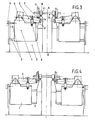
- the device comprises, as shown in FIGS. 3 and 4, a part which is symmetrical with respect to the central axis. AA ′ of the track.
- the carriage 1 supports at its upper part two arms 5 by means of bearings 4.
- Each arm 5 can oscillate around the axis of the bearing 4 thanks to the displacement of the end opposite to the bearing 4 under the action of the jack 6.
- Each arm 5 has at its end oscillating a roller 14 for driving the wheel 11.
- Each roller 14 is rotated, as will be explained later.
- On the upper part of the two arms 5 is fixed a portion of rail 7, the length of which is determined as a function of that of the pit.
- the installation of the rail vehicle on the pit is carried out as follows. Before the vehicle is brought in, the arms 5 are in the low position, the rod of the jack 6 being retracted and the lower part of the arm 5 being in abutment on the wedge 10; the carriage 1 is in the advanced position, the rod of the jack 9 being extended. In these arrangements, the portion of the rail 7 is exactly in alignment with the ends of the rails 15 of the vehicle supply path.
- the two preceding sequences are repeated in the opposite direction so as first to release the rollers 14 from the tread 12 (swing arms 5 in the low position) then to position the portion 7 of passage rail under the wheel 11 (carriage 1 in the advanced position).
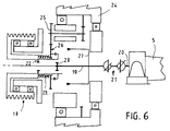
- the positioning and removal of the vehicle, the wheels of which are to be reprofiled on the portion 7 of the passing rail, are carried out by means of the integrated hauling system, as shown in FIGS. 5 and 6.
- the pulley 18 drives the rollers 14 thanks to the transmission system comprising two connecting axes 19 and 20, connected together by the gimbal 21, the first axis 19 being horizontal, while the second axis 20 can follow thanks to the gimbal 21 the up and down oscillations of the arms 5.
- the connecting axes 19 and 20 are integral with the carriage 1, and the end 28 of the first axis 19 is opposite d a first clutch 22, so that the transverse movement of the carriage 1 causes the axes 19 and 20 to move, and the first clutch 22 to be engaged or disengaged on the pulley 18.
- the winding drum 24 of the hauling system is mounted coaxial with the first axis 19, and comprises a drive wheel 25.
- the pulley 18 is equipped with a second clutch 26, accompanied by a spring 23.
- a push arm 27 is fixed to the first axis 19.
- the drive by the pulley 18 of the rollers 14 or of the drum 24 is carried out under the following conditions.
- the carriage 1 When the carriage 1 is in the retracted position, that is to say when the rollers 14 are applied to the tread 12 (reprofiling position), the end 28 of the first connecting axis 19 is engaged in the clutch 22 and the rotation of the pulley 18 rotates the axes 19 and 20 and the rollers 14.
- the push arm 27 pushes the clutch 26 out of the field of the drive wheel 25 of the drum 24, the spring 23 being compressed; the drum 24 is not rotated.
Landscapes
- Engineering & Computer Science (AREA)
- Mechanical Engineering (AREA)
- Turning (AREA)
- Vehicle Cleaning, Maintenance, Repair, Refitting, And Outriggers (AREA)
- Machines For Laying And Maintaining Railways (AREA)
Claims (5)
- Stellvorrichtung für ein Eisenbahnfahrzeug auf einer Raddrehbank zum erneuten Profilieren der Räder, von der Art, die für jedes Rad einen Schlitten (1) aufweist, der in Querrichtung gleitbeweglich und zwei Antriebsrollen (14) trägt, und einen Laufschienenabschnitt (7) aufweist, dadurch gekennzeichnet, daß sie Abstützeinrichtungen (8) und einen hin- und hergehenden Arm (5) aufweist, der mit dem Schlitten (4) verbunden ist, und auf dem die zwei Rollen (14) und der Laufschienenabschnitt (7) des Fahrzeugs angebracht sind, und daß, wenn das Fahrzeug in der Höhe durch die Andruckeinrichtungen (8) eingekeilt ist, der Schlitten (1) zwischen einer ersten Stellung, wo, wenn sich der hin- und hergehende Arm (5) in seiner oberen Stellung befindet und der Laufschienenabschnitt (7) eingefahren ist, die beiden Rollen (14) in Kontakt sind mit dem entsprechenden Rad (11), und einer zweiten Stellung gleitet, wo, wenn sich der hin- und hergehende Arm (5) in seiner unteren Stellung befindet und die Rollen (14) eingefahren sind, das Rad (11) durch den Laufschienenabschnitt (7) abgestützt wird.
- Vorrichtung nach Anspruch 1, dadurch gekennzeichnet, daß die beiden Antriebsrollen (14) am doppelten Ende des hin- und hergehenden Armes (5) befestigt sind und der Laufschienenabschnitt (7) an dem oberen Bereich des Armes (5) zwischen der Schwenkachse und den Rollen (14) befestigt ist.
- Vorrichtung nach Anspruch 1 oder 2, dadurch gekennzeichnet, daß sie ein Schleppsystem aufweist, dessen Aufwickeltrommel (24) Teil des Übertragungssystems der Drehung der Rollen ist, wobei das Übertragungssystem mit zwei Kupplungen (22, 26) mit umgekehrter Wirkung versehen ist, die eine, um die Übertragung der Rollen (14) zu kuppeln, und die andere, um die Aufwickeltrommel (24) zu kuppeln.
- Vorrichtung nach Anspruch 3, dadurch gekennzeichnet, daß das Drehsystem eine Antriebsrolle (18), eine erste Kupplung (22) zwischen der Antriebsrolle und der Verbindungsachse (19), die die Drehung der Rollen (14) erzeugt, und eine zweite Kupplung (26) zwischen der Antriebsrolle (18) und der Aufwickelrolle (24) des Schleppsystems aufweist, wobei die Wahl des Kuppelns der Antriebsrolle (18) gesteuert wird durch die Querstellung des Schlittens (1), derart, daß es mit der Aufwickelrolle (24) eingerückt ist, wenn der Schlitten (1) sich in seiner zweiten Stellung befindet, wo der Laufschienenabschnitt (7) in der Stellung ist, daß er das Rad (11) stützt, und daß sie eingerückt ist mit der Verbindungsachse (19), wenn der Schlitten (1) sich in seiner ersten Stellung befindet, wo die Rollen (14) mit dem Rad (11) in Berührung sind.
- Vorrichtung nach Anspruch 4, dadurch gekennzeichnet, daß sie mit einem Drücker (27) ausgerüstet ist, der mit der Verbindungsachse (19) verbunden ist, die die Rollen (14) in Drehung versetzt, und daß die Bewegung des Schlittens (1) die Bewegung der Verbindungsachse (19) zwischen der zweiten Stellung, wo die Achse (19) von der Rolle (18) abgekoppelt ist, und wo eine Feder (23) die Kupplung (26) der Trommel (24) in eingerückter Stellung hält, und der ersten Stellung hervorruft, wo die Achse (19) mit der Rolle (18) eingekuppelt ist, und wo der Drücker (27) die Kupplung (26) der Aufwickeltrommel (24) in ausgekuppelter Stellung hält, wobei die Kupplungsfeder (23) komprimiert ist.
Priority Applications (1)
| Application Number | Priority Date | Filing Date | Title |
|---|---|---|---|
| AT89400474T ATE84996T1 (de) | 1988-02-25 | 1989-02-21 | Stellvorrichtung fuer ein eisenbahnfahrzeug auf einer raddrehbank. |
Applications Claiming Priority (2)
| Application Number | Priority Date | Filing Date | Title |
|---|---|---|---|
| FR8802819 | 1988-02-25 | ||
| FR888802819A FR2627716B1 (fr) | 1988-02-25 | 1988-02-25 | Dispositif de mise en place d'un vehicule ferroviaire sur un tour a reprofiler les roues |
Publications (2)
| Publication Number | Publication Date |
|---|---|
| EP0332489A1 EP0332489A1 (de) | 1989-09-13 |
| EP0332489B1 true EP0332489B1 (de) | 1993-01-27 |
Family
ID=9363938
Family Applications (1)
| Application Number | Title | Priority Date | Filing Date |
|---|---|---|---|
| EP89400474A Expired - Lifetime EP0332489B1 (de) | 1988-02-25 | 1989-02-21 | Stellvorrichtung für ein Eisenbahnfahrzeug auf einer Raddrehbank |
Country Status (4)
| Country | Link |
|---|---|
| EP (1) | EP0332489B1 (de) |
| AT (1) | ATE84996T1 (de) |
| DE (1) | DE68904577T2 (de) |
| FR (1) | FR2627716B1 (de) |
Cited By (1)
| Publication number | Priority date | Publication date | Assignee | Title |
|---|---|---|---|---|
| RU2445221C2 (ru) * | 2006-06-26 | 2012-03-20 | Евромэйнт АБ | Устройство для подъема по меньшей мере одного колеса рельсового транспортного средства |
Families Citing this family (6)
| Publication number | Priority date | Publication date | Assignee | Title |
|---|---|---|---|---|
| DE4006667A1 (de) * | 1990-03-03 | 1991-09-12 | Hoesch Maschinenfabrik Ag | Unterflur-radsatzdrehmaschine zum reprofilieren der raeder von eisenbahn-radsaetzen |
| RU2126313C1 (ru) * | 1998-05-06 | 1999-02-20 | Сибирская государственная академия путей сообщения | Станок для обточки колесных пар |
| RU2159166C2 (ru) * | 1999-02-15 | 2000-11-20 | Сибирский государственный университет путей сообщения | Станок для обточки колесных пар |
| EP2161177B1 (de) | 2008-09-09 | 2011-11-02 | EuroMaint AB | Hebevorrichtung |
| DE202010007239U1 (de) * | 2010-05-24 | 2010-09-16 | Hegenscheidt-Mfd Gmbh & Co. Kg | Unterflurradsatzdrehmaschine |
| EP3819050A1 (de) | 2019-11-05 | 2021-05-12 | Sogema Engineering | Modulare und tragbare unterflurdrehbank |
Family Cites Families (4)
| Publication number | Priority date | Publication date | Assignee | Title |
|---|---|---|---|---|
| DE1402955A1 (de) * | 1960-11-24 | 1968-10-31 | Hegenscheidt Kg Wilhelm | Unterflur-Profildrehmaschine fuer die Bearbeitung der Umrisse nicht ausgebundener Radsaetze |
| DE1605334B2 (de) * | 1967-08-03 | 1976-02-05 | Hoesch Maschinenfabrik Deutschland Ag, 4600 Dortmund | Verfahren und anordnung zum vermessen und reprofilieren von in schienenfahrzeugen eingebauten radsaetzen mit einer unterflur-radsatzbearbeitungsmaschine |
| DE2204328C3 (de) * | 1972-01-31 | 1975-07-24 | Wilhelm Hegenscheidt Gmbh, 5140 Erkelenz | Unterflur-Radsatz-Profildrehmaschine |
| US4276793A (en) * | 1979-07-05 | 1981-07-07 | Wirtz Arthur T | Method and apparatus for truing a metal wheel, especially of a railroad locomotive or other rolling stock |
-
1988
- 1988-02-25 FR FR888802819A patent/FR2627716B1/fr not_active Expired - Fee Related
-
1989
- 1989-02-21 DE DE8989400474T patent/DE68904577T2/de not_active Expired - Fee Related
- 1989-02-21 EP EP89400474A patent/EP0332489B1/de not_active Expired - Lifetime
- 1989-02-21 AT AT89400474T patent/ATE84996T1/de active
Cited By (1)
| Publication number | Priority date | Publication date | Assignee | Title |
|---|---|---|---|---|
| RU2445221C2 (ru) * | 2006-06-26 | 2012-03-20 | Евромэйнт АБ | Устройство для подъема по меньшей мере одного колеса рельсового транспортного средства |
Also Published As
| Publication number | Publication date |
|---|---|
| DE68904577D1 (de) | 1993-03-11 |
| EP0332489A1 (de) | 1989-09-13 |
| FR2627716A1 (fr) | 1989-09-01 |
| FR2627716B1 (fr) | 1994-07-01 |
| ATE84996T1 (de) | 1993-02-15 |
| DE68904577T2 (de) | 1993-07-29 |
Similar Documents
| Publication | Publication Date | Title |
|---|---|---|
| EP0844162B1 (de) | Ultraschall- Messvorrichtung für interne Fehler einer Schiene | |
| FR2596030A1 (fr) | Dispositif pour le chargement et le dechargement de bobines de papier d'un chevalet a bobines d'une presse rotative a imprimer | |
| EP0501183B1 (de) | Vorrichtung zur Wiederprofilierung von Eisenbahnschienen | |
| EP0853527A1 (de) | Mess-und regelgerät für die bearbeitung von umlaufenden zylindrischen werkstücken | |
| EP0668397A1 (de) | Vorrichtung zur Wiederprofilierung von Eisenbahnschienen | |
| EP0017520A1 (de) | Vorrichtung zum Ausrichten und Halten von zwei zu verschweissenden Schienenenden | |
| FR2540023A1 (fr) | Dispositif destine a deplacer, devant des moyens d'usinage et dans le sens de sa longueur, un profile a usiner | |
| EP0016664B1 (de) | Vorrichtung zum Ausrichten und Regeln des Spielraums zwischen zwei Schienenköpfen | |
| EP0332489A1 (de) | Stellvorrichtung für ein Eisenbahnfahrzeug auf einer Raddrehbank | |
| FR2483481A1 (fr) | Machine de construction des voies ferrees comprenant des supports pour outils de levage et de dressage | |
| CH678341A5 (de) | ||
| EP0849397A1 (de) | Vorrichtung zum kontinuierlichen Endbearbeiten der Reprofilierung des Kopfes einer Eisenbahnschiene | |
| FR2695853A1 (fr) | Machine à fraiser, à surfacer et à polir à changement automatique d'outils et dispositif correspondant. | |
| FR2802504A1 (fr) | Dispositif ameliore d'equilibrage d'un navire notamment en roulis | |
| EP0718227B1 (de) | Vorrichtung zum Einsetzen und Spleissen von Papierbahnrollen oder dergleichen | |
| EP2337897A1 (de) | Vorrichtung zur wartung von schienenwegen | |
| EP3852968B1 (de) | System zum ausrichten von schienenabschnitten für eine induktionsschweisseinheit | |
| EP0208598A1 (de) | Schienengeführtes Fahrzeug mit Schwenkbaren Radachsen | |
| CA1116998A (fr) | Dispositif pour trancher l'excedent de soudure forme apres soudure alumino-thermique de deux abouts de rail | |
| EP0089907B1 (de) | Schleifmaschine für elektrische und ähnliche Kollektoren | |
| EP0593361B1 (de) | Verfahren und Vorrichtung zum Schleifen zweier stumpf aneinanderstossender Schienen | |
| EP0114146A2 (de) | Universalbohrgerät versehen mit Mitteln zum schnellen Ziehen des Bohrstranges | |
| CH680865A5 (de) | ||
| EP0388573B1 (de) | Gelenkzug zum Erneuern von Eisenbahnen | |
| CH682500A5 (fr) | Installation de levage auxiliaire de voie ferrée. |
Legal Events
| Date | Code | Title | Description |
|---|---|---|---|
| PUAI | Public reference made under article 153(3) epc to a published international application that has entered the european phase |
Free format text: ORIGINAL CODE: 0009012 |
|
| AK | Designated contracting states |
Kind code of ref document: A1 Designated state(s): AT BE CH DE ES GB GR IT LI LU NL SE |
|
| 17P | Request for examination filed |
Effective date: 19900313 |
|
| 17Q | First examination report despatched |
Effective date: 19920226 |
|
| ITF | It: translation for a ep patent filed | ||
| GRAA | (expected) grant |
Free format text: ORIGINAL CODE: 0009210 |
|
| AK | Designated contracting states |
Kind code of ref document: B1 Designated state(s): AT BE CH DE ES GB GR IT LI LU NL SE |
|
| PG25 | Lapsed in a contracting state [announced via postgrant information from national office to epo] |
Ref country code: SE Effective date: 19930127 Ref country code: NL Effective date: 19930127 Ref country code: GR Free format text: LAPSE BECAUSE OF FAILURE TO SUBMIT A TRANSLATION OF THE DESCRIPTION OR TO PAY THE FEE WITHIN THE PRESCRIBED TIME-LIMIT Effective date: 19930127 Ref country code: ES Free format text: THE PATENT HAS BEEN ANNULLED BY A DECISION OF A NATIONAL AUTHORITY Effective date: 19930127 Ref country code: AT Effective date: 19930127 |
|
| REF | Corresponds to: |
Ref document number: 84996 Country of ref document: AT Date of ref document: 19930215 Kind code of ref document: T |
|
| PG25 | Lapsed in a contracting state [announced via postgrant information from national office to epo] |
Ref country code: LU Free format text: LAPSE BECAUSE OF NON-PAYMENT OF DUE FEES Effective date: 19930228 Ref country code: LI Effective date: 19930228 Ref country code: CH Effective date: 19930228 Ref country code: BE Effective date: 19930228 |
|
| GBT | Gb: translation of ep patent filed (gb section 77(6)(a)/1977) |
Effective date: 19930210 |
|
| REF | Corresponds to: |
Ref document number: 68904577 Country of ref document: DE Date of ref document: 19930311 |
|
| NLV1 | Nl: lapsed or annulled due to failure to fulfill the requirements of art. 29p and 29m of the patents act | ||
| BERE | Be: lapsed |
Owner name: NORD PRODUCTIQUE Effective date: 19930228 |
|
| REG | Reference to a national code |
Ref country code: CH Ref legal event code: PL Ref country code: CH Ref legal event code: AUV Free format text: LE BREVET CI-DESSUS EST TOMBE EN DECHEANCE FAUTE DE PAIEMENT, DE LA 5E ANNUITE. |
|
| PLBE | No opposition filed within time limit |
Free format text: ORIGINAL CODE: 0009261 |
|
| STAA | Information on the status of an ep patent application or granted ep patent |
Free format text: STATUS: NO OPPOSITION FILED WITHIN TIME LIMIT |
|
| 26N | No opposition filed | ||
| PGFP | Annual fee paid to national office [announced via postgrant information from national office to epo] |
Ref country code: GB Payment date: 19950214 Year of fee payment: 7 |
|
| PGFP | Annual fee paid to national office [announced via postgrant information from national office to epo] |
Ref country code: DE Payment date: 19950223 Year of fee payment: 7 |
|
| PG25 | Lapsed in a contracting state [announced via postgrant information from national office to epo] |
Ref country code: GB Effective date: 19960221 |
|
| GBPC | Gb: european patent ceased through non-payment of renewal fee |
Effective date: 19960221 |
|
| PG25 | Lapsed in a contracting state [announced via postgrant information from national office to epo] |
Ref country code: DE Effective date: 19961101 |
|
| PG25 | Lapsed in a contracting state [announced via postgrant information from national office to epo] |
Ref country code: IT Free format text: LAPSE BECAUSE OF NON-PAYMENT OF DUE FEES;WARNING: LAPSES OF ITALIAN PATENTS WITH EFFECTIVE DATE BEFORE 2007 MAY HAVE OCCURRED AT ANY TIME BEFORE 2007. THE CORRECT EFFECTIVE DATE MAY BE DIFFERENT FROM THE ONE RECORDED. Effective date: 20050221 |