EP0844162B1 - Ultraschall- Messvorrichtung für interne Fehler einer Schiene - Google Patents
Ultraschall- Messvorrichtung für interne Fehler einer Schiene Download PDFInfo
- Publication number
- EP0844162B1 EP0844162B1 EP97107249A EP97107249A EP0844162B1 EP 0844162 B1 EP0844162 B1 EP 0844162B1 EP 97107249 A EP97107249 A EP 97107249A EP 97107249 A EP97107249 A EP 97107249A EP 0844162 B1 EP0844162 B1 EP 0844162B1
- Authority
- EP
- European Patent Office
- Prior art keywords
- rail
- rollers
- buggy
- belt
- probes
- Prior art date
- Legal status (The legal status is an assumption and is not a legal conclusion. Google has not performed a legal analysis and makes no representation as to the accuracy of the status listed.)
- Expired - Lifetime
Links
- 238000002604 ultrasonography Methods 0.000 claims abstract description 9
- 229920002994 synthetic fiber Polymers 0.000 claims abstract description 5
- 239000007788 liquid Substances 0.000 claims abstract description 3
- 238000011065 in-situ storage Methods 0.000 claims description 2
- 230000007547 defect Effects 0.000 claims 1
- 239000000523 sample Substances 0.000 abstract description 36
- 239000007921 spray Substances 0.000 abstract 1
- 238000005259 measurement Methods 0.000 description 19
- 238000001514 detection method Methods 0.000 description 11
- 230000035939 shock Effects 0.000 description 5
- XLYOFNOQVPJJNP-UHFFFAOYSA-N water Substances O XLYOFNOQVPJJNP-UHFFFAOYSA-N 0.000 description 5
- 239000004952 Polyamide Substances 0.000 description 3
- 238000002347 injection Methods 0.000 description 3
- 239000007924 injection Substances 0.000 description 3
- 229920002647 polyamide Polymers 0.000 description 3
- 241000287107 Passer Species 0.000 description 1
- 240000008042 Zea mays Species 0.000 description 1
- 239000006096 absorbing agent Substances 0.000 description 1
- 238000004026 adhesive bonding Methods 0.000 description 1
- 239000000969 carrier Substances 0.000 description 1
- 210000004027 cell Anatomy 0.000 description 1
- 238000010276 construction Methods 0.000 description 1
- 238000013016 damping Methods 0.000 description 1
- 238000006073 displacement reaction Methods 0.000 description 1
- 238000000691 measurement method Methods 0.000 description 1
- 238000011084 recovery Methods 0.000 description 1
- 230000000284 resting effect Effects 0.000 description 1
- 238000003466 welding Methods 0.000 description 1
Images


Classifications
-
- G—PHYSICS
- G01—MEASURING; TESTING
- G01N—INVESTIGATING OR ANALYSING MATERIALS BY DETERMINING THEIR CHEMICAL OR PHYSICAL PROPERTIES
- G01N29/00—Investigating or analysing materials by the use of ultrasonic, sonic or infrasonic waves; Visualisation of the interior of objects by transmitting ultrasonic or sonic waves through the object
- G01N29/22—Details, e.g. general constructional or apparatus details
- G01N29/28—Details, e.g. general constructional or apparatus details providing acoustic coupling, e.g. water
-
- B—PERFORMING OPERATIONS; TRANSPORTING
- B61—RAILWAYS
- B61K—AUXILIARY EQUIPMENT SPECIALLY ADAPTED FOR RAILWAYS, NOT OTHERWISE PROVIDED FOR
- B61K9/00—Railway vehicle profile gauges; Detecting or indicating overheating of components; Apparatus on locomotives or cars to indicate bad track sections; General design of track recording vehicles
- B61K9/08—Measuring installations for surveying permanent way
- B61K9/10—Measuring installations for surveying permanent way for detecting cracks in rails or welds thereof
-
- G—PHYSICS
- G01—MEASURING; TESTING
- G01N—INVESTIGATING OR ANALYSING MATERIALS BY DETERMINING THEIR CHEMICAL OR PHYSICAL PROPERTIES
- G01N2291/00—Indexing codes associated with group G01N29/00
- G01N2291/04—Wave modes and trajectories
- G01N2291/044—Internal reflections (echoes), e.g. on walls or defects
-
- G—PHYSICS
- G01—MEASURING; TESTING
- G01N—INVESTIGATING OR ANALYSING MATERIALS BY DETERMINING THEIR CHEMICAL OR PHYSICAL PROPERTIES
- G01N2291/00—Indexing codes associated with group G01N29/00
- G01N2291/26—Scanned objects
- G01N2291/262—Linear objects
- G01N2291/2623—Rails; Railroads
Definitions
- the present invention relates to a device according to the preamble of claim 1, for the measurement or detection of internal rail faults of a railway track and more particularly a device to ultrasonic suitable for continuous work on rails.
- Devices for the analysis of a body using a ultrasound beam are well known and they are used for the detection and measurement of internal faults of rails of a railway track either in situ content or in workshop. According to this principle an ultrasound beam is emitted towards the rail from a probe placed on the upper surface of the rail, the energy is reflected by the rail and its internal faults are then detected and measured by appropriate electronic circuits.
- Licences US 4689995, US 4700574 and EP 0374395 describe measurement methods and devices for their implementation artwork.
- Measuring devices have been developed such as that described in US Patent 5,522,265 in which the probes are placed in housings of a skid and are mounted movable in height relative to this skate while by being applied against the surface of the rail by a determined force. This prevents bouncing of the probes and improves the sound contact between the probes and the rail. he as a result, the working speed can be increased.
- the present invention thus aims to achieve a device for detection and / or measurement by ultrasound of internal faults in rail tracks that can be driven at high speed along the channel to be measured and whose ultrasonic probes are protected shocks and roughness or irregularities of the surface of the rail head so as to extend significantly their reliability and their lifespan.
- Another object of the present invention is also to increase reliability and accuracy of detection and the measurement of internal faults in the auscultated rails.
- the ultrasonic detection and / or measurement device faults in a rail of a railroad track according to the invention is distinguished by the characteristics listed in claim 1.
- the drawing illustrates schematically and as a example an embodiment of the device according to the invention.
- Figure 1 is a schematic view of a carrier carriage intended to be mounted under a railway vehicle fitted with a detection and / or measurement device according to the invention.
- Figure 2 is an enlarged sectional view a probe holder support for the device.
- Figure 3 is a partial view at a larger scale of the framework of the device.
- Figure 4 is an enlarged detail showing the meshing of the belt on a roller.
- Figure 5 is a partial section through larger scale along line B-B in Figure 1.
- Figure 6 is an enlarged detail of the figure 5.
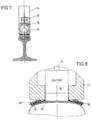
- Figure 7 is a section on a larger scale according to line A-A in Figure 1.
- Figure 8 is an enlarged detail of the figure 7.
- this device detection and / or ultrasonic measurement of faults of a railroad is to place between the probe (s) and the rail to examine a tape or belt to avoid direct contact between the rail and the probes.
- This strip can be made of synthetic material by polyamide example and have very smooth. This band is flexible so that it can fit the undulations of the rail.
- the strip is endless, closed on itself, passes between the probes and the rail then is wrapped around rollers and is subjected to the action of a tension roller.
- the part of the strip between the probes and the rail does not does not move relative to the rail, like a track, and the probes slide on the smooth surface of the bandaged.
- means are provided to ensure good sound contact between the probes and the tape as well between the strip and the rail, for example in the form of water films.
- the particular illustrated embodiment of the device for detecting and / or measuring internal faults of a rail using ultrasound includes a carrier trolley 1 running on the railway and intended to be connected to a rail vehicle (not shown), usually mounted under it, to be able to be dragged along the channel for detection or measurement.
- This carrier trolley 1 can also be connected to the chassis of the rail vehicle by lifting means to prevent this carriage does not roll on the track when walking high of the rail vehicle between two measurement sites or detection, for example.
- One or more of these carts carriers 1 can be placed under a railway vehicle, between its bogies, and each of these carrying carts 1 has flanged wheels 2 with the aid of which he rolls and is guided along the railway track.
- Each carrying trolley 1 carries at least one measure 3 for each line of rails in the track.
- These measuring carts 3 have a frame 4 connected by two cylinders 5 to the chassis of the carrying carriage 1 using which this measuring carriage 3 can either be lowered into position working low, or raised to the high rest position.
- the measuring carriage 3 has end rollers 6 crazy pivoted on the end of an arm 7 pivoted on the frame 4 and comprising a connecting rod 8 whose end is connected by a double-acting cylinder 9 to the frame 4.
- the cylinders 9 it is possible to modify the height of the corresponding roller 6 relative to the frame 4 of the measuring cart.
- Each of these rollers 6 ( Figures 5,6) has a part central with a groove receiving a bandage 10 in rubber for example intended to absorb transmitted shocks by the rail when this roller is resting on the rail.
- the lateral parts of the roller 6 are conical and can have teeth 11.
- the upper part of the frame 4 of the measuring carriage is fitted with a tensioner roller 12 that can be moved vertically relative to frame 4 for example using a jack (not shown).
- the periphery of this tensioner roller 12 is also toothed.
- the lower part of the frame 4 is connected using the double-acting cylinder 13 with measuring pads 14 having each two ultrasonic probes 15.
- Each measurement pad 14 (FIG. 2) carries two probes 15 sliding climbs along a vertical axis in the skid and subjected to the action of a single-acting cylinder 16 serving as shock absorber.
- This shoe 14 can be provided a water supply and recovery circuit to ensure the sound contact.
- this measuring carriage 3 is equipped with an endless belt 17 in smooth synthetic material such as polyacetane by example, and permeable to ultrasound, arranged below the surface lower of the probes and around the rollers 6.12.
- This endless band 17 is provided by gluing, welding or any other suitable means, in its two lateral parts, of toothed belts 18 incorporating cables or ropes 19 which prohibit any elongation of the strip.
- These belts notches 18 mesh with the teeth of the roller 12 and possibly rollers 6 and prevents any slipping of the strip 17 as well as its crossing.
- the notches of the belts 18 can be formed by lugs by example cooperating with corresponding roller bodies 12 and / or 6. Furthermore, these rollers may have smooth side parts.
- the carriage 3 is placed in the lower position, the strip 17 comes into contact with the rail.
- the measurement pads 14 are applied against the upper face of the strip 17 with a force determined by the cylinders 13 and the probes 15 are kept in contact with the surface of the smooth strip 17 by the damping cylinders 16.
- the strip 17 remains applied in contact with the rail and the measuring carriage 3 moving longitudinally there unrolls strip 17 like a caterpillar along the rail and the 15 probes slide on the smooth surface of the band 17 without rebounds, shocks or wear.
- the roller 6 located in the direction of travel is slightly lifted by its jack 9 and an injection device of water 20 creates a liquid film between the strip 17 and the rail to ensure good ultrasonic contact.
- the cart of measurement also includes injection means of water between the strip 17 and the measurement pads 14 for ensure good sound contact. These latter means may be deleted when the measurement pads 14 have an incorporated water injection system.
- rollers 6 it is possible to design the rollers 6 to be motorized by driving strip 17 which has the consequence of causing a displacement relative between the strip and the rail and decrease the speed of the relative movement between the probes and the bandaged. Such an arrangement can be advantageous for increase working speed while ensuring good ultrasonic contact between the probe and the rail through the band 17.
Landscapes
- Physics & Mathematics (AREA)
- Health & Medical Sciences (AREA)
- Life Sciences & Earth Sciences (AREA)
- Chemical & Material Sciences (AREA)
- Analytical Chemistry (AREA)
- Biochemistry (AREA)
- General Health & Medical Sciences (AREA)
- General Physics & Mathematics (AREA)
- Immunology (AREA)
- Pathology (AREA)
- Engineering & Computer Science (AREA)
- Mechanical Engineering (AREA)
- Investigating Or Analyzing Materials By The Use Of Ultrasonic Waves (AREA)
- Length Measuring Devices Characterised By Use Of Acoustic Means (AREA)
Claims (9)
- Vorrichtung zur kontinuierlichen in-situ-Ultraschall-Erfassung und/oder -Messung von internen Fehlern von zumindest einer Schiene eines Bahngleises mit zumindest einer Ultraschallsonde (15), die einem Druck ausgesetzt ist, der sie zur Schiene hin zu bewegen sucht, dadurch gekennzeichnet, dass die Sonde oder Sonden (15) über ein ultraschalldurchlässiges glattes Band (17) aus Kunststoff auf der Schiene aufliegen, und dadurch, dass Organe vorgesehen sind, um Flüssigfilme zwischen der Sonde oder den Sonden und dem Band sowie zwischen besagtem Band (17) und der Schienenoberfläche zu schaffen.
- Vorrichtung nach Anspruch 1, dadurch gekennzeichnet, dass sie mit Hilfe von Winden (5), die es gestatten, sie in eine Ruhe-Hochstellung oder eine Arbeits-Tiefstellung zu bringen, an einem Tragschlitten (1) montiert werden kann, wobei der benannte Tragschlitten (1) mit einem Eisenbahnfahrzeug verbunden ist.
- Vorrichtung nach Anspruch 1 oder Anspruch 2, dadurch gekennzeichnet, dass sie einen Messwagen (3) umfasst, der an jedem seiner Enden eine Endrolle (6) und auf seiner Oberseite eine Spannrolle (12) umfasst, dadurch, dass sie weiter einen mit Hilfe von Stützwinden (13) montierten Messschuh (14) mit zumindest einer Ultraschallsonde (15) umfasst, und dadurch, dass ein endloses Kunststoffband (17) zwischen den benannten Winden (6, 12) und den Messoberflächen der Sonden (15) eingespannt ist.
- Vorrichtung nach Anspruch 3, dadurch gekennzeichnet, dass die Endrollen (6) beweglich an einem Rahmen (4) des Messwagens (3) befestigt sind, um bezüglich der Schienenebene angehoben werden zu können.
- Vorrichtung nach Anspruch 3 oder Anspruch 4, dadurch gekennzeichnet, dass das endlose Band (17) gerippte Riemen (18) auf seinen seitlichen Partien umfasst.
- Vorrichtung nach Anspruch 5, dadurch gekennzeichnet, dass die seitlichen Partien der Endrollen (6) gezahnt und sind und dass sich diese seitlichen Partien nach aussen hin konisch verengen, und dadurch, dass der zentrale Abschnitt dieser Rollen mit einem elastischen Mantel (10) ausgerüstet ist.
- Vorrichtung nach Anspruch 6, dadurch gekennzeichnet, dass die gerippten Partien eingearbeitete Kabel oder Seile (19) umfassen.
- Vorrichtung nach Anspruch 5, dadurch gekennzeichnet, dass die Endrollen (6) frei laufen oder in Umdrehung versetzt werden.
- Vorrichtung nach Anspruch 5, dadurch gekennzeichnet, dass die Riemenkerben mit entsprechenden Organen an den Endrollen (6) und/oder an der Spannrolle (12) zusammenwirken.
Applications Claiming Priority (3)
| Application Number | Priority Date | Filing Date | Title |
|---|---|---|---|
| CH02898/96A CH690851A5 (fr) | 1996-11-25 | 1996-11-25 | Dispositif de mesure des défauts internes d'un rail par ultrasons. |
| CH289896 | 1996-11-25 | ||
| CH2898/96 | 1996-11-25 |
Publications (2)
| Publication Number | Publication Date |
|---|---|
| EP0844162A1 EP0844162A1 (de) | 1998-05-27 |
| EP0844162B1 true EP0844162B1 (de) | 2001-03-21 |
Family
ID=4244102
Family Applications (1)
| Application Number | Title | Priority Date | Filing Date |
|---|---|---|---|
| EP97107249A Expired - Lifetime EP0844162B1 (de) | 1996-11-25 | 1997-05-02 | Ultraschall- Messvorrichtung für interne Fehler einer Schiene |
Country Status (9)
| Country | Link |
|---|---|
| US (1) | US5804731A (de) |
| EP (1) | EP0844162B1 (de) |
| JP (1) | JP3768642B2 (de) |
| AT (1) | ATE199862T1 (de) |
| AU (1) | AU720996B2 (de) |
| CA (1) | CA2204173C (de) |
| CH (1) | CH690851A5 (de) |
| DE (1) | DE69704326T2 (de) |
| ZA (1) | ZA977595B (de) |
Cited By (1)
| Publication number | Priority date | Publication date | Assignee | Title |
|---|---|---|---|---|
| CN108819978A (zh) * | 2018-06-22 | 2018-11-16 | 辽宁工程技术大学 | 一种煤矿井下矿车轨道检测车 |
Families Citing this family (43)
| Publication number | Priority date | Publication date | Assignee | Title |
|---|---|---|---|---|
| US6424150B2 (en) * | 1999-03-17 | 2002-07-23 | Southwest Research Institute | Magnetostrictive sensor rail inspection system |
| ES2200533T3 (es) * | 1998-07-22 | 2004-03-01 | Fraunhofer-Gesellschaft Zur Forderung Der Angewandten Forschung E.V. | Dispositivo para la inspeccion ultrasonica. |
| US6516668B2 (en) * | 2000-01-05 | 2003-02-11 | Harsco Track Technologies, Inc. | Automatic carriage alignment |
| US10308265B2 (en) | 2006-03-20 | 2019-06-04 | Ge Global Sourcing Llc | Vehicle control system and method |
| US9733625B2 (en) | 2006-03-20 | 2017-08-15 | General Electric Company | Trip optimization system and method for a train |
| US9950722B2 (en) | 2003-01-06 | 2018-04-24 | General Electric Company | System and method for vehicle control |
| DE10334902B3 (de) * | 2003-07-29 | 2004-12-09 | Nutronik Gmbh | Verfahren und Schaltungsanordnung zur Verarbeitung von Signalen, die bei der zerstörungsfreien Prüfung von Gegenständen durch Reflexion von Ultraschallwellen erzeugt werden |
| RU2266225C1 (ru) * | 2004-04-13 | 2005-12-20 | Горделий Виталий Иванович | Мобильное устройство для контроля рельсового пути |
| US9956974B2 (en) | 2004-07-23 | 2018-05-01 | General Electric Company | Vehicle consist configuration control |
| US7305885B2 (en) * | 2004-09-30 | 2007-12-11 | General Electric Company | Method and apparatus for phased array based ultrasonic evaluation of rail |
| NL1028325C2 (nl) * | 2005-02-17 | 2006-08-21 | Sonimex B V | Werkwijze alsmede inrichting voor het detecteren van fouten in een railkop. |
| US9828010B2 (en) | 2006-03-20 | 2017-11-28 | General Electric Company | System, method and computer software code for determining a mission plan for a powered system using signal aspect information |
| GB2436363B (en) * | 2006-03-24 | 2009-06-03 | Sperry Rail | System and method for the detection of faults in rails |
| ITVE20070044A1 (it) * | 2007-07-06 | 2009-01-07 | Tecnogamma S P A | Metodo ed apparecchiatura per l'ispezione dinamica non a contatto delle rotaie ferroviarie. |
| GB0800406D0 (en) * | 2008-01-10 | 2008-02-20 | Sperry Rail International Ltd | Sensor assembly |
| US8914171B2 (en) | 2012-11-21 | 2014-12-16 | General Electric Company | Route examining system and method |
| EP2270489B1 (de) * | 2009-07-02 | 2018-09-05 | HITACHI RAIL ITALY S.p.A. | Verfahren und System zur Fehlererkennung |
| KR101196826B1 (ko) | 2010-11-18 | 2012-11-01 | 한국철도기술연구원 | 레일용 자동 초음파 탐지장치 |
| AU2013299501B2 (en) | 2012-08-10 | 2017-03-09 | Ge Global Sourcing Llc | Route examining system and method |
| AU2014272135B2 (en) | 2013-05-30 | 2020-01-16 | Wabtec Holding Corp. | Broken rail detection system for communications-based train control |
| JP6288953B2 (ja) * | 2013-06-03 | 2018-03-07 | 東京計器株式会社 | レール検査装置 |
| US9255913B2 (en) | 2013-07-31 | 2016-02-09 | General Electric Company | System and method for acoustically identifying damaged sections of a route |
| US9701326B2 (en) | 2014-09-12 | 2017-07-11 | Westinghouse Air Brake Technologies Corporation | Broken rail detection system for railway systems |
| US10349491B2 (en) | 2015-01-19 | 2019-07-09 | Tetra Tech, Inc. | Light emission power control apparatus and method |
| CA2892952C (en) | 2015-01-19 | 2019-10-15 | Tetra Tech, Inc. | Protective shroud |
| CA2893007C (en) | 2015-01-19 | 2020-04-28 | Tetra Tech, Inc. | Sensor synchronization apparatus and method |
| US10362293B2 (en) | 2015-02-20 | 2019-07-23 | Tetra Tech, Inc. | 3D track assessment system and method |
| WO2017168795A1 (ja) * | 2016-03-31 | 2017-10-05 | 株式会社Ihi | 非破壊検査方法及び接触媒質押付用治具 |
| CN106248804A (zh) * | 2016-09-26 | 2016-12-21 | 中车洛阳机车有限公司 | 一种钢轨超声波探伤轨道车辆的供水装置 |
| CN108163010B (zh) * | 2018-01-19 | 2019-06-04 | 西南交通大学 | 一种模块化钢轨探伤车 |
| US11377130B2 (en) | 2018-06-01 | 2022-07-05 | Tetra Tech, Inc. | Autonomous track assessment system |
| US10730538B2 (en) | 2018-06-01 | 2020-08-04 | Tetra Tech, Inc. | Apparatus and method for calculating plate cut and rail seat abrasion based on measurements only of rail head elevation and crosstie surface elevation |
| US10625760B2 (en) | 2018-06-01 | 2020-04-21 | Tetra Tech, Inc. | Apparatus and method for calculating wooden crosstie plate cut measurements and rail seat abrasion measurements based on rail head height |
| US10807623B2 (en) | 2018-06-01 | 2020-10-20 | Tetra Tech, Inc. | Apparatus and method for gathering data from sensors oriented at an oblique angle relative to a railway track |
| AU2019333159B2 (en) * | 2018-08-30 | 2022-07-28 | Voestalpine Signaling Usa Inc. | Railcar acoustic monitoring system and method of use |
| US12240505B2 (en) * | 2019-02-10 | 2025-03-04 | Scanmaster Systems (Irt) Ltd. | Low maintenance rail monitoring probe |
| WO2020232431A1 (en) | 2019-05-16 | 2020-11-19 | Tetra Tech, Inc. | System and method for generating and interpreting point clouds of a rail corridor along a survey path |
| US12275467B2 (en) | 2021-01-25 | 2025-04-15 | Caterpillar Inc. | Ultrasonic wear measurement for a track pad |
| CN113022606B (zh) * | 2021-03-25 | 2022-04-26 | 神华新朔铁路有限责任公司 | 钢轨探伤小车及钢轨探伤机车 |
| CN113022641B (zh) * | 2021-03-25 | 2022-04-29 | 神华新朔铁路有限责任公司 | 轨道探伤机构及轨道探伤车 |
| AT525016B1 (de) * | 2021-05-06 | 2025-10-15 | Mate Gmbh | Verfahren und Vorrichtung zum Ermitteln der Oberflächenbeschaffenheit an zumindest einem Schienenkopf |
| US12570336B2 (en) | 2022-07-19 | 2026-03-10 | Herzog Services, Inc. | System for detecting defects in rail and methods of using same |
| US12286142B2 (en) * | 2022-07-19 | 2025-04-29 | Herzog Services, Inc. | Utility body for housing system for detecting defects in rail |
Family Cites Families (14)
| Publication number | Priority date | Publication date | Assignee | Title |
|---|---|---|---|---|
| US3028751A (en) * | 1955-12-29 | 1962-04-10 | Ivan L Joy | Means for ultrasonic inspection of rail |
| US2992553A (en) * | 1957-04-24 | 1961-07-18 | Ivan L Joy | Coupling method and apparatus for ultrasonic testing of solid bodies |
| US3028753A (en) * | 1959-07-13 | 1962-04-10 | Ivan L Joy | Apparatus for wetting surfaces for ultrasonic testing |
| NL293655A (de) * | 1962-06-27 | |||
| US3768306A (en) * | 1971-12-20 | 1973-10-30 | C Stearns | Ultrasonic apparatus and method for analyzing defects in material |
| AU483896B2 (en) * | 1974-05-24 | 1975-11-27 | William Gieskieng Marion | Method and apparatus forthe detection of cracks and flaws in rail wheels, rails andthe like by sliding a prerecorded magnetic medium overthe test place |
| US3960005A (en) * | 1974-08-09 | 1976-06-01 | Canac Consultants Limited | Ultrasonic testing device for inspecting thermit rail welds |
| US4593569A (en) * | 1983-08-22 | 1986-06-10 | Joy Ivan L | Ultrasonic transducer unit to locate cracks in rail base |
| FR2561779B1 (fr) * | 1984-03-23 | 1987-08-28 | Sncf | Procede et dispositif de controle non destructif d'un rail de voie ferree |
| DE3424386A1 (de) * | 1984-07-03 | 1986-01-09 | Omnitest Gesellschaft für Qualitätssicherung mbH, 4690 Herne | Ankopplungs- und kopffuehrungsfolie fuer manuelle ultraschallpruefungen |
| CH665909A5 (fr) * | 1985-05-15 | 1988-06-15 | Matix Ind Sa | Procede et dispositif de detection par ultrasons des defauts internes d'un rail de chemin de fer situes dans les bords du champignon de ce rail, utilisation du dispositif. |
| CH677973A5 (de) * | 1988-12-19 | 1991-07-15 | Speno International | |
| US5419195A (en) * | 1993-04-30 | 1995-05-30 | Westinghouse Electric Corporation | Ultrasonic booted head probe for motor bore inspection |
| ATE166035T1 (de) * | 1994-04-06 | 1998-05-15 | Speno International | Ultraschall-messvorrichtung für fehler einer eisenbahnschiene |
-
1996
- 1996-11-25 CH CH02898/96A patent/CH690851A5/fr not_active IP Right Cessation
-
1997
- 1997-04-23 US US08/839,179 patent/US5804731A/en not_active Expired - Lifetime
- 1997-04-30 CA CA002204173A patent/CA2204173C/fr not_active Expired - Lifetime
- 1997-05-02 DE DE69704326T patent/DE69704326T2/de not_active Expired - Lifetime
- 1997-05-02 AT AT97107249T patent/ATE199862T1/de active
- 1997-05-02 EP EP97107249A patent/EP0844162B1/de not_active Expired - Lifetime
- 1997-05-20 JP JP12984497A patent/JP3768642B2/ja not_active Expired - Lifetime
- 1997-05-21 AU AU23555/97A patent/AU720996B2/en not_active Expired
- 1997-08-25 ZA ZA9707595A patent/ZA977595B/xx unknown
Cited By (1)
| Publication number | Priority date | Publication date | Assignee | Title |
|---|---|---|---|---|
| CN108819978A (zh) * | 2018-06-22 | 2018-11-16 | 辽宁工程技术大学 | 一种煤矿井下矿车轨道检测车 |
Also Published As
| Publication number | Publication date |
|---|---|
| CA2204173A1 (fr) | 1998-05-25 |
| HK1010175A1 (en) | 1999-06-17 |
| DE69704326D1 (de) | 2001-04-26 |
| CH690851A5 (fr) | 2001-02-15 |
| EP0844162A1 (de) | 1998-05-27 |
| CA2204173C (fr) | 2006-06-13 |
| AU720996B2 (en) | 2000-06-22 |
| ZA977595B (en) | 1998-05-25 |
| US5804731A (en) | 1998-09-08 |
| AU2355597A (en) | 1998-05-28 |
| JPH10160713A (ja) | 1998-06-19 |
| JP3768642B2 (ja) | 2006-04-19 |
| DE69704326T2 (de) | 2001-08-23 |
| ATE199862T1 (de) | 2001-04-15 |
Similar Documents
| Publication | Publication Date | Title |
|---|---|---|
| CA2204173C (fr) | Dispositif de mesure des defauts internes d'un rail par ultrasons | |
| EP0019984B1 (de) | Zug zum Erneuern eines Eisenbahngleises | |
| CA2960074C (fr) | Funiculaire entraine par un cable en boucle fermee a deux troncons tracteurs et procede de commande d'un tel funiculaire | |
| EP0114284B1 (de) | Vorrichtung zum kontinuierlichen Messen der Form des Querprofils des Nutzteiles des Kopfes von mindestens einer Eisenbahnschiene | |
| FR2476708A1 (fr) | Ensemble mobile pour le nettoyage de la couche de ballast des voies ferrees et procede de nettoyage utilisant un tel ensemble | |
| FR3050985A1 (fr) | Convoyeur a bande avec dispositif d'evaluation de la tension de la bande | |
| CA2064966C (fr) | Crepeuse | |
| FR2672238A1 (fr) | Rectification des pneumatiques. | |
| EP0849397A1 (de) | Vorrichtung zum kontinuierlichen Endbearbeiten der Reprofilierung des Kopfes einer Eisenbahnschiene | |
| FR2579962A1 (de) | ||
| EP0208598B1 (de) | Schienengeführtes Fahrzeug mit Schwenkbaren Radachsen | |
| EP2905195B1 (de) | Mobile messvorrichtung für ein schienenkopfprofil | |
| FR2636041A1 (fr) | Appareil pour emballer des produits en vrac | |
| EP0332489B1 (de) | Stellvorrichtung für ein Eisenbahnfahrzeug auf einer Raddrehbank | |
| CA2484766C (fr) | Roue de vehicule ferroviaire, et bogie de vehicule ferroviaire correspondant | |
| EP0968905A1 (de) | Einer Tunnelvortriebsmaschine folgender Güterwagenzug | |
| FR2517718A1 (fr) | Dispositif pour le tracage de pistes de ski | |
| FR2657901A1 (fr) | Machine de bourrage de voie ferree. | |
| FR3001447A1 (fr) | Convoyeur a bande et ensemble comportant un tel convoyeur | |
| CA1024824A (en) | Continuous variable speed control system for travelling railings | |
| HK1010175B (en) | Ultrasonic measuring device of internal faults of a rail | |
| FR2809069A1 (fr) | Vehicule ferroviaire comportant une voiture d'extremite se prolongeant par une cabine | |
| EP0015790A1 (de) | Endloser Senkrechtförderer | |
| FR2766217A1 (fr) | Machine a bande abrasive pour elimination de l'usure ondulatoire d'un rail de chemin de fer | |
| FR2490171A1 (fr) | Bogie muni d'une poutre transversale pour l'appui de la caisse d'un vehicule ferroviaire |
Legal Events
| Date | Code | Title | Description |
|---|---|---|---|
| PUAI | Public reference made under article 153(3) epc to a published international application that has entered the european phase |
Free format text: ORIGINAL CODE: 0009012 |
|
| AK | Designated contracting states |
Kind code of ref document: A1 Designated state(s): AT BE CH DE FR GB IT LI NL SE |
|
| AX | Request for extension of the european patent |
Free format text: AL;LT;LV;RO;SI |
|
| 17P | Request for examination filed |
Effective date: 19980925 |
|
| AKX | Designation fees paid |
Free format text: AT BE CH DE FR GB IT LI NL SE |
|
| RBV | Designated contracting states (corrected) |
Designated state(s): AT BE CH DE FR GB IT LI NL SE |
|
| GRAG | Despatch of communication of intention to grant |
Free format text: ORIGINAL CODE: EPIDOS AGRA |
|
| GRAG | Despatch of communication of intention to grant |
Free format text: ORIGINAL CODE: EPIDOS AGRA |
|
| GRAH | Despatch of communication of intention to grant a patent |
Free format text: ORIGINAL CODE: EPIDOS IGRA |
|
| 17Q | First examination report despatched |
Effective date: 20000731 |
|
| RAP1 | Party data changed (applicant data changed or rights of an application transferred) |
Owner name: SPENO INTERNATIONAL SA |
|
| GRAH | Despatch of communication of intention to grant a patent |
Free format text: ORIGINAL CODE: EPIDOS IGRA |
|
| GRAA | (expected) grant |
Free format text: ORIGINAL CODE: 0009210 |
|
| AK | Designated contracting states |
Kind code of ref document: B1 Designated state(s): AT BE CH DE FR GB IT LI NL SE |
|
| REF | Corresponds to: |
Ref document number: 199862 Country of ref document: AT Date of ref document: 20010415 Kind code of ref document: T |
|
| ITF | It: translation for a ep patent filed | ||
| REG | Reference to a national code |
Ref country code: CH Ref legal event code: NV Representative=s name: MICHELI & CIE INGENIEURS-CONSEILS Ref country code: CH Ref legal event code: EP |
|
| REF | Corresponds to: |
Ref document number: 69704326 Country of ref document: DE Date of ref document: 20010426 |
|
| GBT | Gb: translation of ep patent filed (gb section 77(6)(a)/1977) |
Effective date: 20010405 |
|
| REG | Reference to a national code |
Ref country code: GB Ref legal event code: IF02 |
|
| PLBE | No opposition filed within time limit |
Free format text: ORIGINAL CODE: 0009261 |
|
| STAA | Information on the status of an ep patent application or granted ep patent |
Free format text: STATUS: NO OPPOSITION FILED WITHIN TIME LIMIT |
|
| 26N | No opposition filed | ||
| REG | Reference to a national code |
Ref country code: FR Ref legal event code: PLFP Year of fee payment: 20 |
|
| PGFP | Annual fee paid to national office [announced via postgrant information from national office to epo] |
Ref country code: NL Payment date: 20160519 Year of fee payment: 20 |
|
| PGFP | Annual fee paid to national office [announced via postgrant information from national office to epo] |
Ref country code: CH Payment date: 20160413 Year of fee payment: 20 Ref country code: DE Payment date: 20160520 Year of fee payment: 20 Ref country code: GB Payment date: 20160520 Year of fee payment: 20 |
|
| PGFP | Annual fee paid to national office [announced via postgrant information from national office to epo] |
Ref country code: IT Payment date: 20160524 Year of fee payment: 20 Ref country code: FR Payment date: 20160520 Year of fee payment: 20 Ref country code: SE Payment date: 20160519 Year of fee payment: 20 Ref country code: BE Payment date: 20160519 Year of fee payment: 20 Ref country code: AT Payment date: 20160520 Year of fee payment: 20 |
|
| REG | Reference to a national code |
Ref country code: DE Ref legal event code: R071 Ref document number: 69704326 Country of ref document: DE |
|
| REG | Reference to a national code |
Ref country code: NL Ref legal event code: MK Effective date: 20170501 |
|
| REG | Reference to a national code |
Ref country code: CH Ref legal event code: PL |
|
| REG | Reference to a national code |
Ref country code: GB Ref legal event code: PE20 Expiry date: 20170501 |
|
| REG | Reference to a national code |
Ref country code: AT Ref legal event code: MK07 Ref document number: 199862 Country of ref document: AT Kind code of ref document: T Effective date: 20170502 |
|
| REG | Reference to a national code |
Ref country code: SE Ref legal event code: EUG |
|
| PG25 | Lapsed in a contracting state [announced via postgrant information from national office to epo] |
Ref country code: GB Free format text: LAPSE BECAUSE OF EXPIRATION OF PROTECTION Effective date: 20170501 |