EP0332705A1 - Einrichtung zur eingangssignalhöhenbestimmung - Google Patents
Einrichtung zur eingangssignalhöhenbestimmung Download PDFInfo
- Publication number
- EP0332705A1 EP0332705A1 EP88906896A EP88906896A EP0332705A1 EP 0332705 A1 EP0332705 A1 EP 0332705A1 EP 88906896 A EP88906896 A EP 88906896A EP 88906896 A EP88906896 A EP 88906896A EP 0332705 A1 EP0332705 A1 EP 0332705A1
- Authority
- EP
- European Patent Office
- Prior art keywords
- input signal
- threshold level
- signal
- time
- input
- Prior art date
- Legal status (The legal status is an assumption and is not a legal conclusion. Google has not performed a legal analysis and makes no representation as to the accuracy of the status listed.)
- Withdrawn
Links
- 238000012850 discrimination method Methods 0.000 claims abstract description 8
- 230000002035 prolonged effect Effects 0.000 description 4
- 238000010586 diagram Methods 0.000 description 3
- 239000003990 capacitor Substances 0.000 description 2
- 238000010276 construction Methods 0.000 description 2
- 238000001514 detection method Methods 0.000 description 1
- 238000009499 grossing Methods 0.000 description 1
Images


Classifications
-
- G—PHYSICS
- G01—MEASURING; TESTING
- G01R—MEASURING ELECTRIC VARIABLES; MEASURING MAGNETIC VARIABLES
- G01R19/00—Arrangements for measuring currents or voltages or for indicating presence or sign thereof
- G01R19/145—Indicating the presence of current or voltage
-
- G—PHYSICS
- G01—MEASURING; TESTING
- G01R—MEASURING ELECTRIC VARIABLES; MEASURING MAGNETIC VARIABLES
- G01R29/00—Arrangements for measuring or indicating electric quantities not covered by groups G01R19/00 - G01R27/00
- G01R29/02—Measuring characteristics of individual pulses, e.g. deviation from pulse flatness, rise time or duration
- G01R29/027—Indicating that a pulse characteristic is either above or below a predetermined value or within or beyond a predetermined range of values
- G01R29/0273—Indicating that a pulse characteristic is either above or below a predetermined value or within or beyond a predetermined range of values the pulse characteristic being duration, i.e. width (indicating that frequency of pulses is above or below a certain limit)
Definitions
- the present invention relates to an input signal discrimination method for discriminating an AC input signal by a PLC (programmable logic controller) or the like, and more particularly to an input signal discrimination method for discriminating the state of an AC input signal by counting pulses.
- PLC programmable logic controller
- Figure 4 shows an input circuit conventionally used to discriminate an AC input signal by a PLC or the like.
- 1 represents an AC input signal
- 10 represents an input circuit
- 20 represents a PLC for processing the input signal.
- the input circuit 10 includes a rectifier circuit 11 for carrying out a full-wave rectification of the input signal, a resistor R and a capacitor C for smoothing the signal, and a photocoupler 12 to which the smoothed signal is supplied, to thereby separate a DC output from the AC input signal 1.
- a resistor R1 in cooperation with the resistor R, divides the voltage of the AC input signal 1 to lower the output level.
- the PLC discriminates the state, and carries out a sequence processing, of the AC input signal 1, based on the signal from the photocoupler 12.
- the output of the input circuit 10 must be a ripple-free signal, and therefore, the time constant R1 ⁇ C of the circuit must be large. As a result, the response time of the input circuit 10 is prolonged and it is difficult to obtain a value shorter than three cycles of the alternating current of the AC input signal.
- the object of the present invention is to provide an input signal discrimination method which solves the above-mentioned problem and in which the state of an AC input signal is discriminated by counting pulses.
- the present invention provides an input signal discrimination method of discriminating an AC input signal, comprising: carrying out a pulse count in a time for which the AC input signal remains above a predetermined threshold level and a time for which the AC input signal remains below the predetermined threshold level; deciding that the AC input signal is on when the number of pulses counted while the AC input signal remains above the predetermined threshold level is larger than a previously calculated number of pulses; and deciding that the AC input signal is off when the number of pulses counted while the AC input signal remains below the predetermined threshold level is larger than a previously calculated number of pulses.
- the signal level remains higher than the threshold level for a predetermined time, and therefore, this high-level time is discriminated by the number of pulses counted to discriminate the signal on state.
- the signal level remains lower than the threshold level for a predetermined time, and therefore, this low-level time is discriminated by the number of pulses counted to discriminate the signal off state.
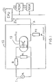
- FIG. 1 is a block diagram illustrating an embodiment of the present invention.
- 1 denotes an AC input signal, the on or off state of which is determined by the effective value thereof
- 10 represents an input circuit which receives the AC input signal 1 and outputs a DC signal.
- the input circuit 10 includes resistors R and R1 which carry out a voltage division of the input signal and apply the divided voltage to a photocoupler 13.
- the photocoupler 13 includes light-emitting diodes connected in an inverse-parallel fashion as shown in the figure, for turning on a transistor when a current having a level higher than the threshold level flows in either direction.
- Vcc designates a voltage applied to a logic circuit and is usually +5 V
- R2 denotes a voltage detection resistor.
- the input circuit outputs, from an output terminal A thereof, a signal obtained by carrying out a full-wave rectification of the AC input signal 1.
- Numeral 21 denotes a processor of a PLC (programmable logic controller) for global control of the PLC
- 22 denotes a ROM for storing a monitor program for the PLC, a sequence program, and the like
- 23 denotes a RAM for storing various data and a signal output from the input circuit 10 through the processor 21.
- PLC programmable logic controller
- the output of the input circuit 10, which is connected to an input port of the processor 21, is read by the processor 21 in a cycle shorter than one cycle of the AC input signal 1.
- the processor 21 When the AC input signal 1 is on, the output level of the input circuit 10 remains higher than the threshold level for longer than a predetermined time, and accordingly, the signal on time is prolonged.
- the AC input signal is off, the time for which the output level remains below the threshold level is prolonged, and therefore, this time is counted by the processor to discriminate the state of the AC input signal.
- FIG. 2 is a timing chart illustrating the embodiment of the invention.
- C1 represents the AC input signal 1 in FIG. 1
- C2 represents the voltage across the resistor R1 the ratio of magnitude between the two is actually about 20:1 although the ratio illustrated is about 2:1.
- Straight lines L1 and L2 indicate the threshold levels of the photocoupler 13
- OUTPUT OF INPUT CIRCUIT indicates the output waveform at terminal A of the input circuit 10 in FIG. 1
- READ CYCLE represents the timing at which the processor 21 reads the output signal of the input circuit 10.
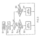
- the processor 21 decides that the input signal is on.
- the processor 21 decides that the input signal is off.
- the processor decides that the AC input signal 1 is on.
- the processor decides that the AC input signal 1 is on.
- the input signal remains off for longer than a time (n-N+1), then it is determined that the AC input signal is off.
- the processor 21 can discriminate the state of the AC input signal within the time (Th+tx), and of the resistor R, thus forming a similar circuitry.
- the signal from the input circuit may be connected to the input port of the processor through a bus.
- Such a construction is particularly practical when the number of input signals is large, because the number of input ports is relatively small.
- the construction of the present invention is such that the state of the AC input signal is discriminated by counting pulses, and accordingly, the response time is shortened and components such as a capacitor or the like can be omitted.
Landscapes
- Physics & Mathematics (AREA)
- General Physics & Mathematics (AREA)
- Electronic Switches (AREA)
- Measurement Of Current Or Voltage (AREA)
Applications Claiming Priority (2)
| Application Number | Priority Date | Filing Date | Title |
|---|---|---|---|
| JP206105/87 | 1987-08-19 | ||
| JP62206105A JPH07104376B2 (ja) | 1987-08-19 | 1987-08-19 | 交流入力信号判別装置 |
Publications (2)
| Publication Number | Publication Date |
|---|---|
| EP0332705A1 true EP0332705A1 (de) | 1989-09-20 |
| EP0332705A4 EP0332705A4 (de) | 1989-10-27 |
Family
ID=16517883
Family Applications (1)
| Application Number | Title | Priority Date | Filing Date |
|---|---|---|---|
| EP19880906896 Withdrawn EP0332705A4 (de) | 1987-08-19 | 1988-08-10 | Einrichtung zur eingangssignalhöhenbestimmung. |
Country Status (4)
| Country | Link |
|---|---|
| US (1) | US5019995A (de) |
| EP (1) | EP0332705A4 (de) |
| JP (1) | JPH07104376B2 (de) |
| WO (1) | WO1989001633A1 (de) |
Cited By (4)
| Publication number | Priority date | Publication date | Assignee | Title |
|---|---|---|---|---|
| US5190047A (en) * | 1989-07-25 | 1993-03-02 | Seiko Instruments Inc. | Photoelectric pulsation type pulsimeter |
| DE4220778A1 (de) * | 1992-06-25 | 1994-01-05 | Licentia Gmbh | Anordnung zur potentialfreien Überwachung von auf Leitungen übertragenen Wechselspannungen und zur Erzeugung eines binären Signals bei Überschreiten einer vorgebbaren Spannungsschwelle |
| WO2002010775A3 (en) * | 2000-08-02 | 2002-04-25 | Univ Johns Hopkins | EVENT COUNTING APPARATUS |
| WO2005029101A3 (en) * | 2003-09-17 | 2005-06-16 | Rockwell Automation Tech Inc | Method and system for verifying voltage in an electrical system |
Families Citing this family (12)
| Publication number | Priority date | Publication date | Assignee | Title |
|---|---|---|---|---|
| US4945760A (en) * | 1989-10-18 | 1990-08-07 | Hornung Thomas F | Combined motor tester and pulse train monitor for stepper motors |
| US5491722A (en) * | 1992-12-21 | 1996-02-13 | Communications Technology Corporation | Eye pattern margin measurement and receiver stress detection device |
| US5469364A (en) * | 1993-03-15 | 1995-11-21 | Hughey; Bradley W. | Apparatus and methods for measuring and detecting variations in the value of a capacitor |
| CN100567997C (zh) * | 2004-05-18 | 2009-12-09 | 汤姆森许可贸易公司 | 功率干扰检测电路及方法 |
| JP2006086663A (ja) * | 2004-09-15 | 2006-03-30 | Meidensha Corp | データ処理方法 |
| JP2006166506A (ja) * | 2004-12-03 | 2006-06-22 | Fuji Electric Systems Co Ltd | 電力変換装置の制御装置および電力変換装置 |
| CN101620258B (zh) * | 2009-04-20 | 2011-04-06 | 广东大榕树信息科技有限公司 | 电压闪停检测电路 |
| US8674681B2 (en) * | 2010-05-25 | 2014-03-18 | Rockwell Automation Technologies, Inc. | Voltage detection and measurement circuit |
| JP5924199B2 (ja) * | 2012-09-05 | 2016-05-25 | ソニー株式会社 | 電源監視装置、交直変換装置、および、電源監視装置の制御方法 |
| US9722608B2 (en) * | 2015-07-22 | 2017-08-01 | Mercury Systems Inc. | Multi-voltage to isolated logic level trigger |
| JP7672646B2 (ja) * | 2020-09-30 | 2025-05-08 | 株式会社システム設計 | 交流電源の瞬断又は/及び瞬低検知装置 |
| JP2024019024A (ja) * | 2022-07-29 | 2024-02-08 | 株式会社Gsec | フォトリレーを使った論理回路の構成方法、フォトリレーを使った論理回路、論理回路のシミュレータ及びプログラム |
Family Cites Families (14)
| Publication number | Priority date | Publication date | Assignee | Title |
|---|---|---|---|---|
| JPS5623172B2 (de) * | 1973-10-05 | 1981-05-29 | ||
| JPS5528512B2 (de) * | 1974-03-07 | 1980-07-28 | ||
| JPS5430308B2 (de) * | 1974-03-27 | 1979-09-29 | ||
| US4054834A (en) * | 1976-01-14 | 1977-10-18 | Compagnie Generale D'electricite S.A. | Device for measuring AC in a high tension line |
| JPS533636A (en) * | 1976-07-01 | 1978-01-13 | Takeda Riken Ind Co Ltd | Aac power service interruption detector |
| US4063121A (en) * | 1976-07-22 | 1977-12-13 | Automation Systems Inc. | Input converter |
| JPS5825233B2 (ja) * | 1977-12-16 | 1983-05-26 | 三菱電機株式会社 | レベル検出装置 |
| US4208627A (en) * | 1978-10-23 | 1980-06-17 | Bell Telephone Laboratories, Incorporated | Alarm circuit to detect shorting of periodic signal source |
| GB2078979B (en) * | 1980-06-23 | 1984-08-15 | Solartron Electronic Group | Methods and apparatus for assessing the quality of logic signals |
| JPS5852571A (ja) * | 1981-09-24 | 1983-03-28 | Fujitsu Ltd | キャリア検出回路 |
| US4475086A (en) * | 1982-03-31 | 1984-10-02 | Eastman Kodak Company | Duty cycle detector |
| JPS59214775A (ja) * | 1983-05-20 | 1984-12-04 | Mitsubishi Electric Corp | 交流電源の瞬断・瞬停検知装置 |
| JPS60100058A (ja) * | 1983-11-07 | 1985-06-03 | Fuji Electric Corp Res & Dev Ltd | 寿電検知回路 |
| JPH0562735A (ja) * | 1991-09-02 | 1993-03-12 | Mitsubishi Electric Corp | 集合ケーブルの接続構造 |
-
1987
- 1987-08-19 JP JP62206105A patent/JPH07104376B2/ja not_active Expired - Lifetime
-
1988
- 1988-08-10 WO PCT/JP1988/000791 patent/WO1989001633A1/ja not_active Ceased
- 1988-08-10 EP EP19880906896 patent/EP0332705A4/de not_active Withdrawn
- 1988-08-10 US US07/332,456 patent/US5019995A/en not_active Expired - Fee Related
Cited By (5)
| Publication number | Priority date | Publication date | Assignee | Title |
|---|---|---|---|---|
| US5190047A (en) * | 1989-07-25 | 1993-03-02 | Seiko Instruments Inc. | Photoelectric pulsation type pulsimeter |
| DE4220778A1 (de) * | 1992-06-25 | 1994-01-05 | Licentia Gmbh | Anordnung zur potentialfreien Überwachung von auf Leitungen übertragenen Wechselspannungen und zur Erzeugung eines binären Signals bei Überschreiten einer vorgebbaren Spannungsschwelle |
| WO2002010775A3 (en) * | 2000-08-02 | 2002-04-25 | Univ Johns Hopkins | EVENT COUNTING APPARATUS |
| WO2005029101A3 (en) * | 2003-09-17 | 2005-06-16 | Rockwell Automation Tech Inc | Method and system for verifying voltage in an electrical system |
| US7003412B2 (en) | 2003-09-17 | 2006-02-21 | Rockwell Automation Technologies, Inc. | Method and system for verifying voltage in an electrical system |
Also Published As
| Publication number | Publication date |
|---|---|
| JPH07104376B2 (ja) | 1995-11-13 |
| US5019995A (en) | 1991-05-28 |
| WO1989001633A1 (fr) | 1989-02-23 |
| EP0332705A4 (de) | 1989-10-27 |
| JPS6449978A (en) | 1989-02-27 |
Similar Documents
| Publication | Publication Date | Title |
|---|---|---|
| US5019995A (en) | Input signal discrimination method | |
| EP0377257A1 (de) | Identifizierungssystem | |
| EP0400389A2 (de) | Erfassung des Einschaltens einer Spule | |
| EP0158512A2 (de) | Rücksetzschaltung | |
| EP1986103A2 (de) | USB-Vorrichtung und Verfahren zur Steuerung der USB-Vorrichtung | |
| US20030067795A1 (en) | Synchronous rectification for low voltage motor drive | |
| JPS637900Y2 (de) | ||
| GB2339982A (en) | Crankshaft angle signal thresholder with asymmetric hysteresis | |
| US4763025A (en) | Frequency discrimination circuit | |
| JPH05297992A (ja) | プログラマブルコントローラの入力回路 | |
| JP2793226B2 (ja) | セルフ電源カウンタの入力判定方法 | |
| US5869996A (en) | Semiconductor composite element, and method of detecting abnormal conditions in an inverter device having the element | |
| JPS6329267A (ja) | パルス存在検出回路 | |
| JP2653189B2 (ja) | 電源周波数検出装置 | |
| JPH10162095A (ja) | スライスレシオ制御回路 | |
| EP0186740A1 (de) | Netzfrequenzdetektorsystem | |
| SU1242842A1 (ru) | Устройство дл контрол переменного напр жени | |
| EP0112948A1 (de) | Netzfrequenzdetektorsystem | |
| JPH0418792B2 (de) | ||
| JPH0321139A (ja) | 信号処理装置 | |
| SU1112262A1 (ru) | Устройство дл контрол износа инструмента на металлорежущих станках | |
| JPS5995700A (ja) | 誘導信号発信器の信号処理装置 | |
| SU1667171A1 (ru) | Устройство дл определени параметров переходного процесса | |
| KR0132839B1 (ko) | 직류 전압 검출기에 의한 디지털 전원 보호장치 | |
| JPH0119669B2 (de) |
Legal Events
| Date | Code | Title | Description |
|---|---|---|---|
| PUAI | Public reference made under article 153(3) epc to a published international application that has entered the european phase |
Free format text: ORIGINAL CODE: 0009012 |
|
| AK | Designated contracting states |
Kind code of ref document: A1 Designated state(s): DE FR GB |
|
| A4 | Supplementary search report drawn up and despatched |
Effective date: 19891027 |
|
| 17P | Request for examination filed |
Effective date: 19890511 |
|
| 17Q | First examination report despatched |
Effective date: 19911218 |
|
| STAA | Information on the status of an ep patent application or granted ep patent |
Free format text: STATUS: THE APPLICATION HAS BEEN WITHDRAWN |
|
| 18W | Application withdrawn |
Withdrawal date: 19920806 |