EP0332936A1 - Appareil de commutation accouplable - Google Patents
Appareil de commutation accouplable Download PDFInfo
- Publication number
- EP0332936A1 EP0332936A1 EP89103582A EP89103582A EP0332936A1 EP 0332936 A1 EP0332936 A1 EP 0332936A1 EP 89103582 A EP89103582 A EP 89103582A EP 89103582 A EP89103582 A EP 89103582A EP 0332936 A1 EP0332936 A1 EP 0332936A1
- Authority
- EP
- European Patent Office
- Prior art keywords
- coupling element
- switching
- claw
- shaped coupling
- shaped
- Prior art date
- Legal status (The legal status is an assumption and is not a legal conclusion. Google has not performed a legal analysis and makes no representation as to the accuracy of the status listed.)
- Granted
Links
- 230000008878 coupling Effects 0.000 title claims abstract description 48
- 238000010168 coupling process Methods 0.000 title claims abstract description 48
- 238000005859 coupling reaction Methods 0.000 title claims abstract description 48
- 210000000078 claw Anatomy 0.000 claims description 6
- 230000035515 penetration Effects 0.000 claims description 3
- 230000011664 signaling Effects 0.000 claims 1
- 230000005405 multipole Effects 0.000 description 2
- 230000001960 triggered effect Effects 0.000 description 1
Images
Classifications
-
- H—ELECTRICITY
- H01—ELECTRIC ELEMENTS
- H01H—ELECTRIC SWITCHES; RELAYS; SELECTORS; EMERGENCY PROTECTIVE DEVICES
- H01H71/00—Details of the protective switches or relays covered by groups H01H73/00 - H01H83/00
- H01H71/10—Operating or release mechanisms
- H01H71/12—Automatic release mechanisms with or without manual release
- H01H71/46—Automatic release mechanisms with or without manual release having means for operating auxiliary contacts additional to the main contacts
- H01H71/462—Automatic release mechanisms with or without manual release having means for operating auxiliary contacts additional to the main contacts housed in a separate casing, juxtaposed to and having the same general contour as the main casing
-
- H—ELECTRICITY
- H01—ELECTRIC ELEMENTS
- H01H—ELECTRIC SWITCHES; RELAYS; SELECTORS; EMERGENCY PROTECTIVE DEVICES
- H01H71/00—Details of the protective switches or relays covered by groups H01H73/00 - H01H83/00
- H01H71/10—Operating or release mechanisms
- H01H71/1009—Interconnected mechanisms
- H01H71/1018—Interconnected mechanisms with only external interconnections
-
- Y—GENERAL TAGGING OF NEW TECHNOLOGICAL DEVELOPMENTS; GENERAL TAGGING OF CROSS-SECTIONAL TECHNOLOGIES SPANNING OVER SEVERAL SECTIONS OF THE IPC; TECHNICAL SUBJECTS COVERED BY FORMER USPC CROSS-REFERENCE ART COLLECTIONS [XRACs] AND DIGESTS
- Y10—TECHNICAL SUBJECTS COVERED BY FORMER USPC
- Y10S—TECHNICAL SUBJECTS COVERED BY FORMER USPC CROSS-REFERENCE ART COLLECTIONS [XRACs] AND DIGESTS
- Y10S200/00—Electricity: circuit makers and breakers
- Y10S200/06—Tie bar
Definitions
- the invention relates to a switching device in a system of switching devices that can be coupled with switching or auxiliary switching or signal switching devices to be installed.
- Such switching devices are on the market in the most varied of embodiments.
- a multi-pole switch is constructed from single-pole circuit breakers in that the actuating handles are connected to one another by a rail-like bridge.
- the handles In order to be able to compensate for tolerances when assembling, the handles have central recesses on their end faces, into which knobs engage with play in the longitudinal direction of the bridge. Sometimes one would like to avoid such specially adapted bridge elements, which have to be carried along for the assembly.
- the invention has for its object to develop a system of switching devices that are to be coupled without coupling elements to be provided.
- a coupling element made from a pair of the function of claw-shaped coupling element and peg-shaped coupling element is implemented on the roller body in the direction of the switching axis on a receiving side .
- the coupling element which is movable behind a housing slot, the other coupling element of the functional pair can be brought into engagement, which is arranged in a housing slot on an outside of a device to be attached.
- a claw-shaped coupling element for example, can be arranged on the roller body in the direction of the switching axis on a receiving side, with which a peg-shaped coupling element cooperates in a housing slot on the outside, which engages the claw-shaped coupling element on the receiving side of the receiving device from a device to be attached.
- the claw-shaped coupling element is designed to have a claw tooth or a claw flank of the claw-shaped coupling element in the engagement depth only for a driver direction when the depth of penetration of a pin-shaped coupling element is less.
- the switchgear to be installed remains unaffected when switched off by hand.
- conditions can easily be met, such as are required between signal switches and circuit breakers of the type of the error signal switch.
- Such a signal switch should only be switched on via the switching handle of the circuit breaker but no longer be able to be switched off.
- the signal switch can only emit a signal if the circuit breaker has triggered in self-triggering.
- a separate tripping coupling ensures that the signal switch is only switched off as intended in the event of an overload, be it overcurrent or a short circuit on the miniature circuit breaker.
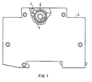
- the switching device 1 according to FIG. 1 has a roller-shaped manual control element 2, the switching handle 3 of which protrudes beyond the housing.
- a claw-shaped coupling element 4 is arranged on the roller body in the direction of the switching axis on a receiving side behind the plane of the drawing. This is movable behind a housing slot 5 with its receptacle.
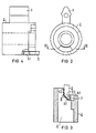
- a peg-shaped coupling element 6 according to FIG. 3 is arranged in a housing slot on an outside. The peg-shaped coupling element engages deeply in the claw-shaped coupling element 4.
- the pin-shaped coupling element 6 engages between the dog teeth 7 and 8 in the version 8.1.
- the peg-shaped coupling element 6 is only available in a short version 6.2, it is single in this engagement depth Lich the flank of a single claw tooth 8.2, but no claw tooth on its other side.
- a coupling is achieved for a long peg-shaped coupling element 6.1, as is desired for auxiliary switches, and a coupling as is desired for signal switches for a short peg-shaped coupling element 6.2. 1, both auxiliary switches and signal switches can be attached to the manual circuit breaker without additional coupling elements.
Landscapes
- Driving Mechanisms And Operating Circuits Of Arc-Extinguishing High-Tension Switches (AREA)
- Excavating Of Shafts Or Tunnels (AREA)
- Investigating Or Analyzing Materials By The Use Of Ultrasonic Waves (AREA)
- Transmitters (AREA)
- Structure Of Receivers (AREA)
- Details Of Connecting Devices For Male And Female Coupling (AREA)
- Magnetic Resonance Imaging Apparatus (AREA)
- Switches With Compound Operations (AREA)
- Massaging Devices (AREA)
- Friction Gearing (AREA)
- Breakers (AREA)
Applications Claiming Priority (2)
| Application Number | Priority Date | Filing Date | Title |
|---|---|---|---|
| DE3808472 | 1988-03-14 | ||
| DE3808472 | 1988-03-14 |
Publications (2)
| Publication Number | Publication Date |
|---|---|
| EP0332936A1 true EP0332936A1 (fr) | 1989-09-20 |
| EP0332936B1 EP0332936B1 (fr) | 1994-06-01 |
Family
ID=6349695
Family Applications (1)
| Application Number | Title | Priority Date | Filing Date |
|---|---|---|---|
| EP89103582A Expired - Lifetime EP0332936B1 (fr) | 1988-03-14 | 1989-03-01 | Appareil de commutation accouplable |
Country Status (8)
| Country | Link |
|---|---|
| US (1) | US4954671A (fr) |
| EP (1) | EP0332936B1 (fr) |
| AT (1) | ATE106603T1 (fr) |
| AU (1) | AU616738B2 (fr) |
| BR (1) | BR8901158A (fr) |
| DE (2) | DE8816387U1 (fr) |
| ES (1) | ES2053832T3 (fr) |
| ZA (1) | ZA891876B (fr) |
Citations (5)
| Publication number | Priority date | Publication date | Assignee | Title |
|---|---|---|---|---|
| US2824191A (en) * | 1953-02-05 | 1958-02-18 | Fed Electric Prod Co | Circuit breakers |
| DE1044937B (de) * | 1956-11-27 | 1958-11-27 | Elektro App Werke J W Stalin V | Kupplungsanordnung fuer zwei nebeneinander angeordnete, ueber einen gemeinsamen Schalthebel betaetigte, mit Kniehebelverriegelung versehene einpolige Selbstschalter oderSchaltwerke fuer Selbstschalter, insbesondere Kleinselbstschalter, zur Erreichung eines zweipoligen Schaltsystems |
| DE1286620B (de) * | 1962-03-26 | 1969-01-09 | Licentia Gmbh | Schaltmechanismus fuer Selbstschalter |
| US3464045A (en) * | 1967-05-11 | 1969-08-26 | Gen Electric | Circuit breaker selective trip mechanism |
| EP0291374A1 (fr) * | 1987-05-11 | 1988-11-17 | Merlin Gerin | Barre de déclenchement d'un bloc disjoncteur multipolaire associé à un bloc déclencheur auxiliaire |
Family Cites Families (1)
| Publication number | Priority date | Publication date | Assignee | Title |
|---|---|---|---|---|
| US4385214A (en) * | 1981-08-14 | 1983-05-24 | Square D Company | Interlock pushbutton assembly |
-
1988
- 1988-03-14 DE DE8816387U patent/DE8816387U1/de not_active Expired
-
1989
- 1989-03-01 DE DE58907726T patent/DE58907726D1/de not_active Expired - Fee Related
- 1989-03-01 EP EP89103582A patent/EP0332936B1/fr not_active Expired - Lifetime
- 1989-03-01 AT AT89103582T patent/ATE106603T1/de not_active IP Right Cessation
- 1989-03-01 ES ES89103582T patent/ES2053832T3/es not_active Expired - Lifetime
- 1989-03-10 AU AU31203/89A patent/AU616738B2/en not_active Ceased
- 1989-03-13 ZA ZA891876A patent/ZA891876B/xx unknown
- 1989-03-13 BR BR898901158A patent/BR8901158A/pt not_active IP Right Cessation
- 1989-03-14 US US07/323,347 patent/US4954671A/en not_active Expired - Lifetime
Patent Citations (5)
| Publication number | Priority date | Publication date | Assignee | Title |
|---|---|---|---|---|
| US2824191A (en) * | 1953-02-05 | 1958-02-18 | Fed Electric Prod Co | Circuit breakers |
| DE1044937B (de) * | 1956-11-27 | 1958-11-27 | Elektro App Werke J W Stalin V | Kupplungsanordnung fuer zwei nebeneinander angeordnete, ueber einen gemeinsamen Schalthebel betaetigte, mit Kniehebelverriegelung versehene einpolige Selbstschalter oderSchaltwerke fuer Selbstschalter, insbesondere Kleinselbstschalter, zur Erreichung eines zweipoligen Schaltsystems |
| DE1286620B (de) * | 1962-03-26 | 1969-01-09 | Licentia Gmbh | Schaltmechanismus fuer Selbstschalter |
| US3464045A (en) * | 1967-05-11 | 1969-08-26 | Gen Electric | Circuit breaker selective trip mechanism |
| EP0291374A1 (fr) * | 1987-05-11 | 1988-11-17 | Merlin Gerin | Barre de déclenchement d'un bloc disjoncteur multipolaire associé à un bloc déclencheur auxiliaire |
Also Published As
| Publication number | Publication date |
|---|---|
| DE58907726D1 (de) | 1994-07-07 |
| AU616738B2 (en) | 1991-11-07 |
| US4954671A (en) | 1990-09-04 |
| ES2053832T3 (es) | 1994-08-01 |
| BR8901158A (pt) | 1989-10-31 |
| DE8816387U1 (de) | 1989-06-08 |
| ATE106603T1 (de) | 1994-06-15 |
| EP0332936B1 (fr) | 1994-06-01 |
| AU3120389A (en) | 1989-09-14 |
| ZA891876B (en) | 1989-10-25 |
Similar Documents
| Publication | Publication Date | Title |
|---|---|---|
| DE2617186C3 (de) | Elektrischer Schalter, insbesondere in Dual-in-line-Ausführung | |
| DE2629722C3 (de) | Handbetätigbare Einbauschaltvorrichtung für elektrische Maschinen, insbesondere Handbohrmaschinen | |
| EP0332936A1 (fr) | Appareil de commutation accouplable | |
| EP0177438A2 (fr) | Interrupteur multipolaire avec des boîtiers séparés en matière isolante pour chaque pôle | |
| EP1709661B1 (fr) | Dispositif disjoncteur avec declencheur de courant differentiel | |
| DE2923019C2 (de) | Hochspannungsschalter | |
| DE10117066B4 (de) | Leitungsschutzschalter | |
| DE10013107B4 (de) | Signaldurchgabevorrichtung | |
| DE2711440C2 (de) | Auslösekupplung für einen mehrpoligen Leitungsschutzschalter | |
| EP0455039B1 (fr) | Entraînement pivotant, en particulier pour appareils de commutation | |
| DE3213477A1 (de) | Verriegelungsvorrichtung fuer elektrische schaltorgane | |
| DE3501480C2 (de) | Niederspannungs-Leistungsschalter mit in einer gesonderten Kammer angeordnetem Schaltschloß | |
| DE102006004254B3 (de) | Mehrpoliges Schaltgerät mit Zusatzgehäuse | |
| DE3423541C2 (fr) | ||
| DE8802393U1 (de) | Aus Haupt- und Hilfsschalter bestehende Schalterkombination | |
| DE102006041451B4 (de) | Schaltgerät und Hilfskontaktblock zur Erweiterung eines Schaltgerätes | |
| EP0554687B1 (fr) | Arrangement d'une touche à bascule quadruple pour l'actionnement des commutateurs à impulsion électriques | |
| DE68916810T2 (de) | Mehrpoliger schalter mit auslösemodul. | |
| DE10317118B3 (de) | Schrittschaltwerk | |
| AT246834B (de) | Installationsselbstschalter mit Kontaktstellungsanzeige | |
| DE2814070B1 (de) | Niederspannungs-Leistungsschalter mit einem Isolierstoffgehaeuse und einem Hilfsschalter | |
| EP0507148A2 (fr) | Mécanisme de commutation pour installations de commutation basse tension | |
| DE10042341C1 (de) | Mehrwegeschalter | |
| DE2207690B2 (de) | Batteriebetriebener Klein wecker | |
| DE2825224B2 (de) | Elektromechaitisches Zeitrelais in Schmalbauweise |
Legal Events
| Date | Code | Title | Description |
|---|---|---|---|
| PUAI | Public reference made under article 153(3) epc to a published international application that has entered the european phase |
Free format text: ORIGINAL CODE: 0009012 |
|
| AK | Designated contracting states |
Kind code of ref document: A1 Designated state(s): AT BE CH DE ES FR GB IT LI |
|
| 17P | Request for examination filed |
Effective date: 19900226 |
|
| 17Q | First examination report despatched |
Effective date: 19920416 |
|
| GRAA | (expected) grant |
Free format text: ORIGINAL CODE: 0009210 |
|
| AK | Designated contracting states |
Kind code of ref document: B1 Designated state(s): AT BE CH DE ES FR GB IT LI |
|
| REF | Corresponds to: |
Ref document number: 106603 Country of ref document: AT Date of ref document: 19940615 Kind code of ref document: T |
|
| REF | Corresponds to: |
Ref document number: 58907726 Country of ref document: DE Date of ref document: 19940707 |
|
| REG | Reference to a national code |
Ref country code: ES Ref legal event code: FG2A Ref document number: 2053832 Country of ref document: ES Kind code of ref document: T3 |
|
| ITF | It: translation for a ep patent filed | ||
| GBT | Gb: translation of ep patent filed (gb section 77(6)(a)/1977) |
Effective date: 19940819 |
|
| ET | Fr: translation filed | ||
| PLBE | No opposition filed within time limit |
Free format text: ORIGINAL CODE: 0009261 |
|
| STAA | Information on the status of an ep patent application or granted ep patent |
Free format text: STATUS: NO OPPOSITION FILED WITHIN TIME LIMIT |
|
| 26N | No opposition filed | ||
| PGFP | Annual fee paid to national office [announced via postgrant information from national office to epo] |
Ref country code: BE Payment date: 20010320 Year of fee payment: 13 |
|
| PGFP | Annual fee paid to national office [announced via postgrant information from national office to epo] |
Ref country code: CH Payment date: 20010614 Year of fee payment: 13 |
|
| REG | Reference to a national code |
Ref country code: GB Ref legal event code: IF02 |
|
| PG25 | Lapsed in a contracting state [announced via postgrant information from national office to epo] |
Ref country code: LI Free format text: LAPSE BECAUSE OF NON-PAYMENT OF DUE FEES Effective date: 20020331 Ref country code: CH Free format text: LAPSE BECAUSE OF NON-PAYMENT OF DUE FEES Effective date: 20020331 Ref country code: BE Free format text: LAPSE BECAUSE OF NON-PAYMENT OF DUE FEES Effective date: 20020331 |
|
| BERE | Be: lapsed |
Owner name: *SIEMENS A.G. Effective date: 20020331 |
|
| REG | Reference to a national code |
Ref country code: CH Ref legal event code: PL |
|
| PGFP | Annual fee paid to national office [announced via postgrant information from national office to epo] |
Ref country code: AT Payment date: 20030212 Year of fee payment: 15 |
|
| PGFP | Annual fee paid to national office [announced via postgrant information from national office to epo] |
Ref country code: GB Payment date: 20030307 Year of fee payment: 15 |
|
| PGFP | Annual fee paid to national office [announced via postgrant information from national office to epo] |
Ref country code: ES Payment date: 20030324 Year of fee payment: 15 |
|
| PG25 | Lapsed in a contracting state [announced via postgrant information from national office to epo] |
Ref country code: GB Free format text: LAPSE BECAUSE OF NON-PAYMENT OF DUE FEES Effective date: 20040301 Ref country code: AT Free format text: LAPSE BECAUSE OF NON-PAYMENT OF DUE FEES Effective date: 20040301 |
|
| PG25 | Lapsed in a contracting state [announced via postgrant information from national office to epo] |
Ref country code: ES Free format text: LAPSE BECAUSE OF NON-PAYMENT OF DUE FEES Effective date: 20040302 |
|
| PGFP | Annual fee paid to national office [announced via postgrant information from national office to epo] |
Ref country code: FR Payment date: 20040323 Year of fee payment: 16 |
|
| GBPC | Gb: european patent ceased through non-payment of renewal fee | ||
| PG25 | Lapsed in a contracting state [announced via postgrant information from national office to epo] |
Ref country code: IT Free format text: LAPSE BECAUSE OF NON-PAYMENT OF DUE FEES Effective date: 20050301 |
|
| REG | Reference to a national code |
Ref country code: ES Ref legal event code: FD2A Effective date: 20040302 |
|
| PG25 | Lapsed in a contracting state [announced via postgrant information from national office to epo] |
Ref country code: FR Free format text: LAPSE BECAUSE OF NON-PAYMENT OF DUE FEES Effective date: 20051130 |
|
| REG | Reference to a national code |
Ref country code: FR Ref legal event code: ST Effective date: 20051130 |
|
| PGFP | Annual fee paid to national office [announced via postgrant information from national office to epo] |
Ref country code: DE Payment date: 20070521 Year of fee payment: 19 |
|
| PG25 | Lapsed in a contracting state [announced via postgrant information from national office to epo] |
Ref country code: DE Free format text: LAPSE BECAUSE OF NON-PAYMENT OF DUE FEES Effective date: 20081001 |