EP0333690A2 - Vorrichtung für Hängebühne - Google Patents
Vorrichtung für Hängebühne Download PDFInfo
- Publication number
- EP0333690A2 EP0333690A2 EP89850089A EP89850089A EP0333690A2 EP 0333690 A2 EP0333690 A2 EP 0333690A2 EP 89850089 A EP89850089 A EP 89850089A EP 89850089 A EP89850089 A EP 89850089A EP 0333690 A2 EP0333690 A2 EP 0333690A2
- Authority
- EP
- European Patent Office
- Prior art keywords
- post
- cradle
- platform
- rod
- attachment
- Prior art date
- Legal status (The legal status is an assumption and is not a legal conclusion. Google has not performed a legal analysis and makes no representation as to the accuracy of the status listed.)
- Granted
Links
Images
Classifications
-
- E—FIXED CONSTRUCTIONS
- E04—BUILDING
- E04G—SCAFFOLDING; FORMS; SHUTTERING; BUILDING IMPLEMENTS OR AIDS, OR THEIR USE; HANDLING BUILDING MATERIALS ON THE SITE; REPAIRING, BREAKING-UP OR OTHER WORK ON EXISTING BUILDINGS
- E04G3/00—Scaffolds essentially supported by building constructions, e.g. adjustable in height
- E04G3/28—Mobile scaffolds; Scaffolds with mobile platforms
- E04G3/30—Mobile scaffolds; Scaffolds with mobile platforms suspended by flexible supporting elements, e.g. cables
Definitions
- the present invention relates to improvements in hanging cradles or like stuctures, and then in particular in hanging cradles or like structures of the kind which include a support surface, or working platform, and a single centrally located arm or post extending vertically upwards from the working platform.
- the present invention relates more specifically, but not exclusively, to hanging cradles of the kind which are adapted to work with a single line arrangement or like device and which includes a first attachment means, or pulley, located above the hanging cradle and functioning as a cradle attachment means, a guide means or pulley located on an upper free part of the post, and a second attachment means located beneath the guide means.
- Such cradles will also utilize means for raising and lowering the cradle, by changing the distance between said guide and said first attachment or attachment point with the aid of a machine which acts on the line.
- Hanging cradles of this kind are often used for working on the external wall surfaces of building structures, and when the cradle is used for this purpose the uppermost part of the line is attached to a holder located adjacent to the roof of the building and the cradle can be raised and lowered along the line, with the aid of a machine intended herefor.
- This shifting of the gravitational centre will take place, for instance, when a person carried by the cradle moves along the platform, from the central region of the cradle to the end or edge regions thereof.
- a qualified technical problem resides in the ability to construct a hanging cradle in a manner such that the ability of the cradle to tilt in response to a lateral shift in the gravitational centre can be reduced with the aid of a long post or arm which extends vertically upwards from the cradle platform, while providing conditions which will enable a person standing on the platform, with the cradle raised to its upper limit, to carry out work in the immediate vicinity of the attachment point and in certain instances also to work in areas located above the attachment point, and in addition to be able to take stabilizing measures when the line is located at a distance from the upwardly extending post.
- the post or arm shall be of simple design and operate in conjunction with simple journal means, and shall be held torsionally rigid adjacent to the platform while affording the desired vertical return movement of the post relative to the platform.
- a technical problem resides in providing conditions which will enable the post to co-act readily with a spring device so constructed and arranged as to normally hold the post in an upper extended position, and capable of being compressed by an externally applied force so as to displace the post axially downwards, this axial lowering of the post taking place when the upper free part of the post abuts the upper, fixed attachment and the lifting force is allowed to act on the platform to raise the same, so that the post will again taken an upper position when the force ceases with the post being held torsinally rigid to the platform during the whole of this movement.
- Another technical problem in the present context is one of providing simple means for achieving this technical effect while simultaneously creating conditions such that the post will be flexurally rigid and assist in stabilizing the tendency of the cradle to swing or tilt laterally when the gravitational centre shifts.
- a further technical problem is one of providing a hanging cradle which provides the facility of a long flexurally rigid post and therewith a more stable cradle at high working heights while still enabling work to be carried out adjacent to and above the attachment point when standing solely on the platform.
- a further technical problem reversibly sides in the provision of a post or arm which has the form of a straight tube, preferably an aluminium tube, of uniform thickness and which as able to solve the aforesaid problem by being arranged for axial displacement in at least two journals, and also for co-action with one or more simple spring device which urge the tube against a stop, and with which arrangement the length of tube above the platform can be cecreased by diwnward displacement of the tube, and the cross-sectional shape of the tube is adapted for torsionally rigid connection of the post to the platform.
- the present invention thus relates to an arrangement in lifting cradles of the kind which comprise a platform and a post extending vertically from the platform, and which is intended to co-act with a single line.
- the arrangement includes a first attachment or pulley locatad above the cradle and a guide or pulley located on the upper free part of the post, and normally a second attachment located beneath the guide.
- Means are also provided for raising and lowering the cradle, by changing the distance between the guide and the first attachment with the aid of a line activating machine.
- a hanging cradle of this kind is provided with means which will enable the distance between said platform and the free part of the post to be decreased when said free part co-acts with said first attachment and that a facility is provided whereby the cradle can be raised still further through the agency of standard coupling means, and that the post is torsionally rigid on the platform.
- a further characteristic feature of the invention is that the post consists of a rod or tube which is arranged for axial movement in at least two journal devices which are stationary in relation to the platform.
- the rod or tube is arranged to co-act with spring means adapted to hold the rod in an upper raised position.
- At least one of the journal devices will preferably comprise an assembly which includes three roller bearings or ball bearings which run against the rod, one of said bearing devices being located above adjacent to bearings.
- a spring device which is effective in maintaining the rod in a position in which said rod extends away from the platform and which will be compressed when the rod is urged downwards by an externally applied force, wherewith then an uplifting external force is applied the rod will again be upwardly extended to its maximum height or length.
- the second attachment will preferably comprise a drive motor located beneath the platform and coupled to one or more line activation wheels such as to raise or lower the cradle, depending on the direction of rotation.
- the post is located outside the safety guard or handrail on the cradle basket, where strictlyas the guide is loacted on the extremity of a projection which projects inwardly over the guard rail and terminates at or substantially at the natural centre of gravity of the cradle, i.e. when no load is placed thereon.
- the invention also affords the advantage of an upper horizontal projection by means of which the line can be located within the central region of the working platform, and therewith requiring a rod cross-section which will enable the rod to be connected to the platform so as to be held torsionally rigid.
- the present invention relates to an arrangement in hanging cradles, and particularly, but not exclusively, to an arrangement in a hanging cradle 1 which comprises a normally horizontal platform surface 2 and an arm or post 3 which extends upwardly from the platform, said cradle being constructed to work with and hang from a single line 4.
- the platform 2, or support surface forms the bottom of a cradle basket, equipped with a handrail or like safety guard.
- the guide 6 is located on the upper free part 3a of the post 3 and a second attachment 7 is located beneath the platform 2 and therewith also beneath the guide 6.
- the cradle 1 is raised and lowered along the line 4 with the aid of a known device 8 which is effective in changing the length of line 4a extending between the guide 6 and the first attachment, the device in this case having the form of a machine (8) which drives the line and which can be switched to rotate in one direction or the other by switch means not shown.
- the machine may be an electrical machine.
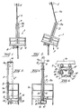
- Figure 1 illustrates the attitude taken by the cradle 1 when its centre of gravity acts in the direction of the line 4.
- the present invention overcomes this drawback, by enabling the distance "H" ( Figure 3) between the platform 2 and the attachment 6 at the upper free part 3a of the post 3 to be reduced when the upper free part 3a of said post is in co-action with the first attachment 5, when normal measures are taken to raise the cradle further. This is effected by causing the machine 8 to raise the platform 2 further.
- the post has the form of a rod or tube of uniform thickness.
- the post may have any desired cross-sectional shape, although the illustrated post has the outer cross-sectional shape shown in Figure 5.
- the post 3 is journalled in two journal devices or journals 11 and 12, of which one device 11 is rigidly attached to the uppermost part of the handrail or like guard 1a and he other device is mounted on the lowermost part of the guard.
- the post 3 has on its lowermost part a small projection 36 which will prevent the post from being moved axially upwards to an extent greater than that illustrated in Figure 3.
- the post 3 can still be moved downwards, however.
- Each of the spring devices consists of a tension spring of known configuration.
- the journals 11 and 12 are mutally identical, and it will be seen from Figure 4 that the device 11 is attached to the guard or handrail 1a of 11a.
- the line 4 is a double-line comprising line runs 4a, 4b each of which co-acts with a respective line pulley 15, 16.
- a single line as used in the present specification does not necessarily mean a line which consists of a single run, but also a line arrangement in which two or more line runs are arranged closely adjacent to one another.
- the cross-sectional shape of the post 3 is illustrated in Figure 5.
- the post of this embodiment is essentially of rectangular cross-section and consists of an extended aluminium profile.
- This profile has two mutually opposing runner surfaces 17, 18 and the distance between the runners is only insignificantly greater than the diameter of a ball bearing 19 mounted on a U-shaped rail 20 in a known manner.
- the rail 20 is attached to the guard or handrail in a known manner.
- the profile also has a further runner surface 21 against which the peripheral surface of a ball bearing (not shown) located beneath the ball bearing 19 will run.
- the profile also presents runner surfaces 17′, 18′ for a ball bearing 19′ and a further runner surface 21′ for co-action with the peripheral surface for a further ball bearing (not shown).
- the journal device identified generally by 11 in Figure 5 is identical with the journal 12.
- This arrangement of four bearings in the journal device 11 and four bearings in the journal device 12 will enable the post 3 attached to the cradle to be held torsionally rigid while still permitting the post to move up and down in the direction of its long axis.
- the post 3 is arranged externally of a guard 1a forming part of the cradle basket, whereas the guide 6 is located on the extremity of a horizontal projection 10 which extends in over the guard and terminates at a point which corresponds or substantially corresponds to the location of the centre of gravity of the cradle when unloaded.
- the cradle platform 2 may also have arranged on outer surfaces thereof, on either side of the line 4, support wheels which are intended to lie against the surface of the structure to be worked on with the aid of the cradle. This surface is indicated in Figure 3 and is referenced 16, and one wheel 17 is also shown in this Figure.
Landscapes
- Engineering & Computer Science (AREA)
- Architecture (AREA)
- Mechanical Engineering (AREA)
- Civil Engineering (AREA)
- Structural Engineering (AREA)
- Jib Cranes (AREA)
- Load-Engaging Elements For Cranes (AREA)
Priority Applications (1)
| Application Number | Priority Date | Filing Date | Title |
|---|---|---|---|
| AT89850089T ATE92567T1 (de) | 1988-03-17 | 1989-03-16 | Vorrichtung fuer haengebuehne. |
Applications Claiming Priority (4)
| Application Number | Priority Date | Filing Date | Title |
|---|---|---|---|
| SE8800976 | 1988-03-17 | ||
| SE8800976A SE464983B (sv) | 1988-03-17 | 1988-03-17 | Anordning vid haengstaellning |
| SE8804217 | 1988-11-22 | ||
| SE8804217A SE467164B (sv) | 1988-11-22 | 1988-11-22 | Anordning vid haengstaellning |
Publications (3)
| Publication Number | Publication Date |
|---|---|
| EP0333690A2 true EP0333690A2 (de) | 1989-09-20 |
| EP0333690A3 EP0333690A3 (en) | 1990-05-16 |
| EP0333690B1 EP0333690B1 (de) | 1993-08-04 |
Family
ID=26660139
Family Applications (1)
| Application Number | Title | Priority Date | Filing Date |
|---|---|---|---|
| EP89850089A Expired - Lifetime EP0333690B1 (de) | 1988-03-17 | 1989-03-16 | Vorrichtung für Hängebühne |
Country Status (3)
| Country | Link |
|---|---|
| US (1) | US4987971A (de) |
| EP (1) | EP0333690B1 (de) |
| DE (1) | DE68907962D1 (de) |
Cited By (2)
| Publication number | Priority date | Publication date | Assignee | Title |
|---|---|---|---|---|
| GB2294921A (en) * | 1994-11-09 | 1996-05-15 | E M & I | An Access Platform |
| GB2387833A (en) * | 2002-04-15 | 2003-10-29 | E M & I | A mobile access system and method of access thereof |
Families Citing this family (1)
| Publication number | Priority date | Publication date | Assignee | Title |
|---|---|---|---|---|
| US11247886B2 (en) * | 2018-01-11 | 2022-02-15 | Fritel & Associates, L.L.C. | Personnel basket for overhead cranes |
Family Cites Families (11)
| Publication number | Priority date | Publication date | Assignee | Title |
|---|---|---|---|---|
| US2662734A (en) * | 1952-06-13 | 1953-12-15 | Wilberd F Feigenbaum | Swing stage scaffold |
| FR1174851A (fr) * | 1957-05-09 | 1959-03-17 | Siège sellette ascenseur pour travaux sur parois verticales | |
| FR1236286A (fr) * | 1958-09-18 | 1960-07-15 | Spider Staging Inc | Treuil |
| US2998094A (en) * | 1958-09-18 | 1961-08-29 | Spider Staging Inc | Level winding winch mechanism |
| US3464520A (en) * | 1967-11-14 | 1969-09-02 | Leonard A Anderson | Self-operated elevator |
| US3630315A (en) * | 1970-09-08 | 1971-12-28 | Robert A Meyer | Seat scaffold |
| CA975405A (en) * | 1973-03-30 | 1975-09-30 | Arthur J. Leduc | Hoist basket |
| US3967696A (en) * | 1974-07-08 | 1976-07-06 | Donald James Nix | Stage safety stabilizer |
| US4225012A (en) * | 1979-04-06 | 1980-09-30 | International Telephone And Telegraph Corporation | Safety clamp device and apparatus utilizing same |
| US4650036A (en) * | 1985-05-09 | 1987-03-17 | Masako Matsuda | Emergency evacuation apparatus |
| US4602698A (en) * | 1985-05-13 | 1986-07-29 | Grant Walter R | Hunting chair |
-
1989
- 1989-03-16 EP EP89850089A patent/EP0333690B1/de not_active Expired - Lifetime
- 1989-03-16 DE DE8989850089T patent/DE68907962D1/de not_active Expired - Lifetime
- 1989-03-17 US US07/324,655 patent/US4987971A/en not_active Expired - Fee Related
Cited By (4)
| Publication number | Priority date | Publication date | Assignee | Title |
|---|---|---|---|---|
| GB2294921A (en) * | 1994-11-09 | 1996-05-15 | E M & I | An Access Platform |
| GB2294921B (en) * | 1994-11-09 | 1998-10-14 | E M & I | An access platform |
| GB2387833A (en) * | 2002-04-15 | 2003-10-29 | E M & I | A mobile access system and method of access thereof |
| GB2387833B (en) * | 2002-04-15 | 2005-04-13 | E M & I | A mobile access system and method |
Also Published As
| Publication number | Publication date |
|---|---|
| DE68907962D1 (de) | 1993-09-09 |
| EP0333690B1 (de) | 1993-08-04 |
| EP0333690A3 (en) | 1990-05-16 |
| US4987971A (en) | 1991-01-29 |
Similar Documents
| Publication | Publication Date | Title |
|---|---|---|
| US5033584A (en) | All-purpose ladder | |
| JP2017125363A (ja) | 風力発電装置におけるブレードのメンテナンス用ゴンドラ装置 | |
| CA1328630C (en) | Ergonomic aerial basket | |
| JP2011246894A (ja) | 作業用足場装置 | |
| EP0333690A2 (de) | Vorrichtung für Hängebühne | |
| CN210127623U (zh) | 一种建筑工程施工用的拉升吊篮 | |
| EP1700973A1 (de) | Tragarm für Leiter | |
| KR102554166B1 (ko) | 코너용 곤돌라 | |
| US2577286A (en) | Adjustable ladder jack and scaffold | |
| JP4707466B2 (ja) | 作業台着脱式昇降台及び作業台 | |
| CN212568200U (zh) | 一种公共建筑栏杆水平承载力检测设备 | |
| JPH0737319B2 (ja) | ゴンドラ懸吊装置 | |
| CN221242748U (zh) | 一种清洁设备的移动机构 | |
| JP2805588B2 (ja) | 作業用ゴンドラ | |
| CN221256090U (zh) | 一种具有抗倾覆结构的造楼设备支撑装置 | |
| CN213477601U (zh) | 装配式建筑可移动外挂施工平台 | |
| CN115215252B (zh) | 升降装置和起重机 | |
| JP3124057U (ja) | ユニックアーム吊設用足場 | |
| KR200213318Y1 (ko) | 엘리베이터 승강홀 작업대 | |
| KR102890013B1 (ko) | 와이어를 이용한 안전 리프트 | |
| CN215326574U (zh) | 吊装组件 | |
| JP3857282B2 (ja) | 荷受台昇降装置における荷受台の最上昇位置決め装置 | |
| CN222795022U (zh) | 一种设备吊装结构 | |
| CN216511224U (zh) | 一种物料支撑装置 | |
| CN220377764U (zh) | 一种具有防掉落功能的脚手架 |
Legal Events
| Date | Code | Title | Description |
|---|---|---|---|
| PUAI | Public reference made under article 153(3) epc to a published international application that has entered the european phase |
Free format text: ORIGINAL CODE: 0009012 |
|
| AK | Designated contracting states |
Kind code of ref document: A2 Designated state(s): AT BE CH DE ES FR GB GR IT LI LU NL SE |
|
| PUAL | Search report despatched |
Free format text: ORIGINAL CODE: 0009013 |
|
| AK | Designated contracting states |
Kind code of ref document: A3 Designated state(s): AT BE CH DE ES FR GB GR IT LI LU NL SE |
|
| 17P | Request for examination filed |
Effective date: 19900914 |
|
| 17Q | First examination report despatched |
Effective date: 19910508 |
|
| GRAA | (expected) grant |
Free format text: ORIGINAL CODE: 0009210 |
|
| AK | Designated contracting states |
Kind code of ref document: B1 Designated state(s): AT BE CH DE ES FR GB GR IT LI LU NL SE |
|
| PG25 | Lapsed in a contracting state [announced via postgrant information from national office to epo] |
Ref country code: IT Free format text: LAPSE BECAUSE OF FAILURE TO SUBMIT A TRANSLATION OF THE DESCRIPTION OR TO PAY THE FEE WITHIN THE PRESCRIBED TIME-LIMIT;WARNING: LAPSES OF ITALIAN PATENTS WITH EFFECTIVE DATE BEFORE 2007 MAY HAVE OCCURRED AT ANY TIME BEFORE 2007. THE CORRECT EFFECTIVE DATE MAY BE DIFFERENT FROM THE ONE RECORDED. Effective date: 19930804 Ref country code: CH Effective date: 19930804 Ref country code: GR Free format text: LAPSE BECAUSE OF FAILURE TO SUBMIT A TRANSLATION OF THE DESCRIPTION OR TO PAY THE FEE WITHIN THE PRESCRIBED TIME-LIMIT Effective date: 19930804 Ref country code: NL Effective date: 19930804 Ref country code: SE Effective date: 19930804 Ref country code: AT Effective date: 19930804 Ref country code: FR Effective date: 19930804 Ref country code: ES Free format text: THE PATENT HAS BEEN ANNULLED BY A DECISION OF A NATIONAL AUTHORITY Effective date: 19930804 Ref country code: LI Effective date: 19930804 Ref country code: BE Effective date: 19930804 Ref country code: DE Effective date: 19930804 |
|
| REF | Corresponds to: |
Ref document number: 92567 Country of ref document: AT Date of ref document: 19930815 Kind code of ref document: T |
|
| REF | Corresponds to: |
Ref document number: 68907962 Country of ref document: DE Date of ref document: 19930909 |
|
| REG | Reference to a national code |
Ref country code: CH Ref legal event code: PL |
|
| EN | Fr: translation not filed | ||
| NLV1 | Nl: lapsed or annulled due to failure to fulfill the requirements of art. 29p and 29m of the patents act | ||
| PG25 | Lapsed in a contracting state [announced via postgrant information from national office to epo] |
Ref country code: GB Effective date: 19940316 |
|
| PG25 | Lapsed in a contracting state [announced via postgrant information from national office to epo] |
Ref country code: LU Free format text: LAPSE BECAUSE OF NON-PAYMENT OF DUE FEES Effective date: 19940331 |
|
| PLBE | No opposition filed within time limit |
Free format text: ORIGINAL CODE: 0009261 |
|
| STAA | Information on the status of an ep patent application or granted ep patent |
Free format text: STATUS: NO OPPOSITION FILED WITHIN TIME LIMIT |
|
| 26N | No opposition filed | ||
| GBPC | Gb: european patent ceased through non-payment of renewal fee |
Effective date: 19940316 |